- JT Mechanical
- 2012 JK Mechanical
- JK Mechanical
- 2007 Torques
- 5 Tire Rotation
- Diagnostic Codes
- Drain Plugs
- Cowl Removal
- Fender Flare Removal
- Fuses
- Gear Ratio Charts
- Hardtop Seal Replacement
- Headlight Adjustment
- Headlight Blub Replacement
- Instrument Test
- Labels, Lamps, Etc.
- Lubrication and Fluids
- Reprogramming Keyless Entry
- Parking Brake Adjustment
- Rollbar Pad Removalt
- Seatbelt Chime Disable
- Sentry Key Programming
- Steering Alignment
- Steering Stops
- Washer Tank Cap
- TJ/LJ Mechanical
- Oil Change
- Repairs / Rebuilds
- 3.6L Oil Cooler Replacement
- 3.6L Oxygen Sensor Replacement
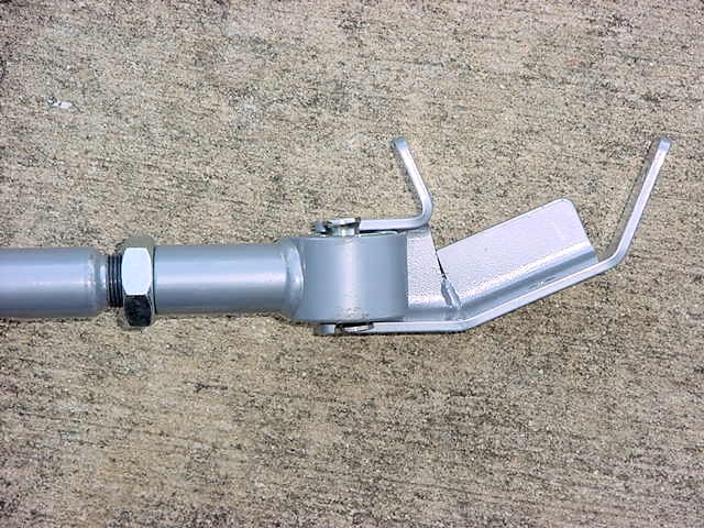
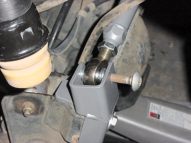
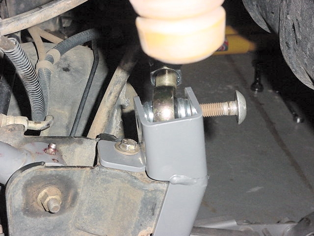
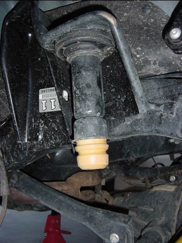
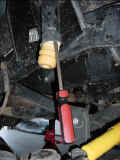
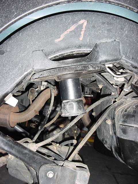
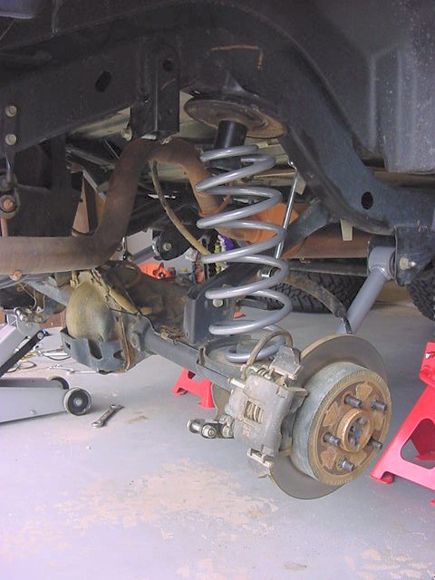
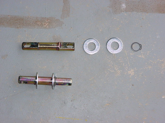
- Johnny Joint Rebuild
- Hi-Lift Jack
- Front Brake Lines
- JK Rear Brake Pads
- JK Steering Shaft
- Norgren Pressure Regulator
- P0128 (Coolant) Trouble Code
- Softtop Front Air Leak Repair
- Softtop Bow Repair
- Sunvisor Repair
- Warn xd9000i Winch
- Winch Controller Rewire
- ZJ Fuel Pump
- Shop Tools
- Miscellaneous
- Armor
- Crane Differential COver
- Entry Guards
- Kilby Gas tank Skid
- Kilby Steering Skid
- Light Guards
- Limb Risers
- Medic Engine Skid
- Medic Long Arm Engine Skid
- Medic Tummy Tuck
- OYR Rear Corners
- Rokmen Rear Corners
- Rokmen Sliders
- Rubicon Express Rear Bumper
- SafariGard Rear Bumper
- Stepshield
- TBT Front Light Bar
- TBT Stinger Front Bumper
- TBT TJ Gas Tank Skid
- TBT LJ Gas Tank Skid
- TBT Sport Cage
- Tomken "Protec" Bumpers
- Warn Differential Skids
- Lifts / Suspension
- Brake Light Relocation
- Goferit Motor Mount Lift
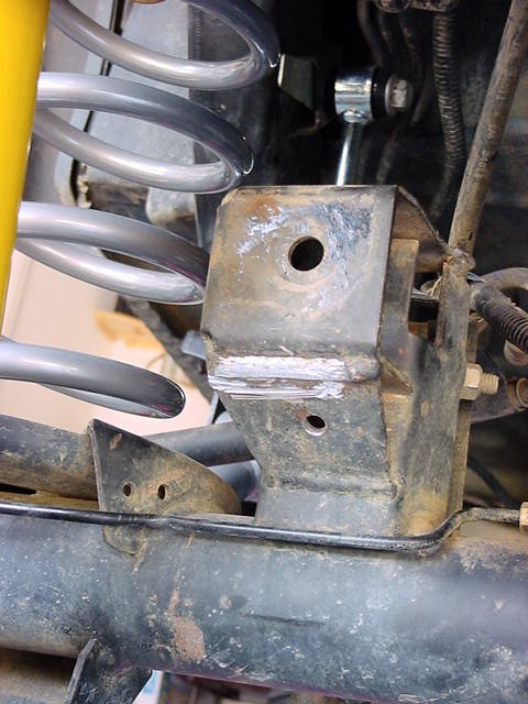
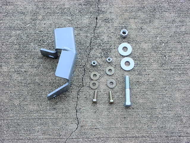
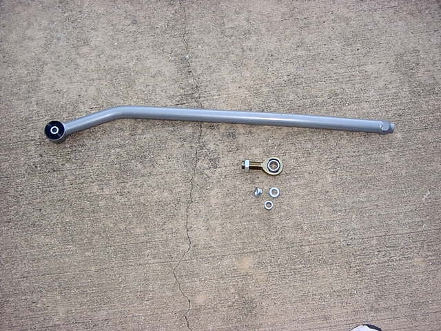
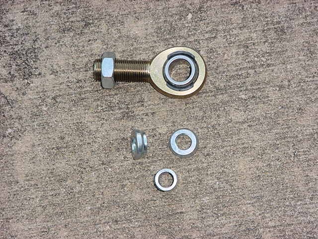
- JKS Adj. Track Bar
- JKS Body Lift
- JKS Budget Motor Mount Lift
- JKS Quicker Disconnects
- Monroe Steering Stabilizer
- MORE Motor Mount Lift
- OME Steering Stabilizer
- OME Suspension Lift
- ORO AiROCK
- ORO SwayLOC
- ORO U-Turn
- Ron's Sway Bar Clips
- Rubicon Express Long Arm Suspension
- Rubicon Express Superflex Kit
- Skyjacker Shifter Bracket
- Sway Bar Collars
- Teraflex Shock Relocators
- Tri-County Gear Body Lift
- Tri-County Gear Track Bar Brace
- Tri-County Gear Motor Mount Lift
- Electrical / Electronics
- Engine
- OnBoard Air
- Recovery
- Security
- Wheels
- Miscellaneous
- Anker Power Drive 5
- Bartact Fire Extinguisher Holder
- Bestop Trail Cover
- Bow Ends
- Bug Deflector
- Daystar D-Ring Isolators
- Dual Tire Inflation System
- Fender Flares
- Folding Shovel
- Gavan FRED emergency light
- Hood Bumpers
- Inclinometer
- Jeep Grill Wall Art
- Kidde Fire Extinguisher
- Locking Gas Cap
- Kilby's Welder Plate
- Mag-Lite Flashlight
- Quick Fist Roll Bar Mount
- RAM Mounts
- RR Cable Stop
- Seat Belt Keepers
- Sport Handles
- Water Mist Cooling
- Wet Okole Seat Covers
- Armor
- Crawler Conceptz Body Mounted Tire Carrier
- Crawler Conceptz Hi-Lift Jack Holder
- EVO Evap Skid
- EVO Protek Skids
- Gas Cover
- Jeep Entry Guards
- Kilby Evap Relocator
- River Raider Skid Plates
- Rockcrusher Differential Covers
- Rugged Ridge Taillight Guards
- StoneHenge Series Front Bumper
- StoneHenge Series Rear Bumper
- Terafelx Dana 44 Covers
- Trimming Pinch Seam and Rock Rails
- Lift / Suspension
- Adam's Front Driveshaft
- Axle Breather Extensions
- Clayton 4.5" Suspension Lift
- Crown Performance Brake Line
- Disconnect Motor Flip
- DIY Rear Spring Retainers
- Front Brake lines to the Rear
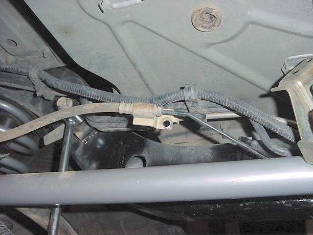
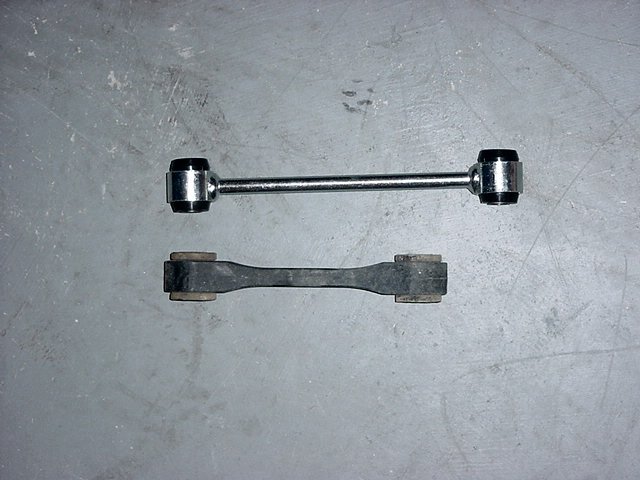
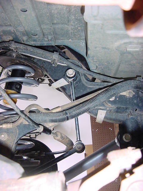
- Home Made Extended Swaybar Links
- Hubcentric Spacers
- ORO AiROCK
- JKS Front Adj. Trackbar
- JKS Geometry Correction Bracket
- JKS Spring Retainers
- Monroe Steering Stabilizer
- PolyPerformance Exhaust Spacer 2012+
- RE Extended Brake Lines
- RockKrawler Spring Wedge
- RockKrawler 2.5" Stock Mod
- Synergy Rear Anti-swaybar links
- Synergy Rear Track Bar Bracket
- Synergy Rear Adjustable Trackbar
- Teraflex 2.5" Budget Boost
- Teraflex Coil Spring Retainers
- Teraflex HD Ball Joints
- Teraflex Steering Stabilizer
- Woods Steering Stabilizer Relocator
- Electrical / Electronics
- 12vdc Outlets
- AntennaX
- Battery Terminals
- Bracketron
- CB Radio Installation
- Center Console LED Lights
- Dash Mounted USB Power
- Dual Battery Tray
- Genesis Dual Battery Tray
- Hood Light Brackets
- Interior LED Lights
- Kilby Power Panels
- LED Fog Light Bulbs
- Mic Holder
- 2012 Optima Battery
- Pilot PLX LED Cubes
- Poison Spyder A-Pillar mount
- Power Inverter
- SilverStar Headlights
- sPOD
- Tantrum Lighting System
- Teraflex CB Mount
- Engine
- OnBoard Air
- Recovery
- Security
- Wheels
- Miscellaneous
- 3rd brake light
- 12LED Flashlight
- Anker Power Drive 5
- ARB Recovery Bag
- Badlands Soft Shackle
- Baofeng UV-5G
- Bartact Fire Extinguisher Holder
- Bug Deflector
- 2012 Cabin Air Filter
- Husky Cargo Liner
- D-Rings
- Daystar D-Ring Isolators
- DIY Dash Bar
- DIY 4way Inflate/Deflate System
- Dual Tire Inflation System
- EVO Vacuum Pump Relocation
- Electronic Lighter
- Extra Reverse Lights
- Farm Jack Cover
- Folding Shovel
- Front Bumper Non-Slip
- Gavan FRED emergency light
- Gerber Strap Cutter
- Grill Inserts
- Grill Inserts(Clip in)
- Grill Screws
- Handle Inserts
- Hi-Lift Handle Keeper
- Hood Bumpers
- Hood Decal
- Jeep Grab Handles
- Jeep Grill Wall Art
- Jeep Hanger
- Jeep Knives
- Jeep Multi-Tool
- Locking Gas Cap
- Jeep Rubicon Radio/TV
- Jeep Steering Wheel Cover
- Jeep Sunshade
- JL Hood Latches
- Kidde Fire Extinguisher
- Midland MXT275
- MORE Dead Pedal
- OBDII Splitter and Reader
- Paracord Projects
- Quick Fist Mag Lite Mount
- Quick Fist Roll Bar Mount
- RAM Mounts
- RotopaX Mounts and Containers
- RR Cable Stop
- Seat Massagers
- Side View Mirror Drains
- Slush Mats
- SmittyBilt Winch Cable Pull
- Spare Tire Brake Light
- Tailgate Latch
- Tailgate Shock
- Trasharoo
- Trim Painting
- Vector Dash Bar Full Width
- Vector Exo-Rack
- Winch Cable Stop