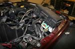
I have been looking for a dual battery tray for the Jeep Wrangler JK's to finally come out. Benchmark Design and M.O.R.E both released there's at about the same time, though Benchmark was the only one shipping. I was able to get a Benchmark one from a friend who couldn't put his in since he installed a supercharger. Thanks Bill.
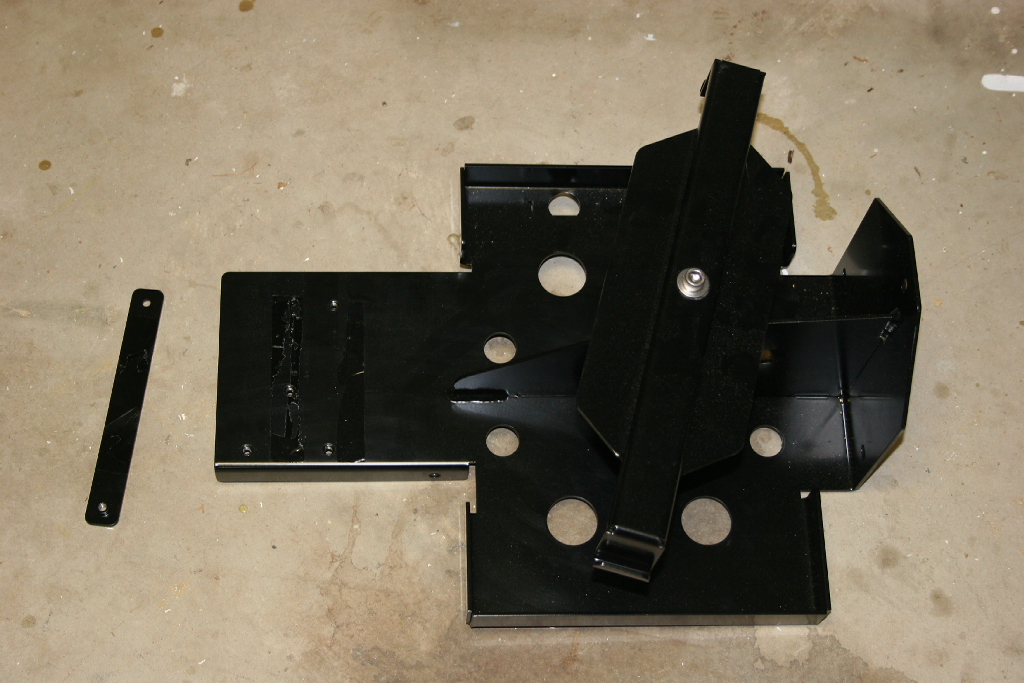
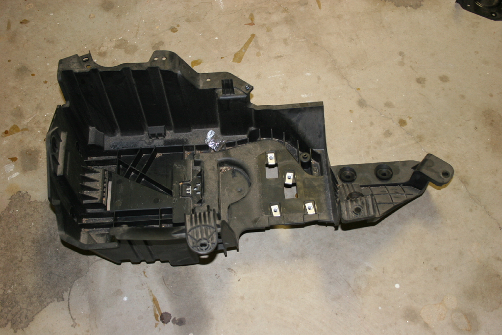
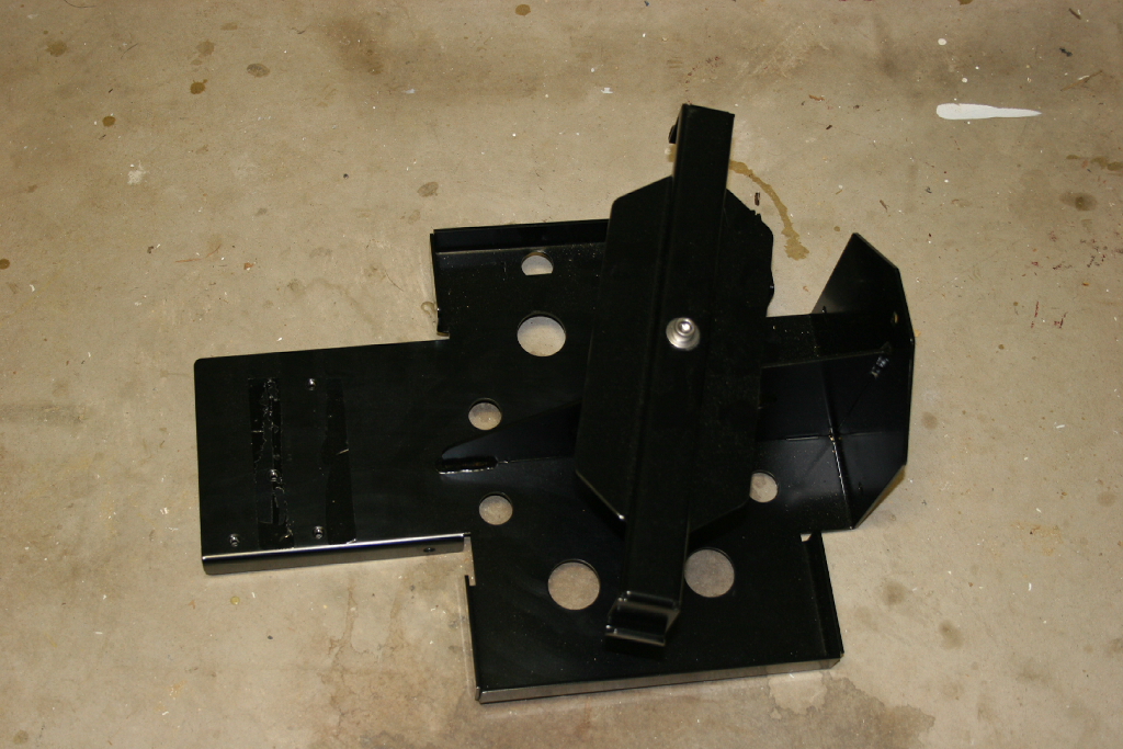
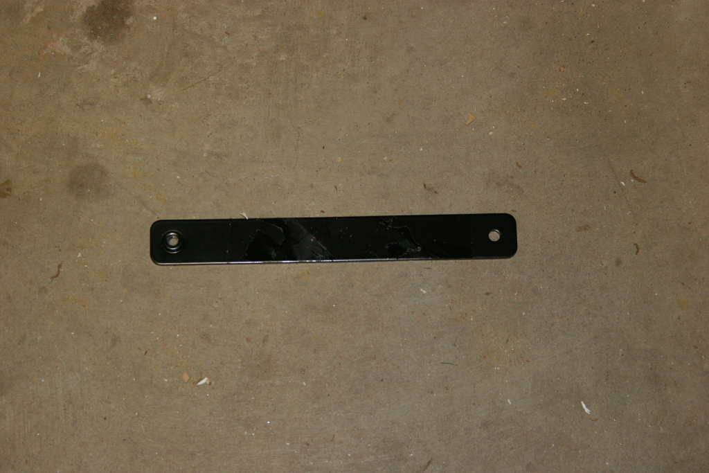
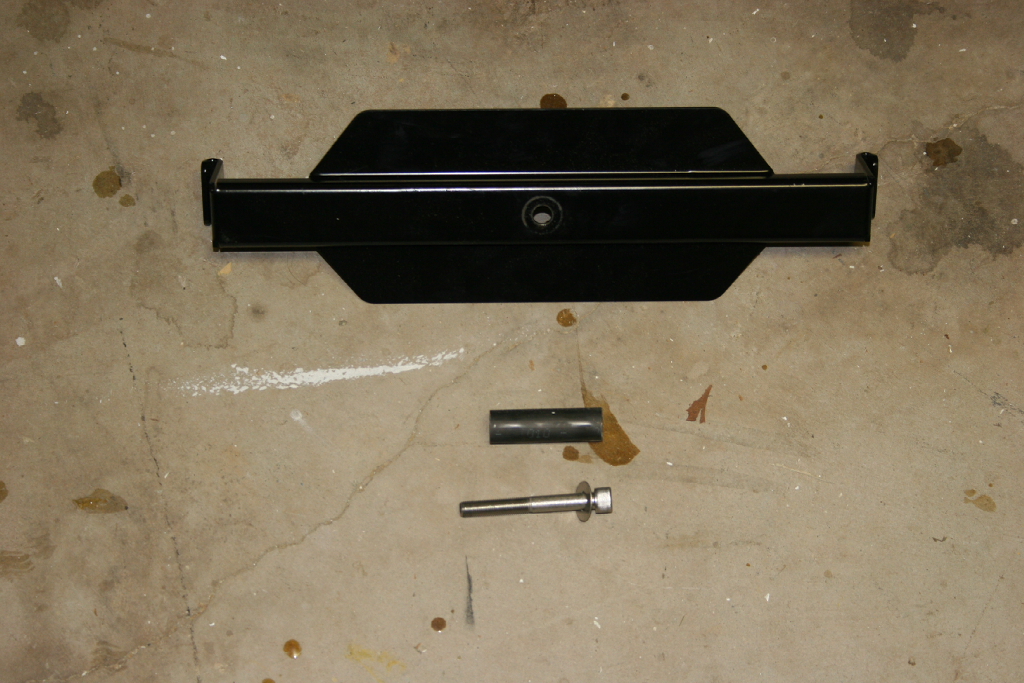
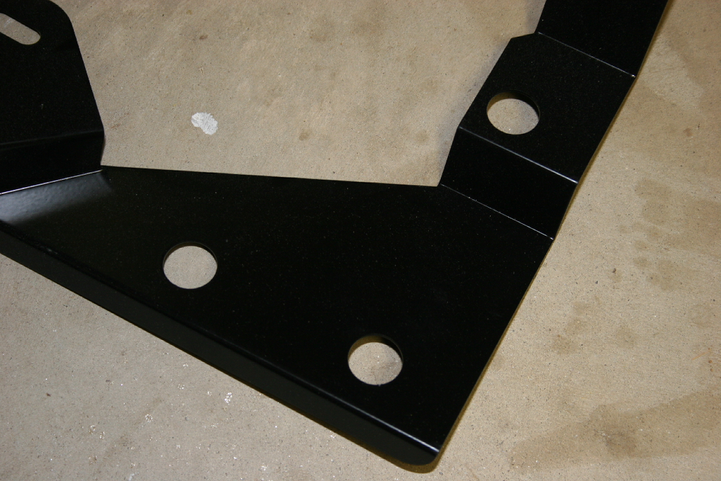
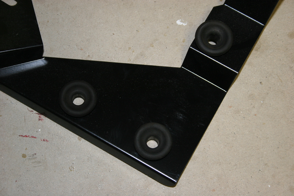
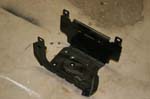
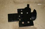
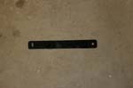
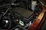
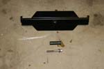
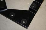
| The parts, not much. The tray, a brace, and the hold down bracket. I am still waiting for the bracket to hold the air filter box. |
 |
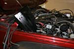
| I recommend parking on a flat surface and turning your front wheels to the left if you do not have a lift with aftermarket shocks installed with the rod end up. You may need to remove the left front shock to access a bolt hole that will be used in step 28 and 29. |
 |
| |
| Installation: |
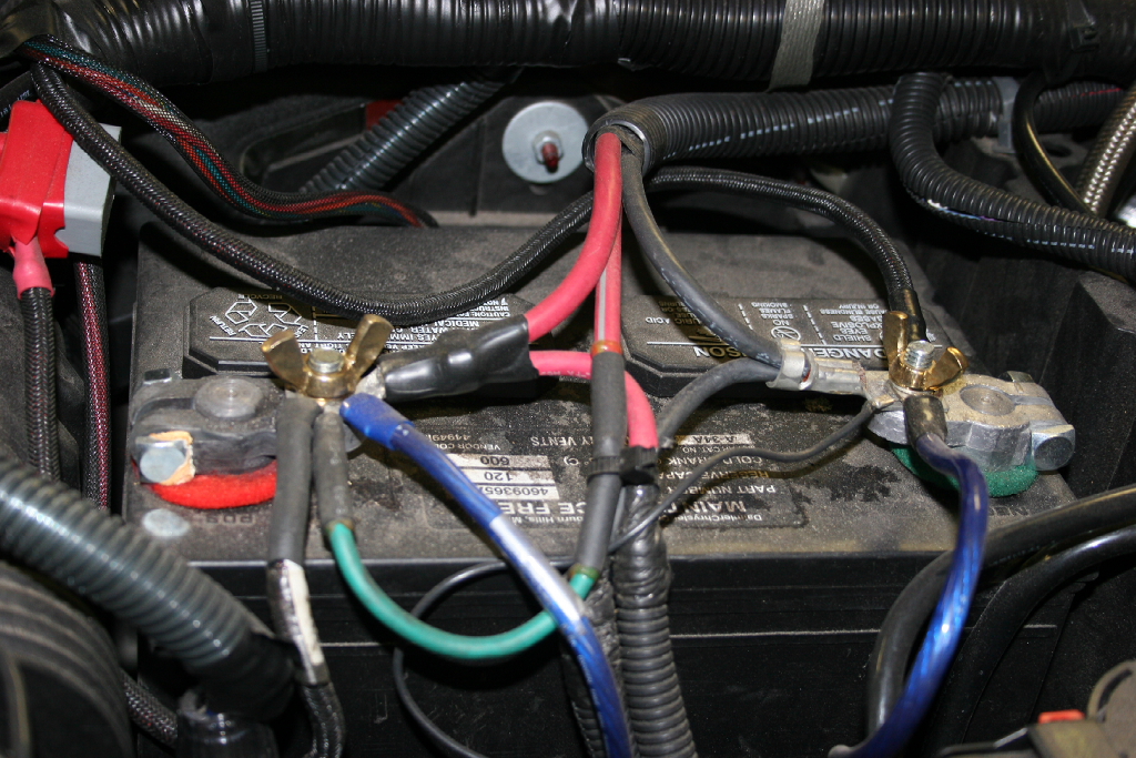
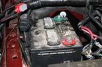
1. Disconnect the battery. A 10mm combo wrench for the stock battery clips, or whatever fits if you have modified them a little.
Note: You should wear gloves and goggles when working around the battery. |
 |
 |
 |
| 2. Remove the battery hold down clamp with a 10mm socket and a long extension. |
 |
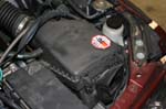
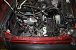
3. Remove the battery and put it somewhere safe.
Note: The battery is heavy, and in there very tight. Be careful pulling it out. You should wear gloves and goggles when working around the battery. |
 |
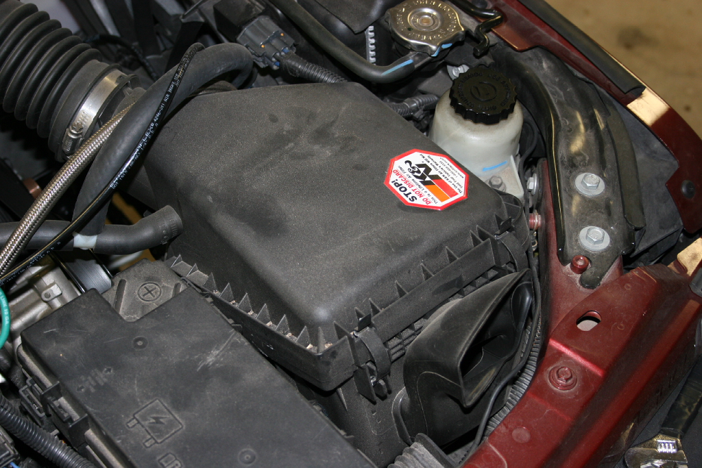
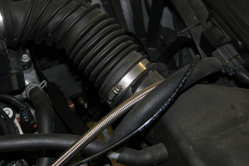
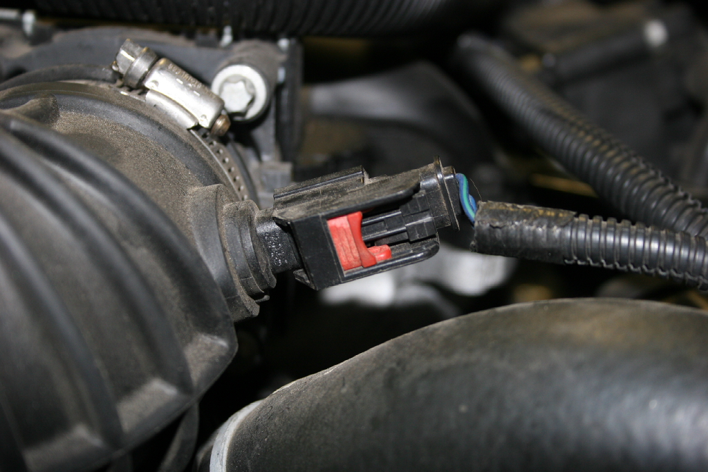
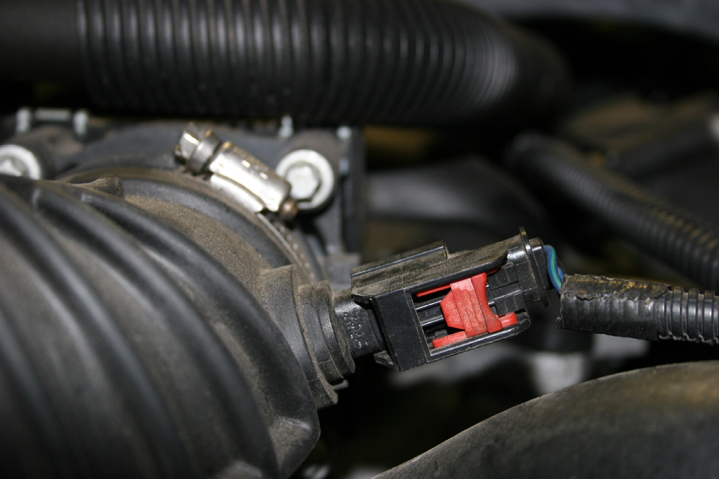
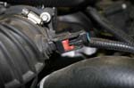
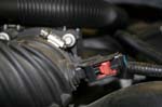
| 4. Use a flat tip screwdriver to loosen the clamp on the air tube connected to the air box. I found that removing the entire tube and reinstalling it later made things much easier. Pull up on the red lock tab for the IAT sensor, disconnect the connector from the IAT sensor. Loosen the clamp on the air tube to throttle body. Disconnect the air tube from the air box. |
 |
 |
 |
 |
 |
 |
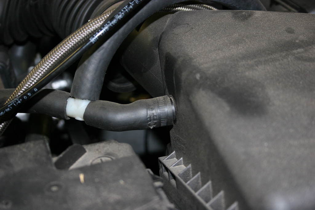
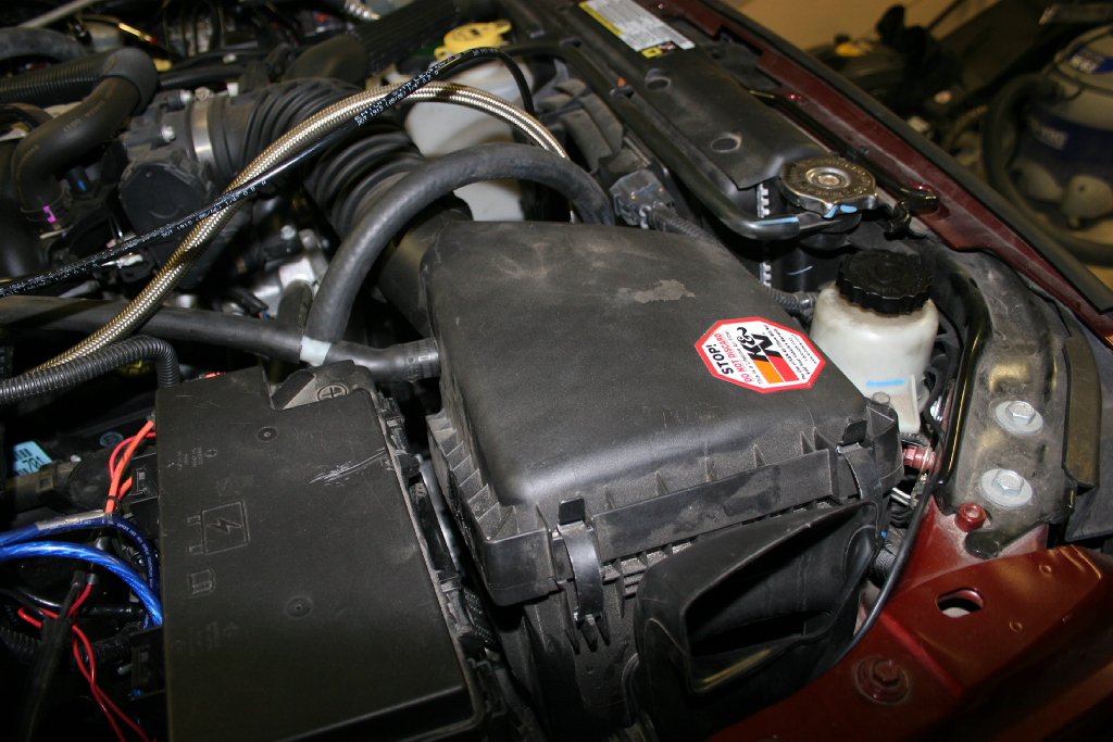
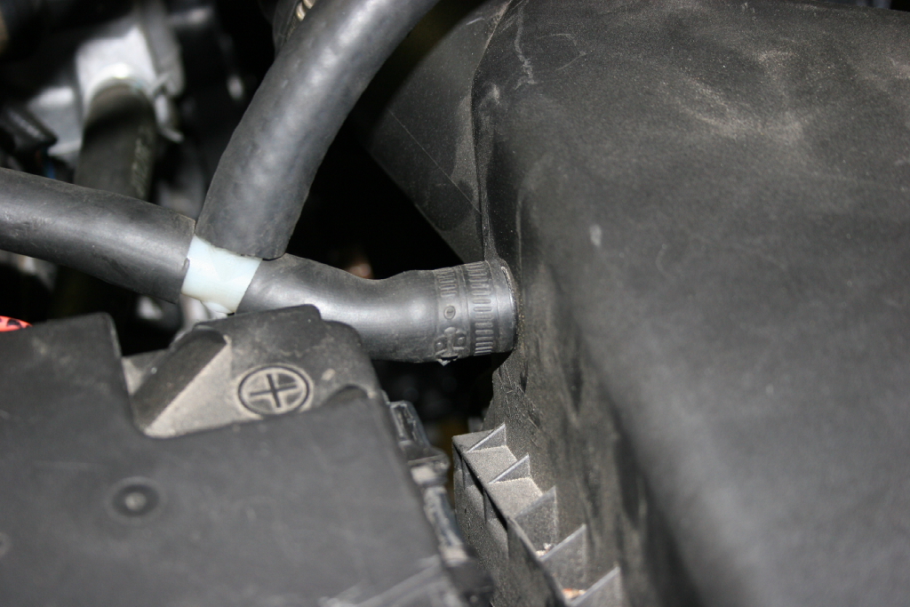
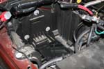
| 5. Remove the crankcase vent from the side of the air box. Is should just pull off, but you might have to give it a little twist back and forth to break the seal first. |
 |
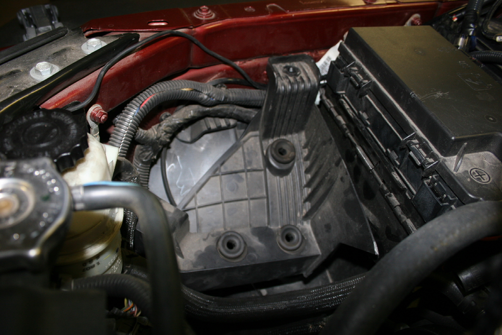
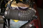
| 6. Pull the air box up and off. It is connected by 3 feet underneeth that fit into rubber grommets. If the grommets pull out of the tray, just remove them from the feet and reinstall them in the tray underneath. |
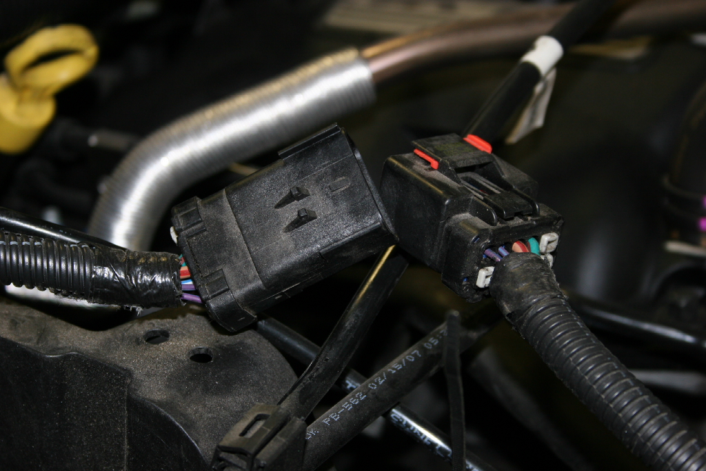
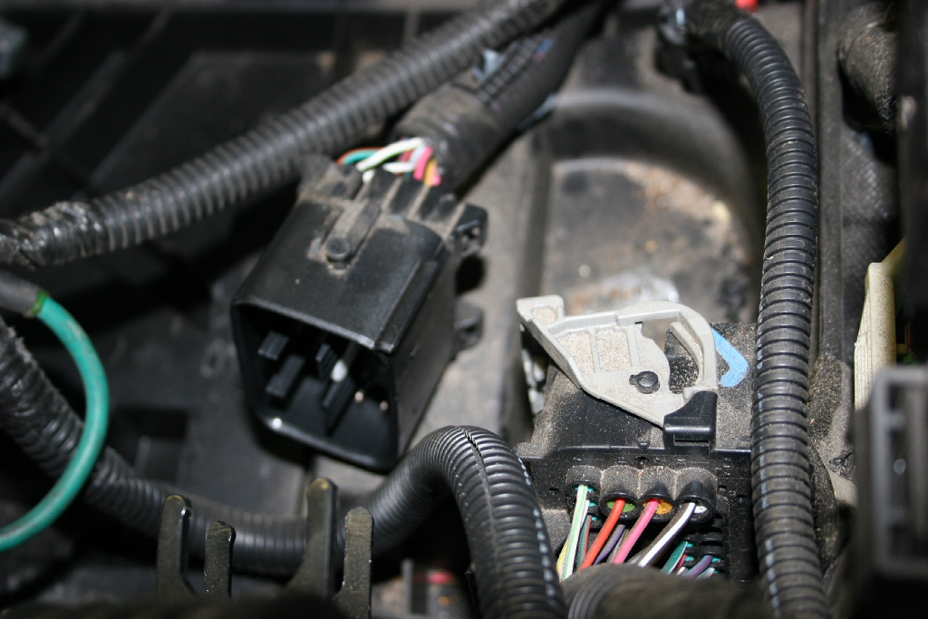
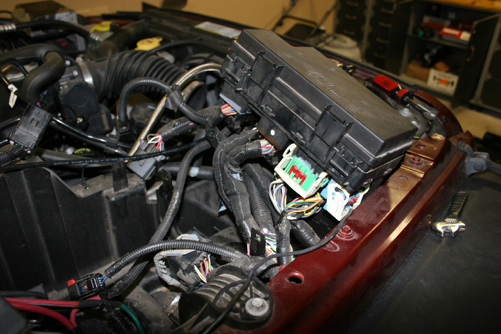
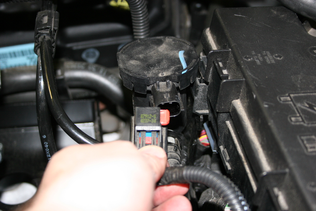
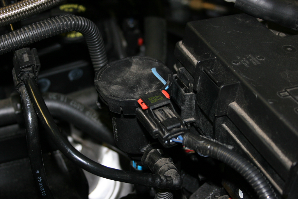
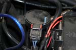
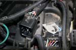
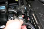
| 7. Disconnect the connector on top of the battery tray. Pull the red clip out and then press the release and pull apart. Detatch the connector from the battery tray. You should be able to gently pry it off with a flat tip screwdriver underneath. |
 |
 |
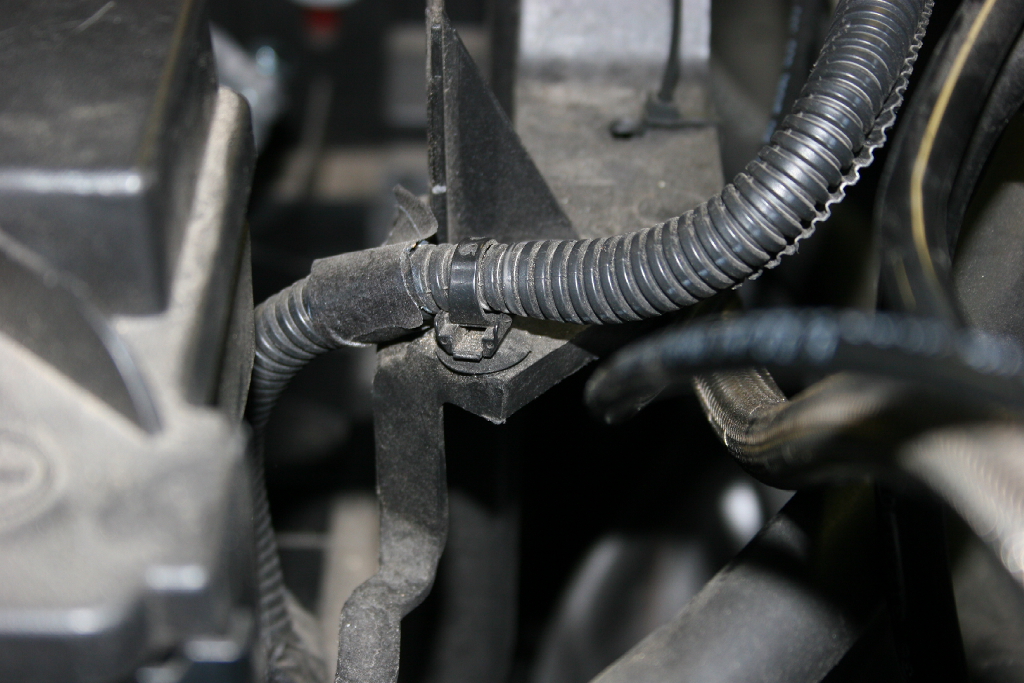
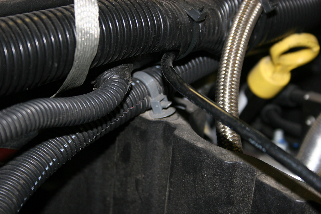
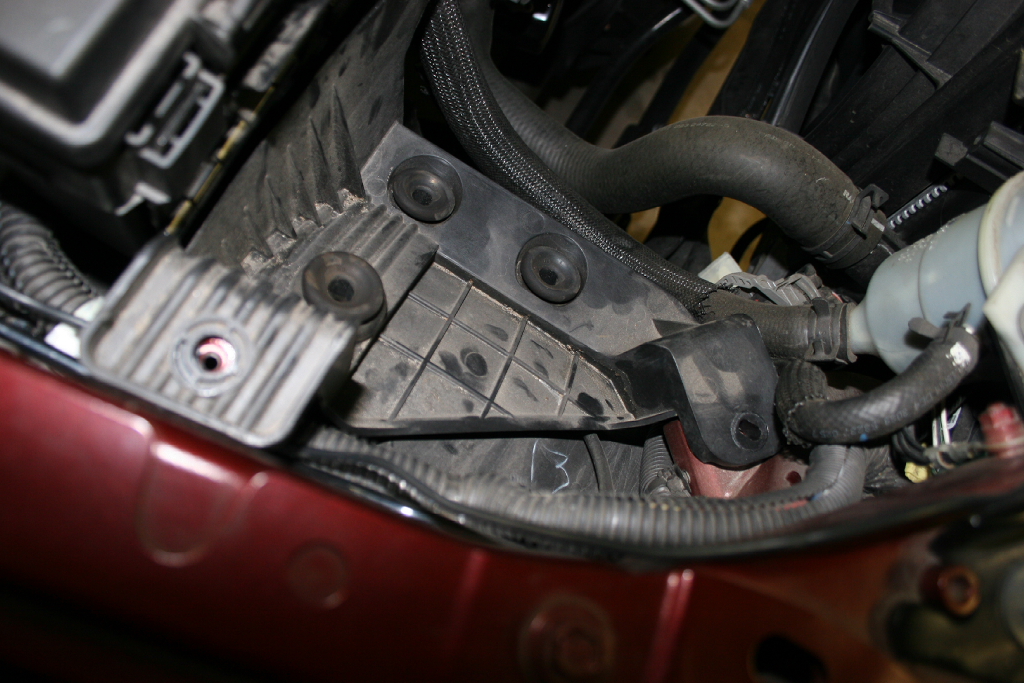
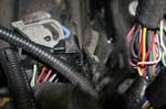
| 8. Now follow the wire bundle in both directions and remove the tie downs from the battery tray. There should be two of them. You may need a pliers to assist in getting these off. |
 |
 |
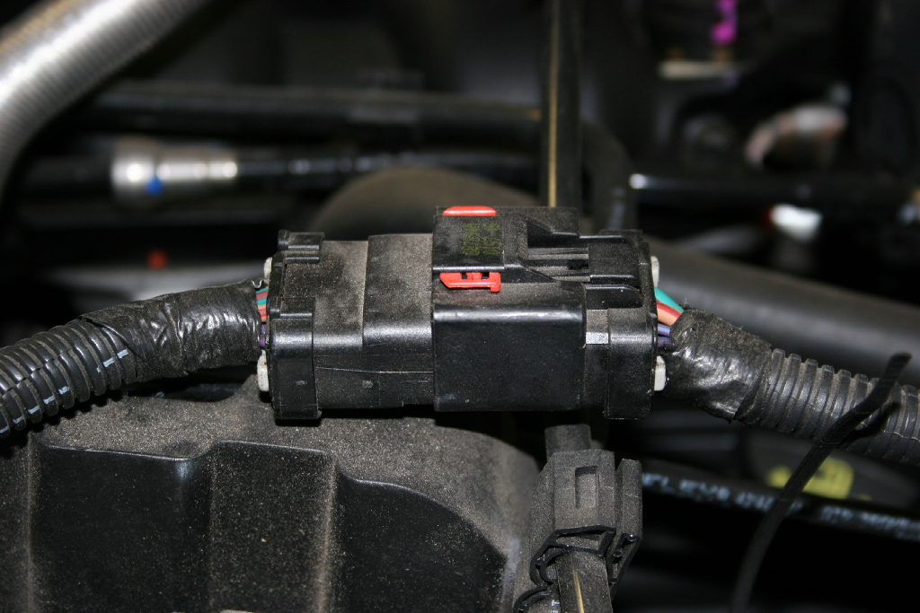
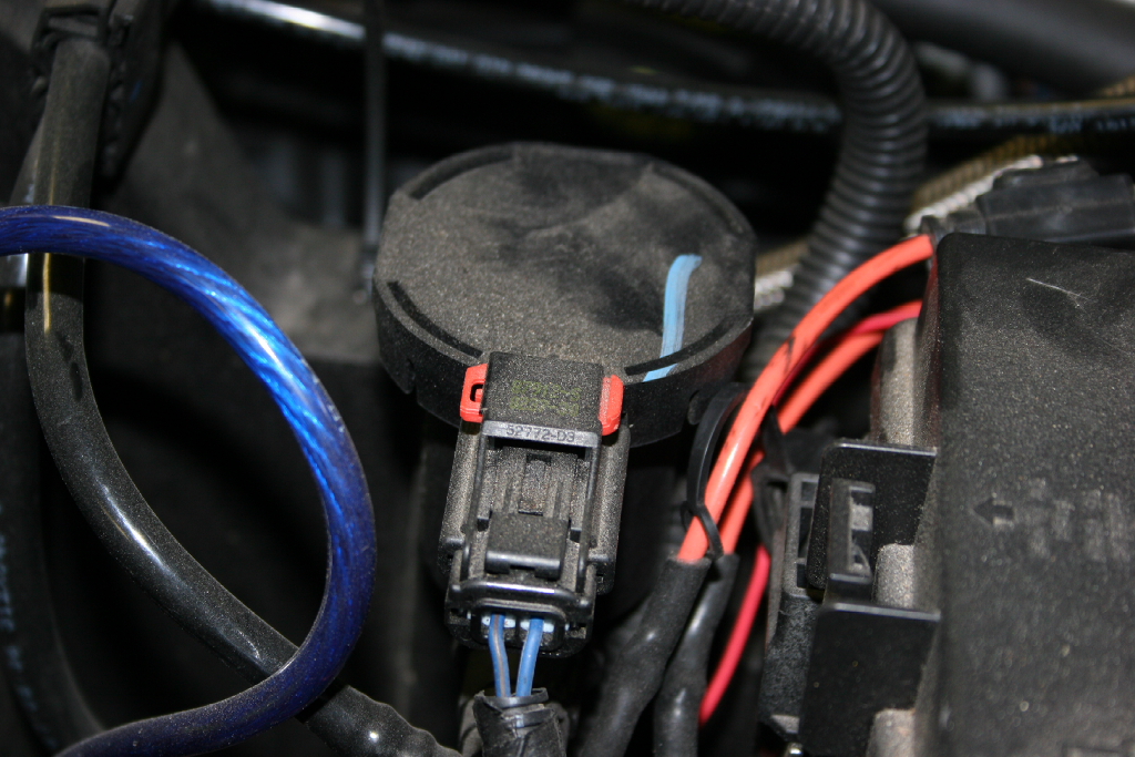
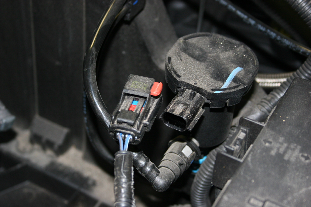
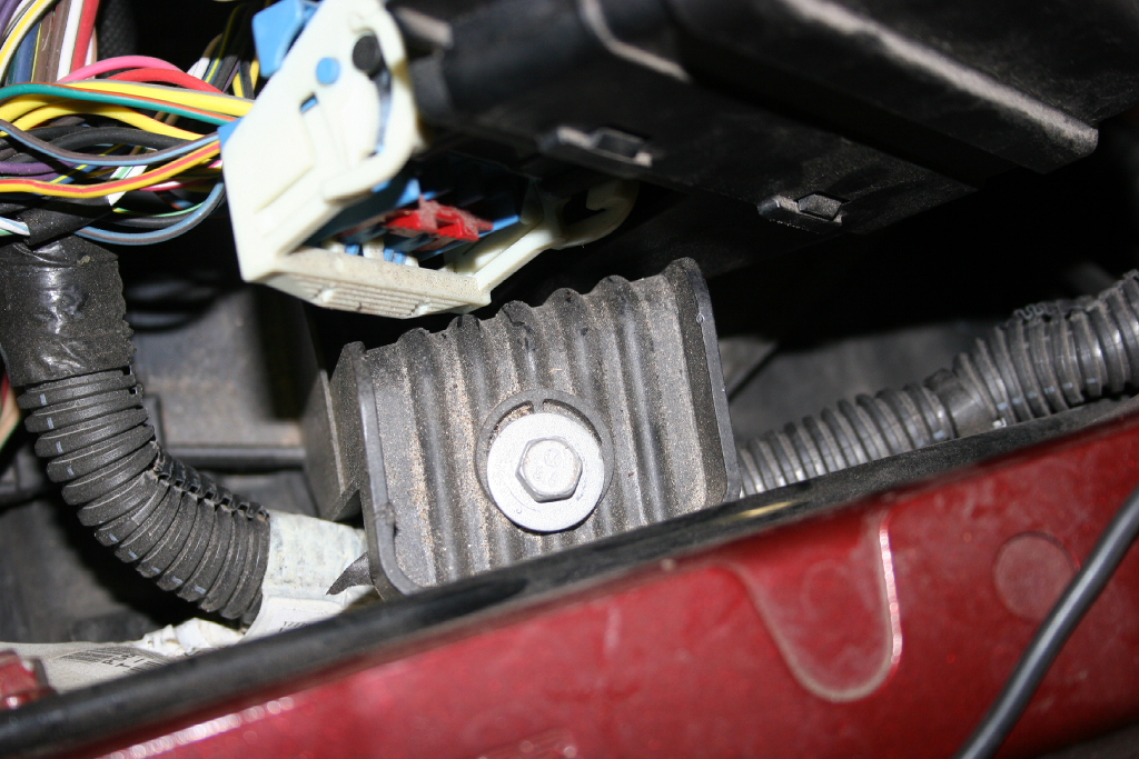
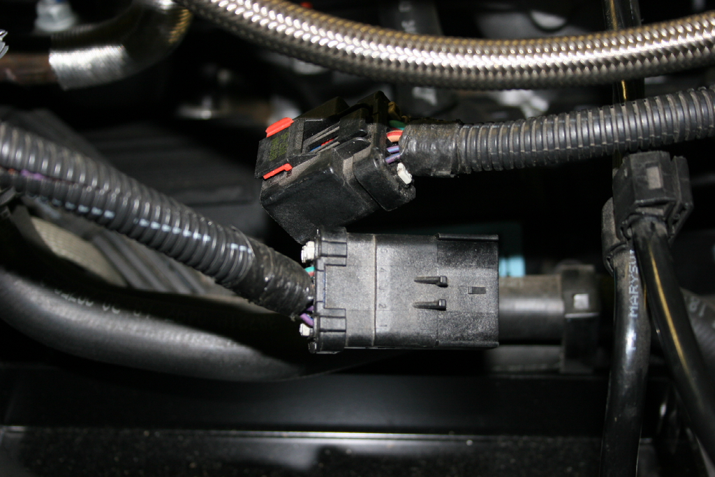
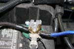
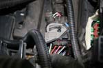
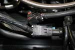
| 9. Disconnect the connector from the evaporative purge solenoid. Pull the red clip out to the side, press down on the release and pull apart. |
 |
 |
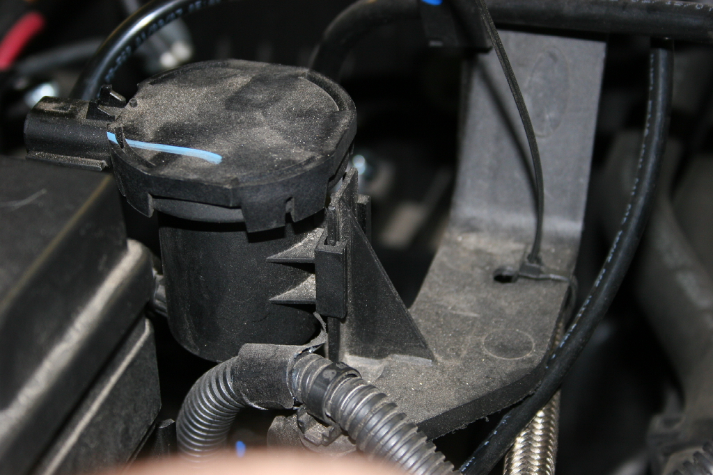
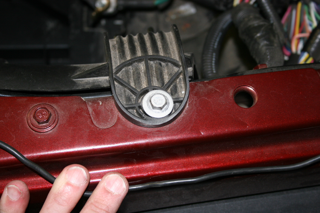
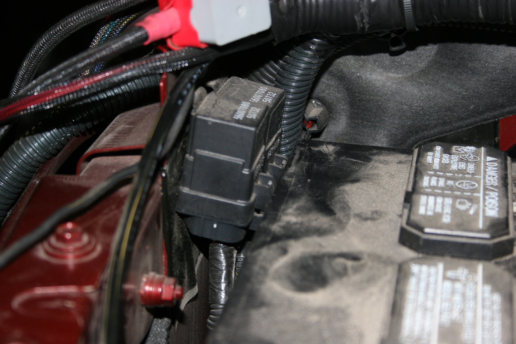
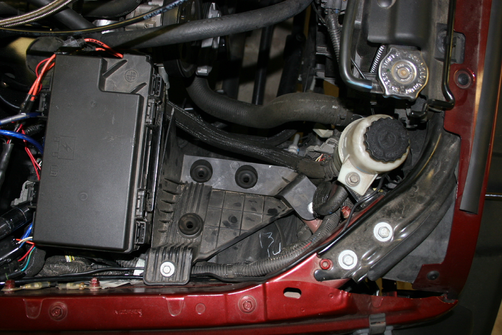
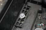
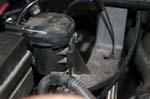
| 10. Lift the evaporative purge solenoid off of it's mount on the side of the battery tray. I moved it out of the way towards the engine. |
 |
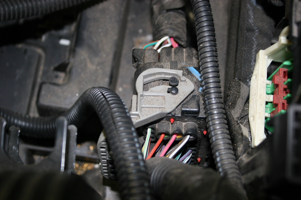
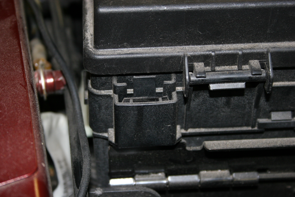
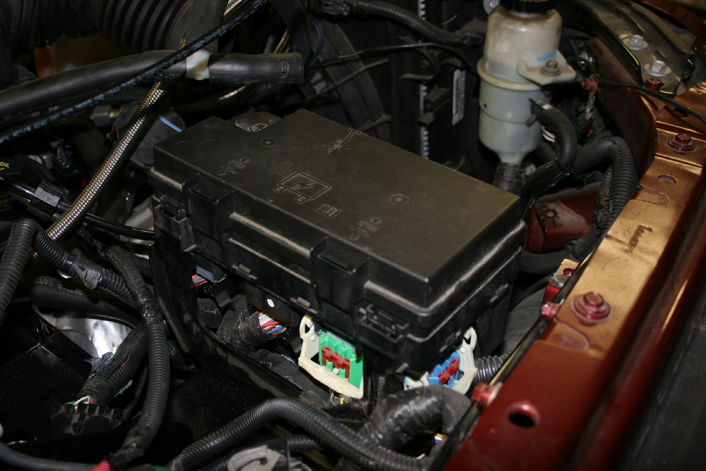
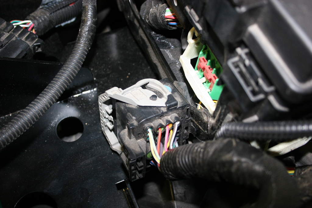
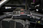
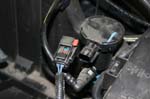
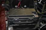
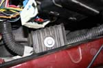
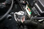
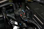
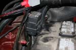
| 11. Disconnect the large electrical connector on the side of the TIPM (Fuse box). Press the release and rotate the lever all the way forward. This lever (Grey in the picture) locks 2 pins on the other part. You will see the slot that they pull out through when it is rotated far enough forward. |
 |
 |
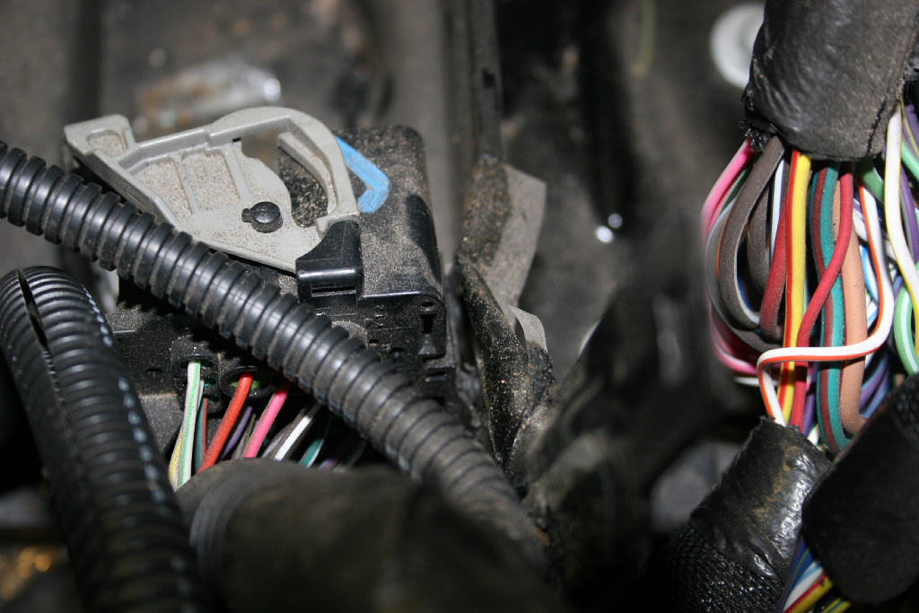
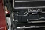
| 12. Remove the large electrical connector from the side of the TIPM (Fuse box). Gently pry it off the side with a flat tip screwdriver |
 |
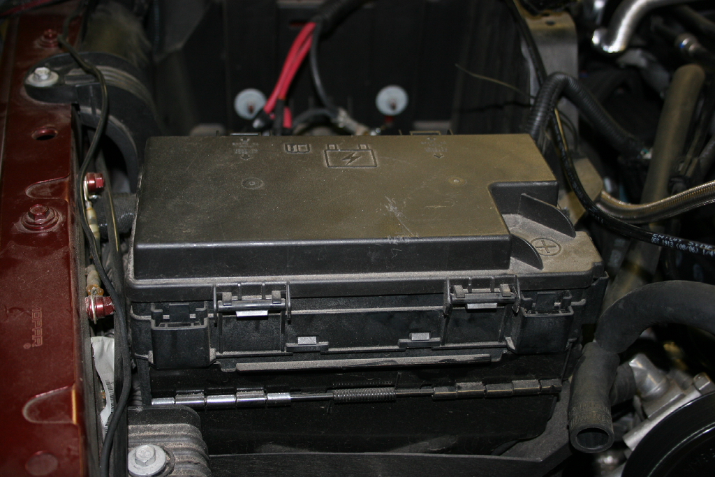
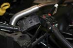
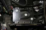
| 13. Remove the TIPM (Fuse Box) from the TIPM bracket. The TIPM is held in by four plastic clips, two on each side. Press the clips in while you work the box up. My TIPM bracket had a spring hinge on the front side (don't know if this has changed on the newer models), so doing the two clips on the battery side and then the two clips on the front side allowed it to come off the easiest. |
 |
 |
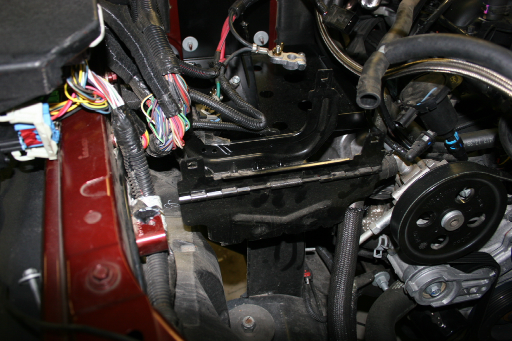
| 14. Lift the TIPM up and move it out of the way as best you can. |
 |
| 15. Remove the bolts holding the TIPM bracket to the battery tray with a 10mm socket, extension and ratchet. |
 |
 |
| 16. Remove the three nuts holding the battery tray to the firewall with a 10mm socket. Put these aside, they will be reused. |
 |
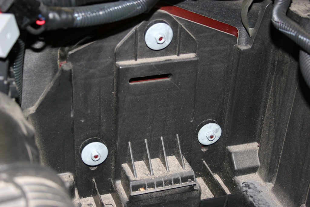
| 17. Remove the four bolts holding the battery tray to the fender with a 10mm socket and extension. |
 |
 |
 |
 |
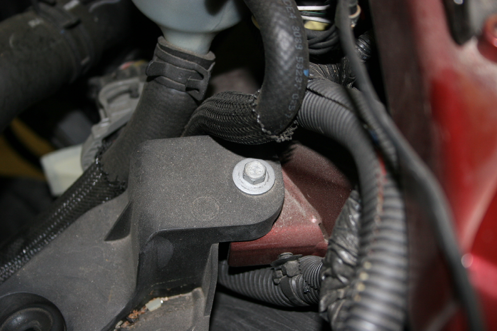
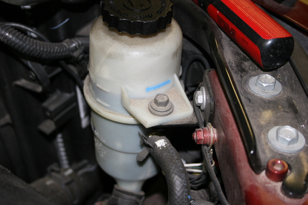
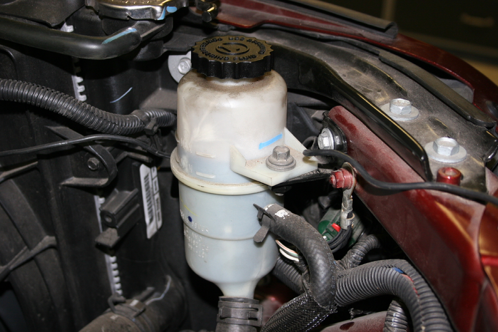
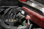
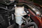
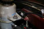
| 18. Remove the power steering reservoir and bracket from the radiator core support with a 10mm socket. It is much easier to get the battery tray out with the bracket removed from the core support, I tried it the other way and it doesn't work. |
 |
 |
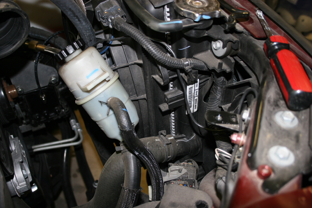
| 19. Position the power steering reservoir out of the way. |
 |
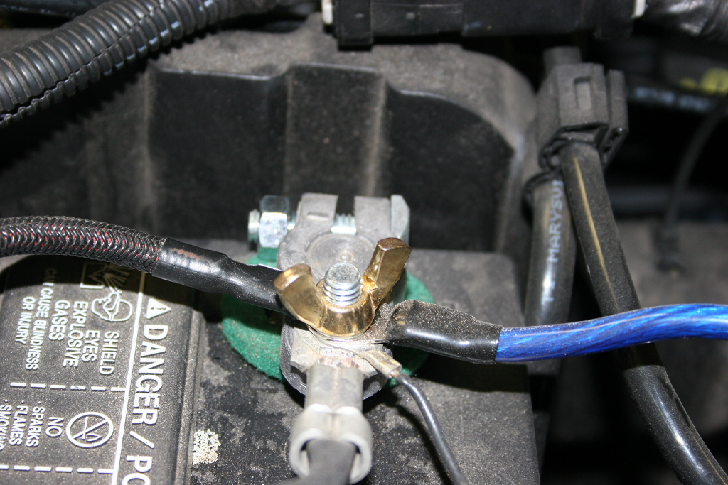
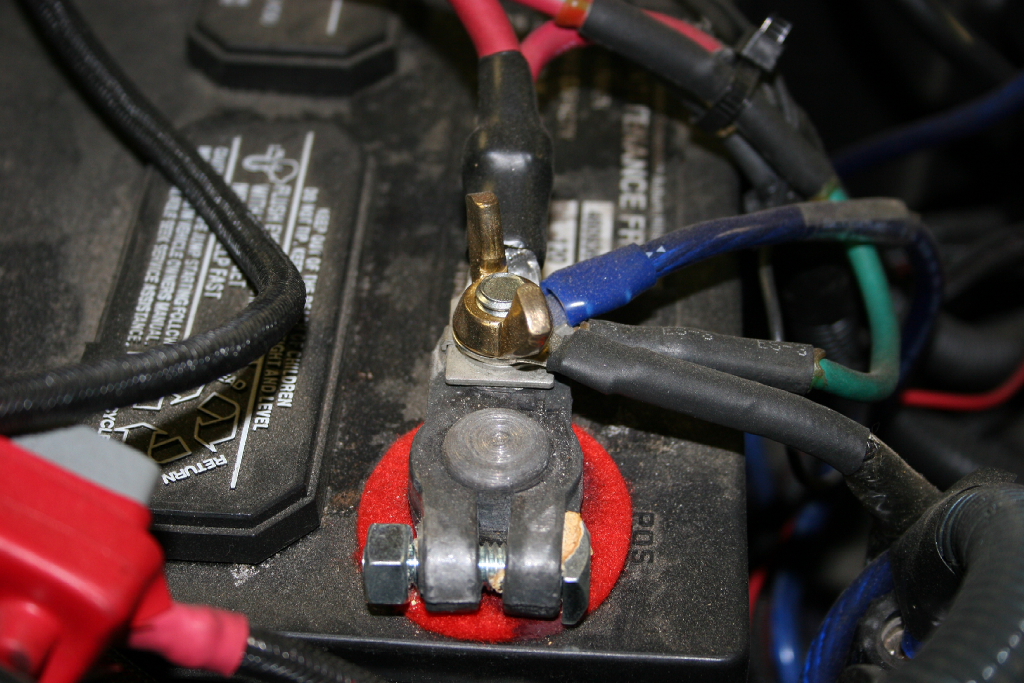
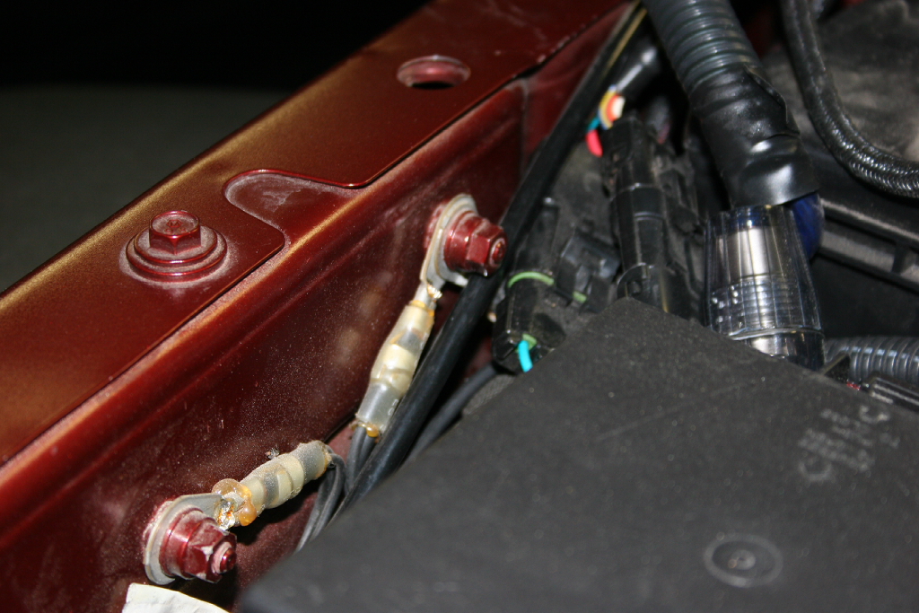
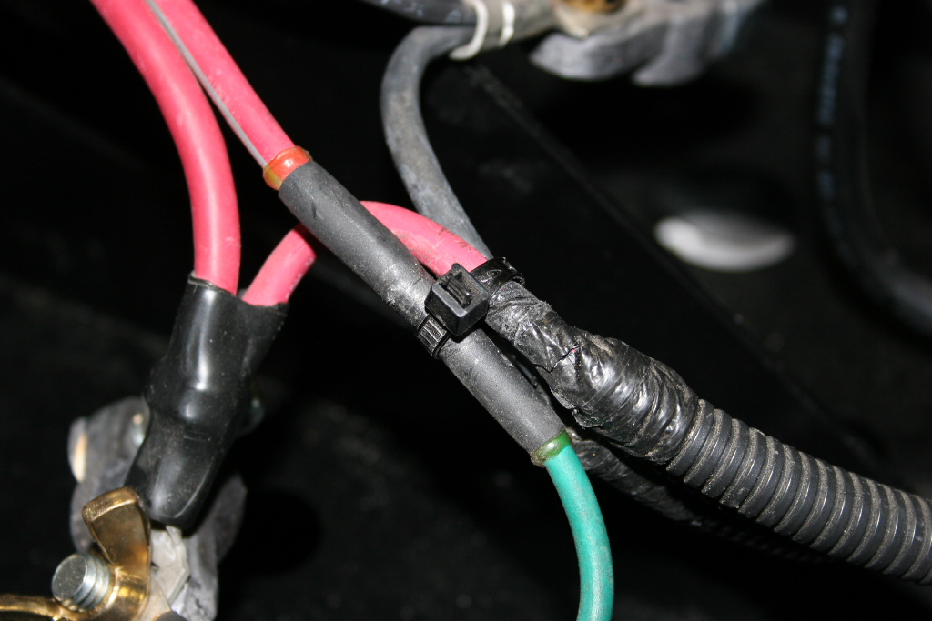
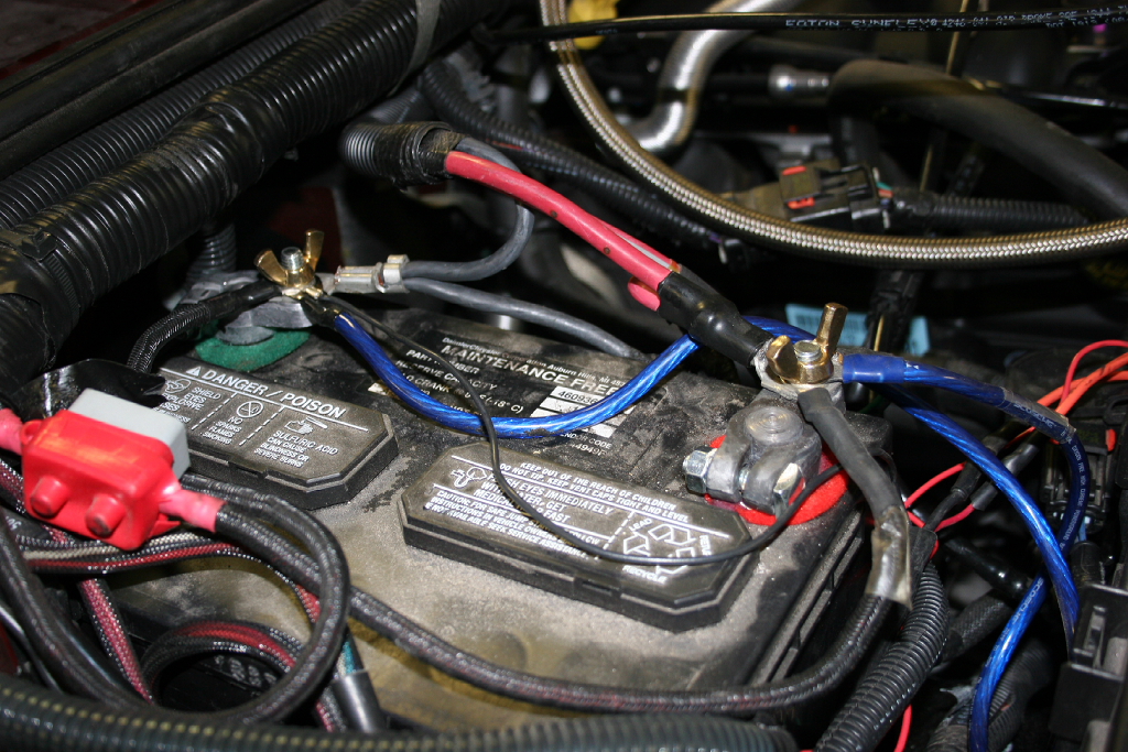
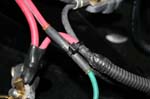
| 20. Use a 10mm wrench to disconnect main chassis ground cable that runs from the battery clamp to the stud on the inner fender. (Disconnect only the fender end of the cable. There is no need to disconnect the cable from the battery clamp.) |
 |
| 21. Push the battery cables out of the way towards the engine. |
|
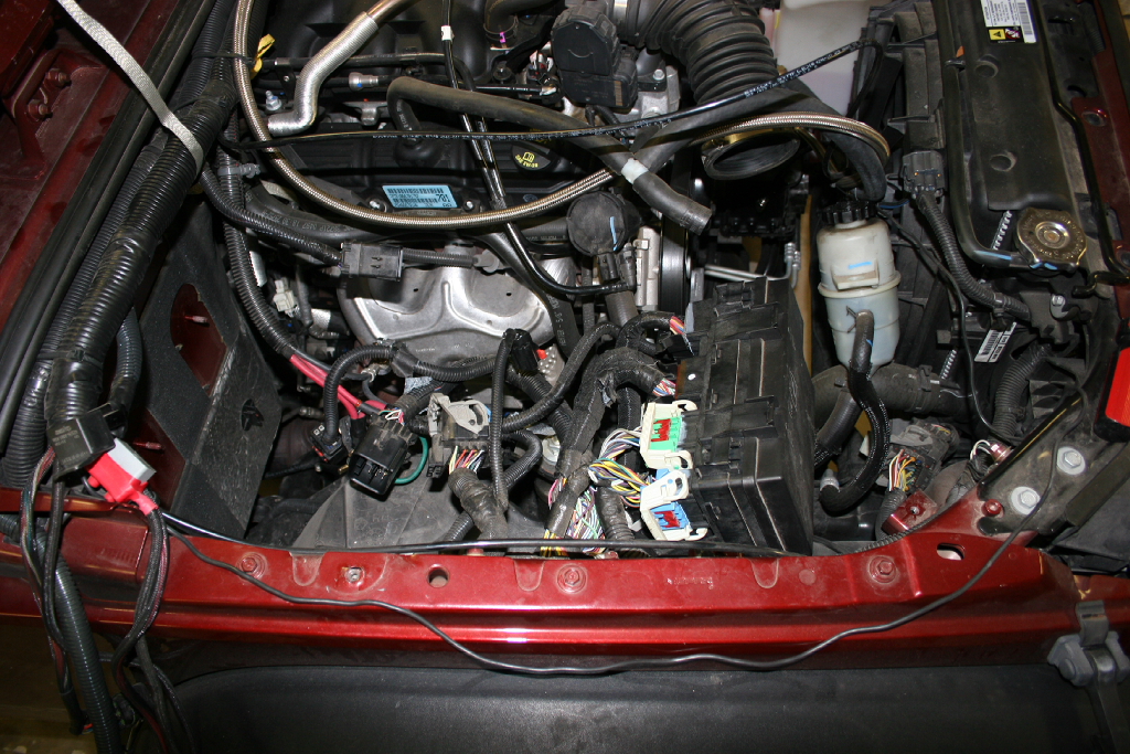
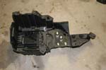
| 22. Lift up the front of the battery tray and pull the tray up and out of the vehicle. Just work all the cables and everything up and off as you pull the tray out. |
 |
 |
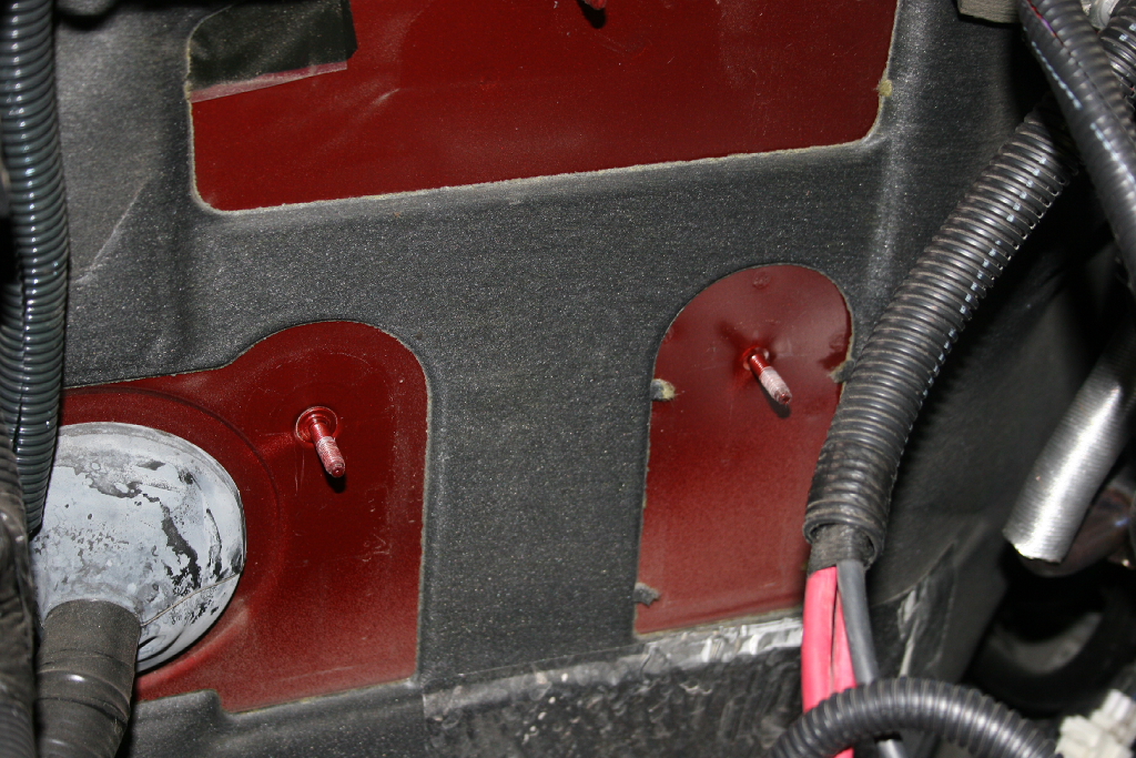
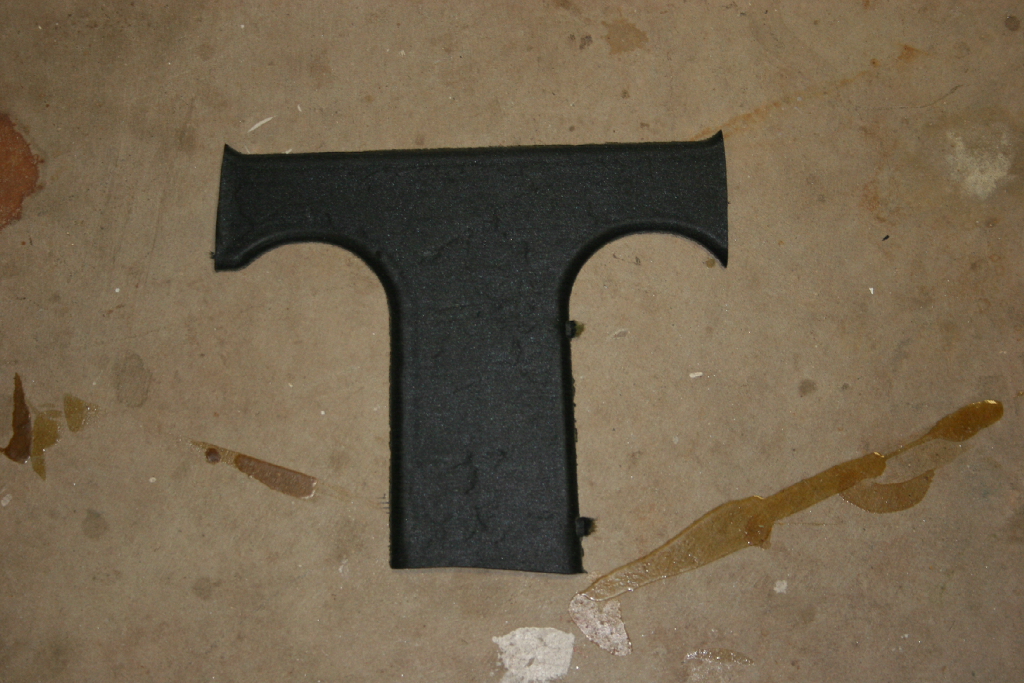
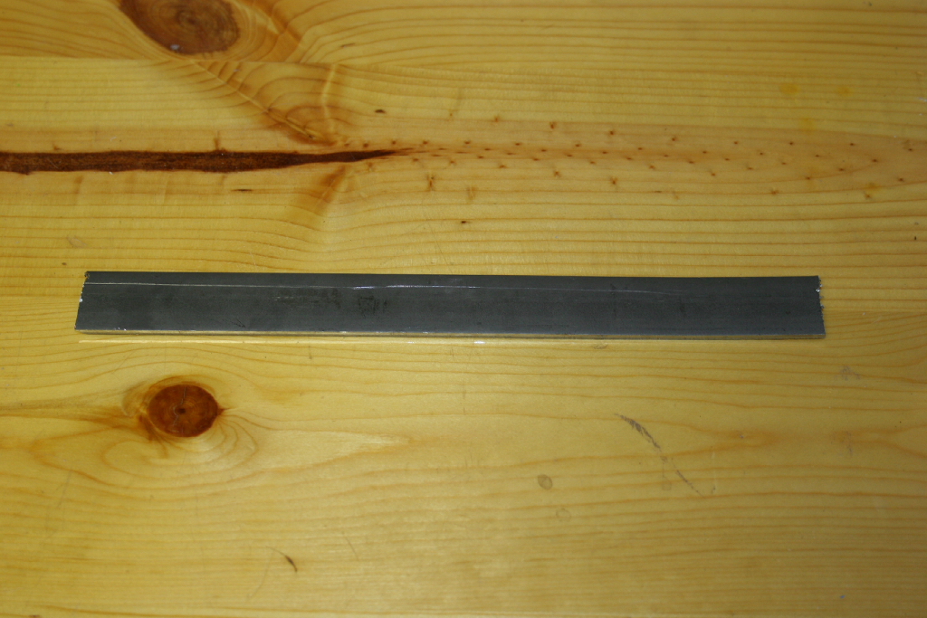
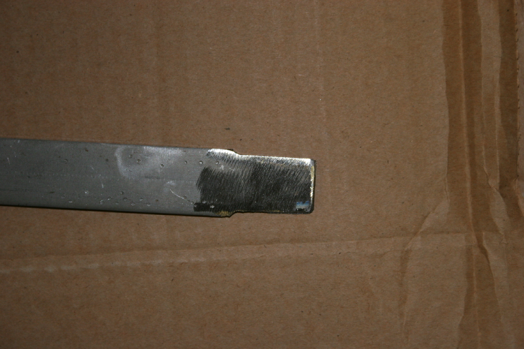
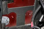
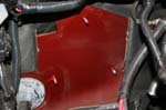
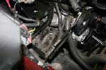
| 23. With a razor blade, cut the T shaped section of insulation off of the firewall where the new battery tray will mount. This allows for a good solid seat against the firewall. |
 |
 |
 |
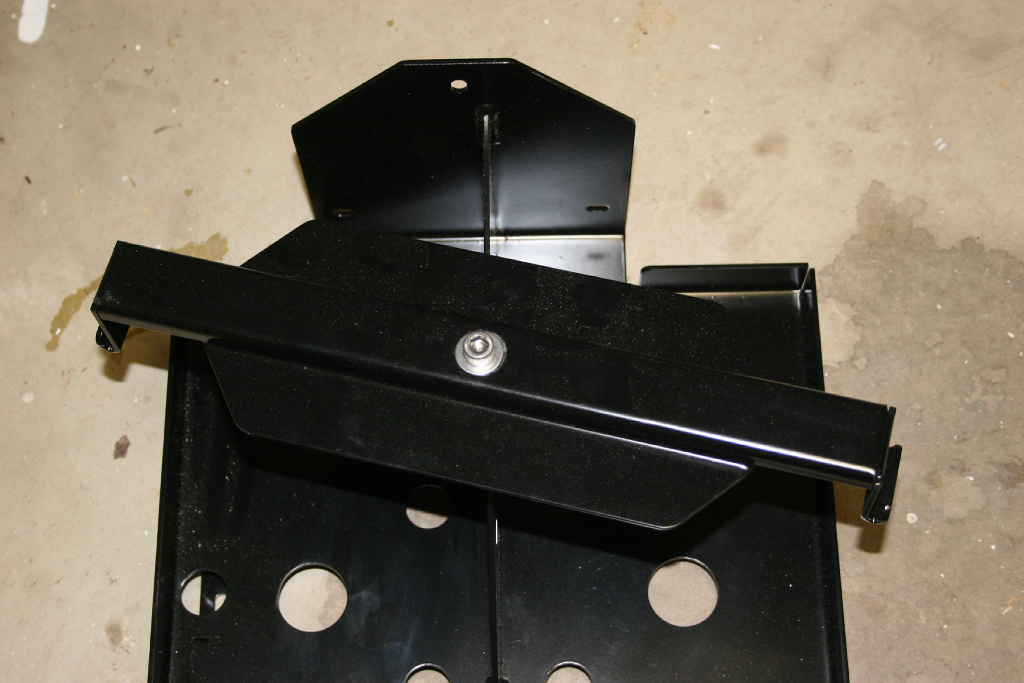
| 24. Remove the battery hold down from the top of the new tray and set aside. |
 |
 |
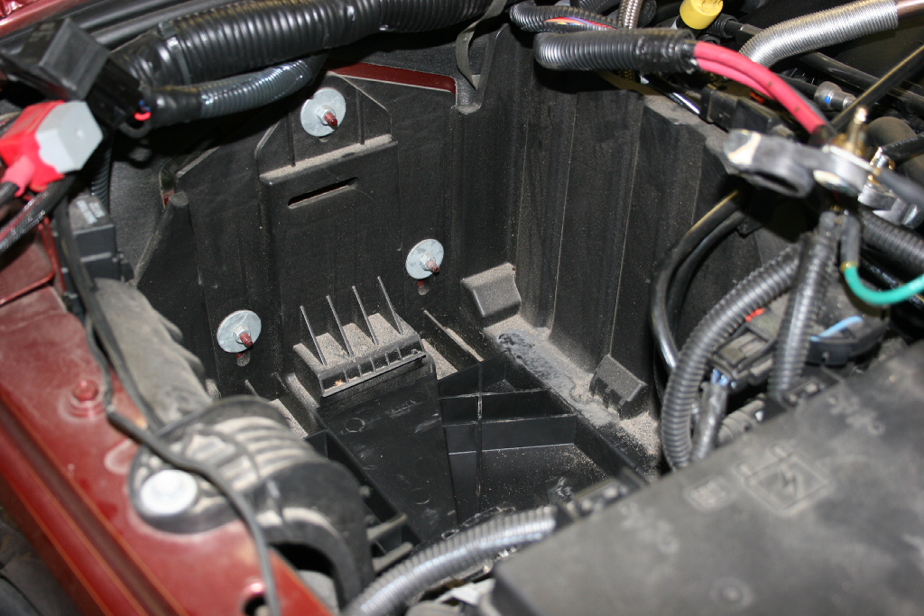
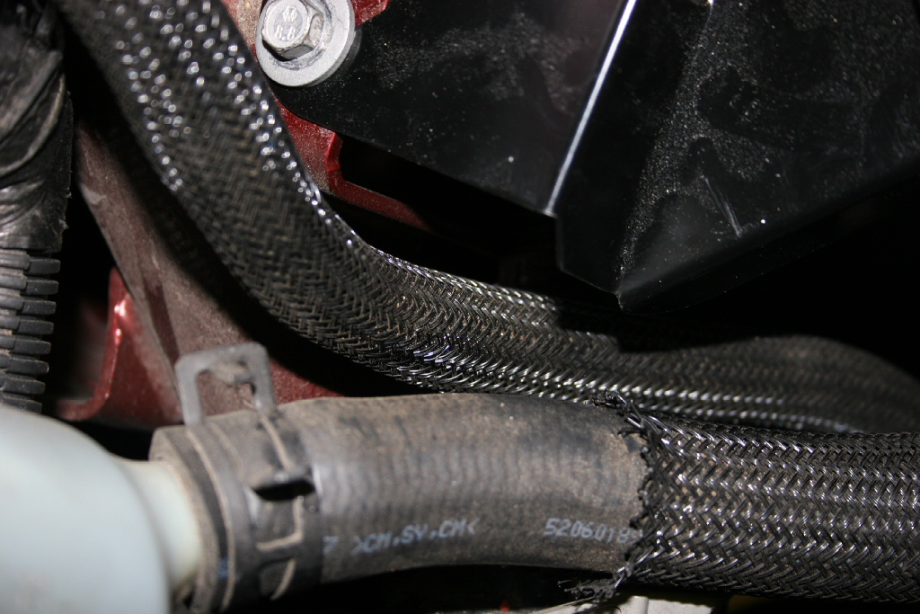
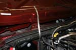
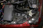
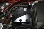
25. Slide the dual battery tray into position (nose first as shown in the picture). Slide the front underneath all wires. Watch for any pinched wires.
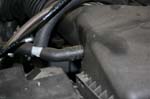
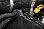
Note: The rubber heater hoses may need to be pushed towards the engine during installation of the tray. Once tray is in place, these hoses will sit on top/side of the tray. |
 |
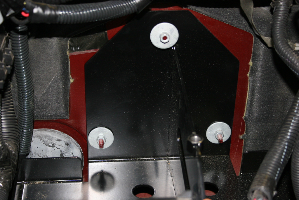
| 26. Loosely install the three nuts to hold the battery tray to the firewall. |
 |
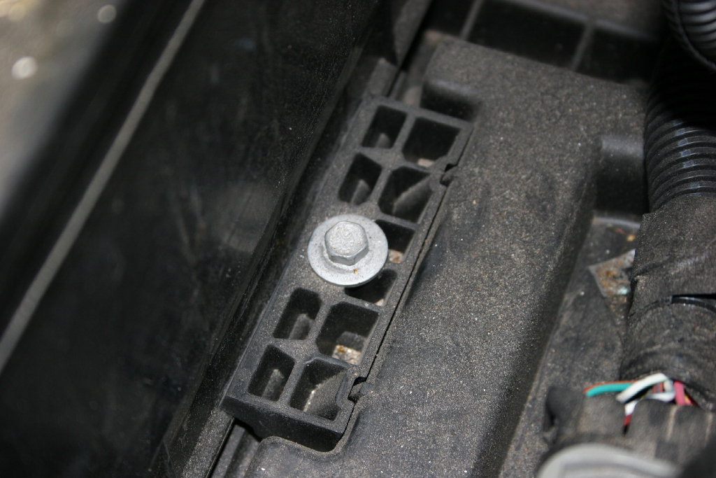
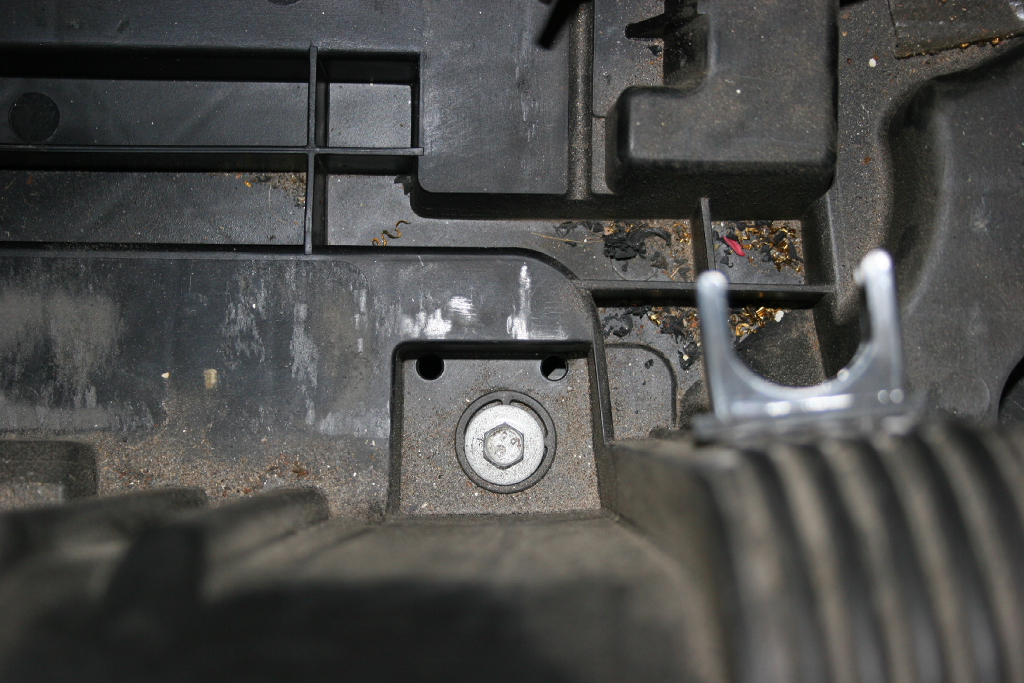
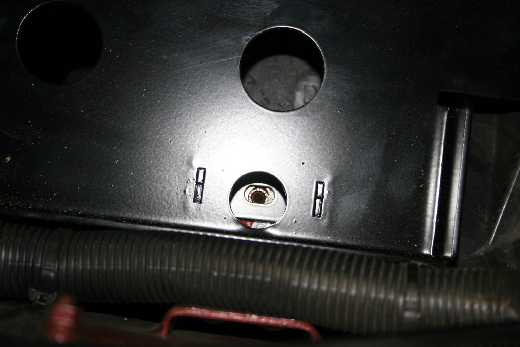
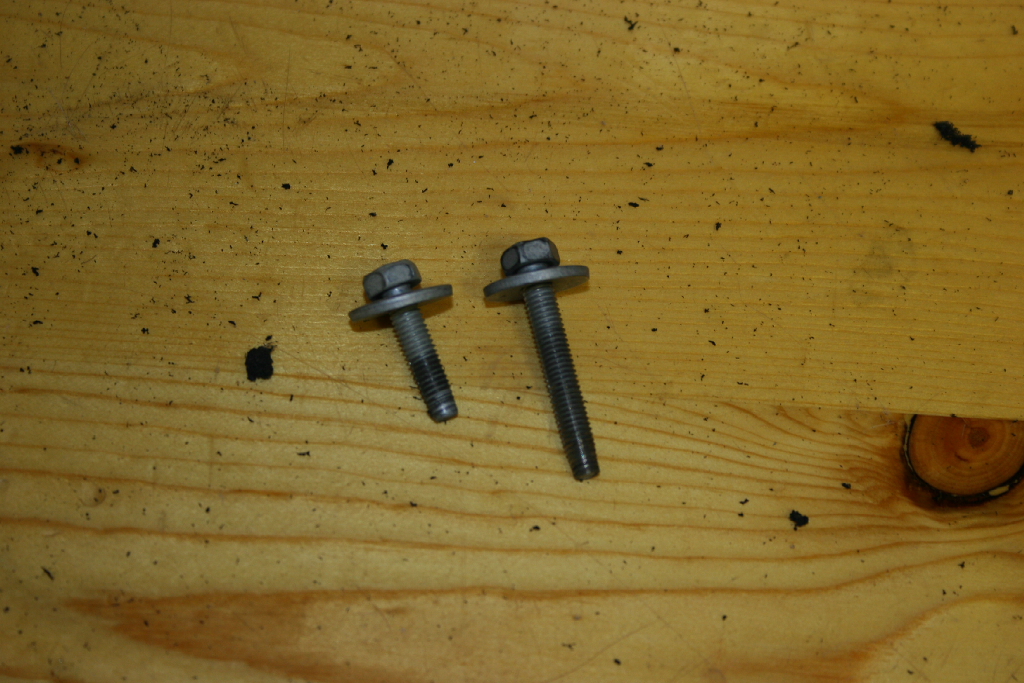
| 27. Reinstall the M6x35mm bolt (the same bolt you removed) through the base of the tray into the inner fender. Do not tighten down all the way. |
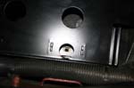 |
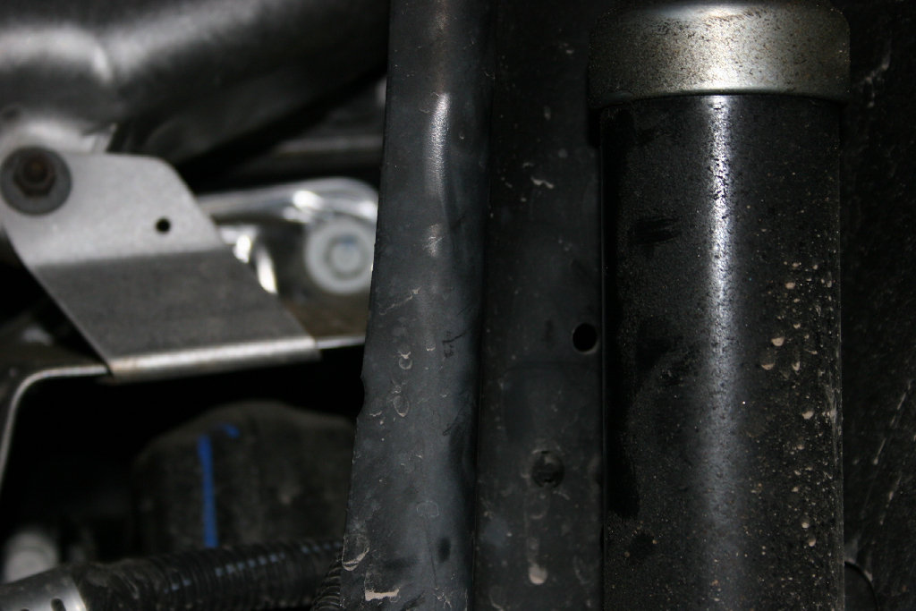
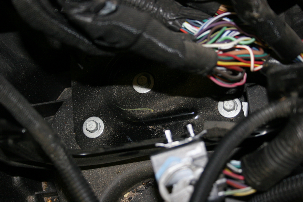
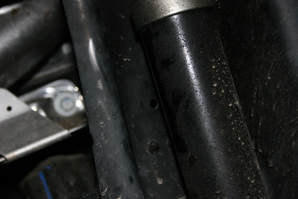
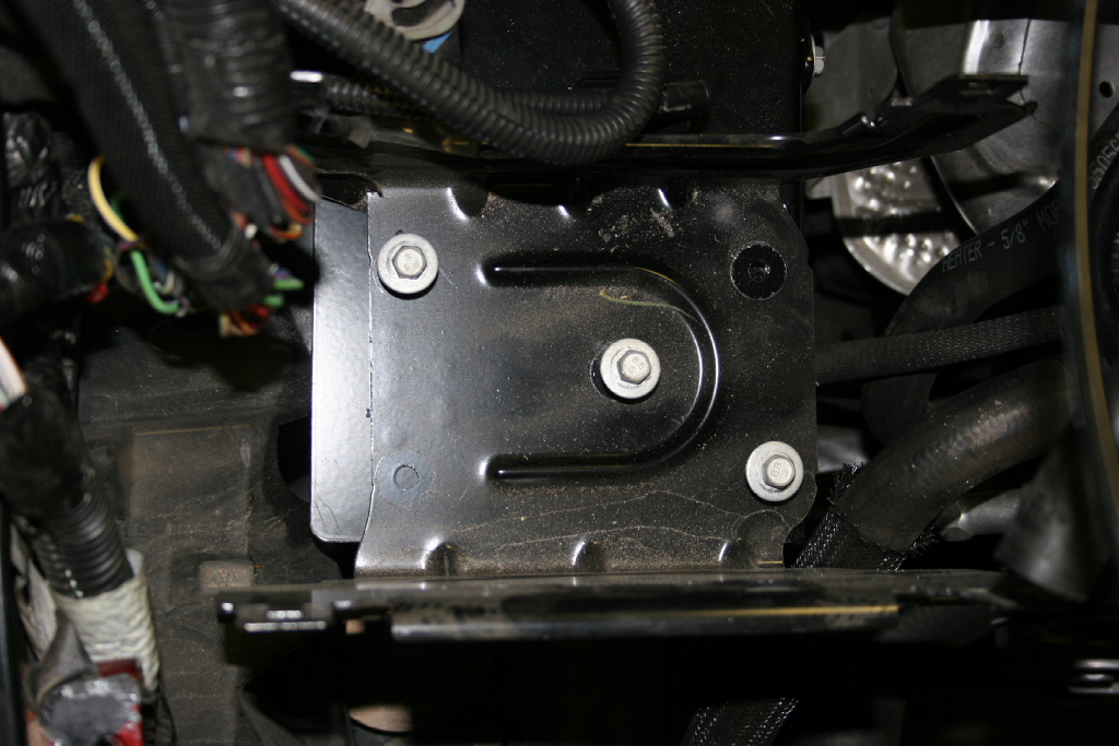
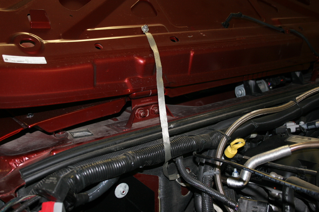
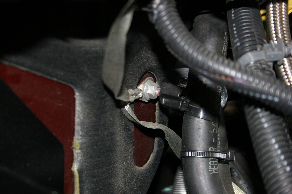
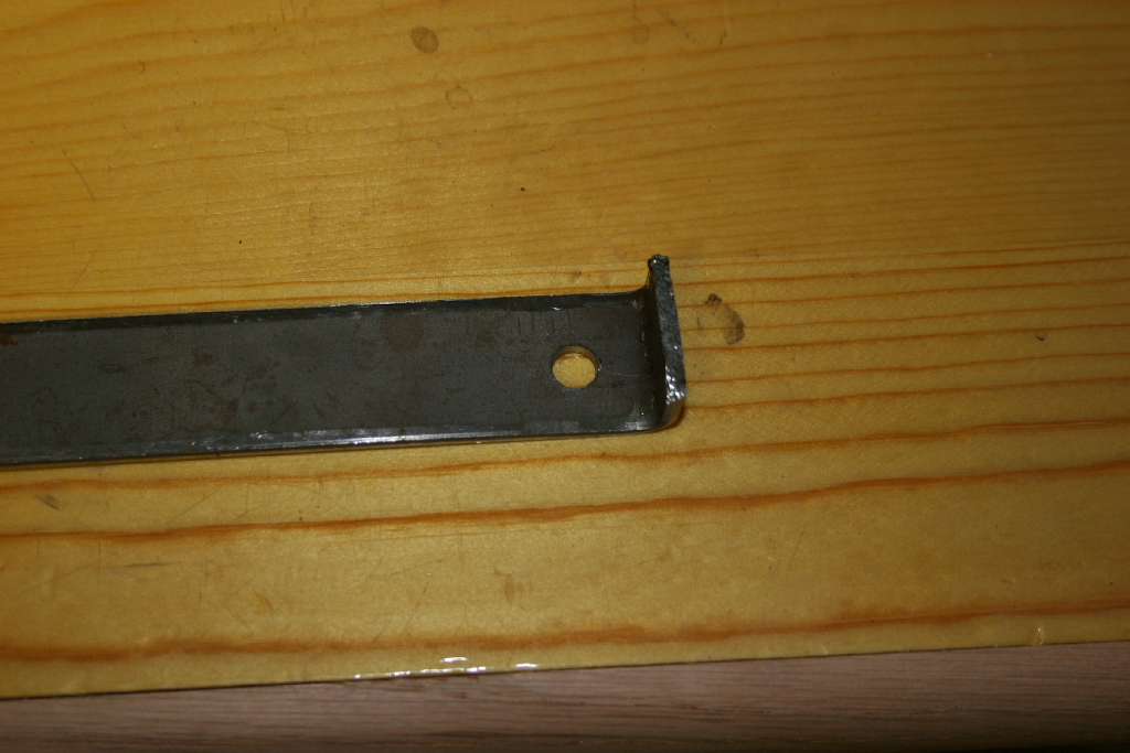
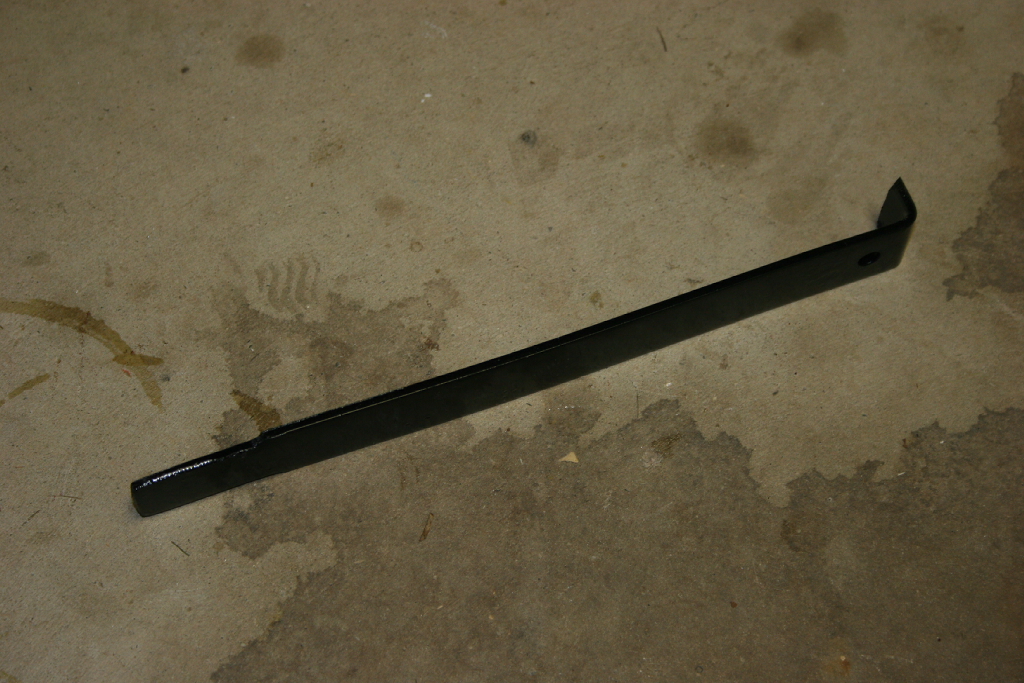
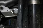
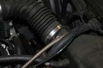
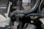
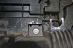
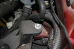
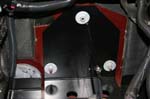
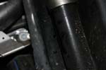
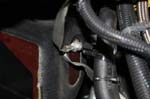
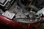
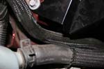
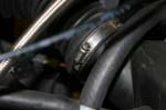
| 28. Install the battery tray support strap. You will need to get access to a hole that is located behind the left front shocks. You can just make out the hole on the side of the shock in the picture. |
 |
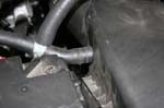
| 29. Once you have access to the hole shown above, insert one of the M6x35mm bolts through the hole, and thread into the battery tray support arm. One end of the arm has a threaded fastener installed (flat side towards shock mount), the other side is a hole. Do not tighten fully at this point. Now, from the engine bay, rotate the support arm up into position and line up the hole in the support arm with the threaded hole in the battery tray. Install one of the M6x35mm bolts all the way. Now return to the wheel well and tighten the bolt through the shock tower. I was not able to get good pictures of this, but the pictures in the instruction are great. |
 |
| 30. Tighten the three firewall nuts and the bolt through the base of the tray into the fender with a 10mm socket. |
|
|
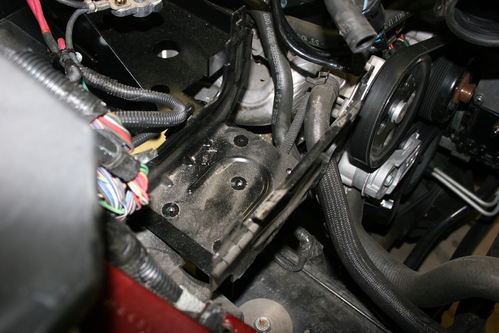
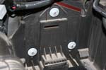
31. Place the TIPM support bracket in position on the dual battery tray front lip and see which holes line up. Re-install four M6x25mm bolts through TIPM support bracket into threaded holes on dual battery tray front lip. The holes that the bolts came out of on mine did not line up with the same holes on the new tray, but I fall into the note below.
Note: 2007 and early 2008 models use a metal TIPM support bracket and will only use 3 bolts to mount TIPM tray. |
 |
 |
 |
| 32. Reinstall the TIPM onto it's bracket. Make sure your don't pinch any wires, and everything slides into place. This can be a little difficult and requries a little pressure. If you can't push it down, check to make sure you don't have anything pinched, and that you are lined up with the bracket. |
 |
| 33. Reconnect the large electrical connector. Ensure that the lever is all the way back and latched. Push the connector back onto the side of the TIPM bracket. |
 |
| 34. Reconnect the electrical harness that was on the side of the battery tray before. Ensure that the red tap is pressed back in once it's connected to lock it together. This connector kind of just sits out in the middle of nowhere and will have to be addressed later. |
 |
| 35. Reconnect battery ground wire to stud on inner fender with a 10mm socket. |
|
| 36. Reconnect the wire harness to the evaporative purge solenoid. Ensure that the red tab is pressed back in once it's connected to lock it together. This just sits between the batteries and the TIPM and will have to be addressed later. |
 |
 |
| 37. Reinstall the power steering bracket and reservoir with a 10mm socket. |
 |
| 38. You will need to relocate, or insulate the hood ground strap. This will lay across the battery if you do not move it. |
 |
 |
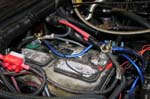
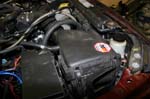
| 39. Install the batteries. The tray is designed to hold two Optima batteries, but for the time being I reinstalled the stock battery. It is a very hard fit. I had to disconnect the locker relay bracket from the firewall and move it up, so that the battery would fit. I do not know if this is an issue with the Optima's. |
 |
 |
| 40. Install the battery hold down bar on top of the batteries. The bolt requires an allen wrench, that I didn't have in any of my sets. I had one laying in a drawer that fit, but I don't know what size it was. I will replace this bolt with one I can put a wrench on. |
 |
| 41. Reconnect the power leads to the battery, or install battery management system as per the manufacturers instructions. I just rehooked the current leads to the repositioned stock battery. You may have a wire tie holding your leads together that needs to be cut. |
 |
 |
| |
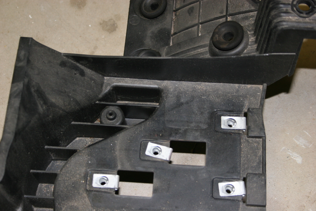
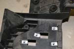
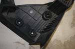
| The Benchmark Designs dual battery tray is supposed to come with a new bracket for the air box to be mounted to. I have not yet received the bracket, but looking at the M.O.R.E. dual battery tray pictures, and at the factory battery tray it was easy to cut the air box mount section off and reuse it. |
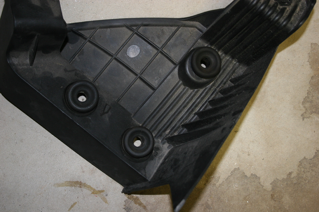
| 1. Cut along the back side of the wall that seperates the air box mount from the rest of the battery tray. |
 |
 |
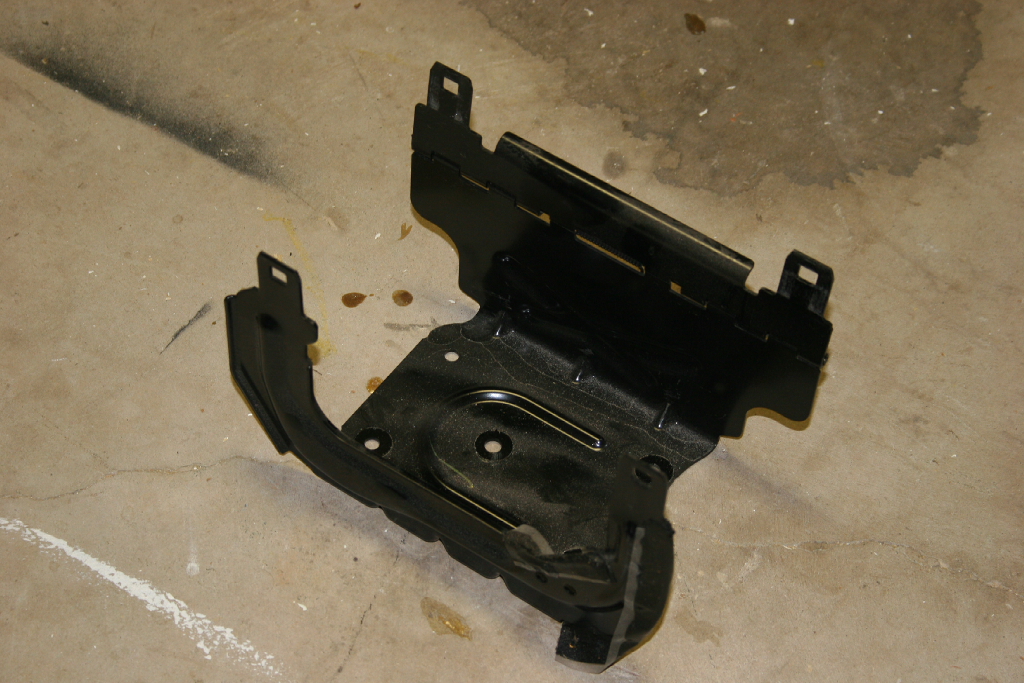
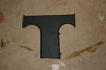
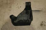
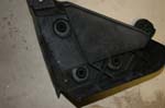
| Cut out section. |
 |
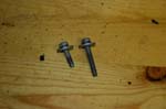
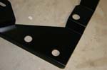
| 2. Reinstall the air box mount in the vehicle utilizing the two mount tabs. I used the last M6x35mm bolt, and the one remaining M6x25mm bolt from the TIPM that I did not use. If you have a newer JK, you may need to go get a M6x35mm bolt and washer for this. |
 |
 |
 |
 |
| 3. Reinstall the air box onto the rubber grommets. You may need to put your hand underneath to help hold the bracket when pressing down on the box to get the pins to slide into the grommets. |
 |
| |
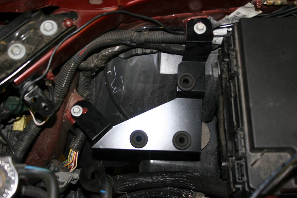
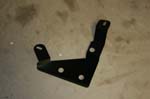
| 42. Now we need to install the new support for the air box. |
 |
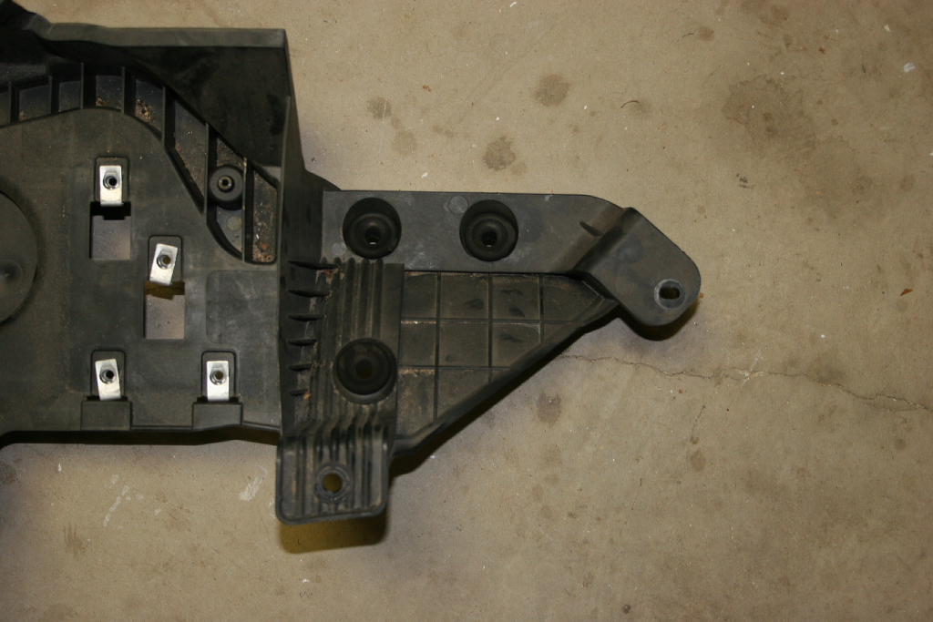
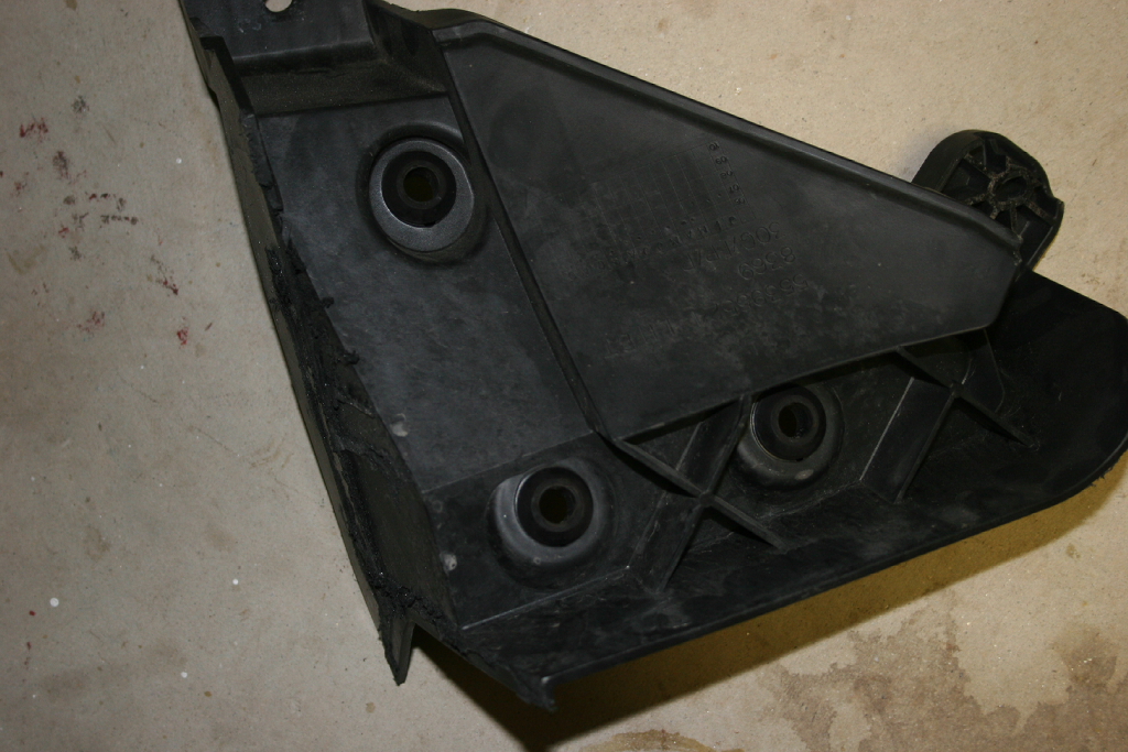
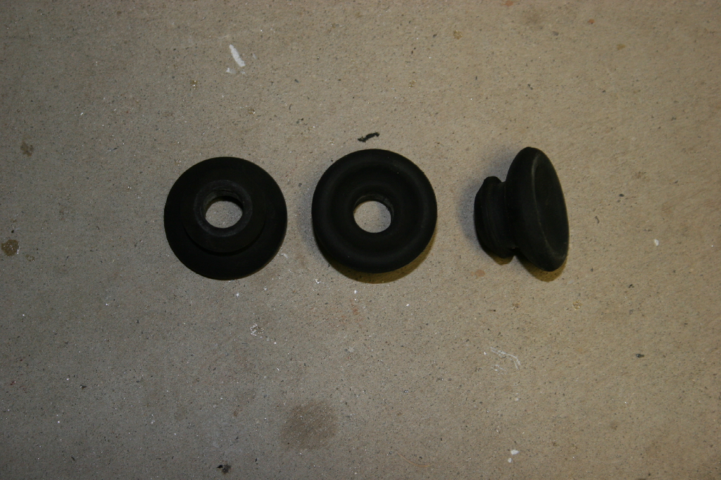
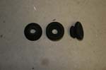
| 43. Remove the three gromets from the factory battery tray. They may just pull out, but if not you can flip it over and push them out from behind. |
 |
 |
| 44. Install the grommets in the Benchmark air box support. |
 |
 |
 |
| 45. Now you can either install the support on the air box and then bolt it in place with the remaining OEM screws, or you can install the support in the Jeep and then press the air box into it. I recommend installing the bracket first, and checking your clearance between the power steering hoses and the edge of the bracket. Then remove it and install it, install on the air box and reinstall the entire assembly in the Jeep. |
 |
 |
| The two 10mm bolts that hold power steering reseivour allow for enough adjustment to clear the lines away from the edge of the air box support. |
 |
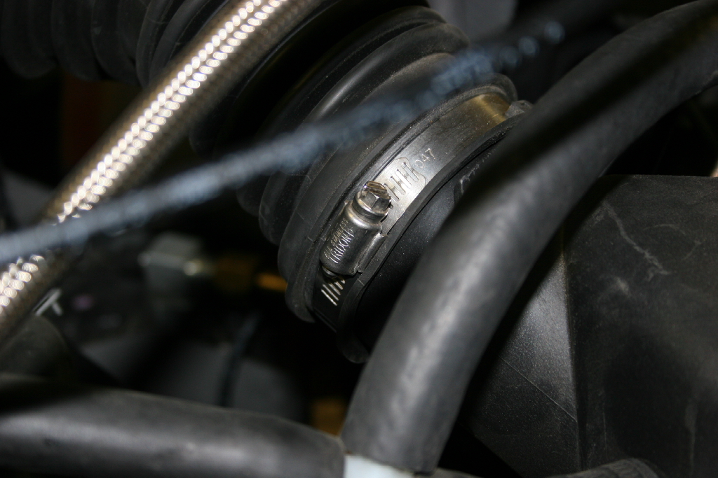
| 43. Reconnect the the air tube to the air box and tighten the hose clamp with a flat tip screwdriver. |
 |
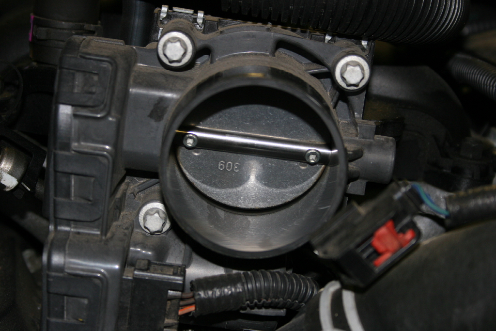
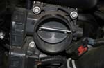
| 44. Reconnect the air tube to the throttle body and tighten the hose clamp with a flat tip screwdriver. Recconect the wire harness to the IAT Sensor and push the red lock tab back into position. |
|
|
|
|
| 45. Reinstall the crankcase vent hose to the side of the air box. |
 |