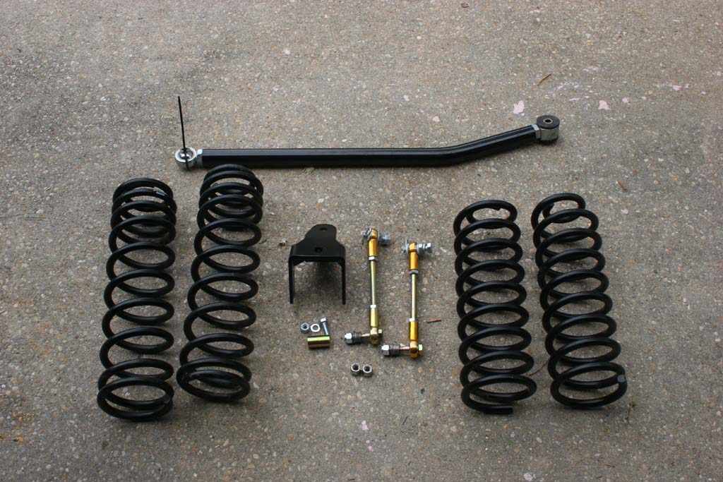
With the 2012 Jeep JK I decided that I would keep it simple this time, no fancy air systems, just old school springs and shocks. I removed the Teraflex 2.5" Budget Boost and finally installed the Rock Krawler 2.5" stock mod that I had hidden away in the garage. I picked up a set of Bilstein shocks and reused some old parts from my Clayton kit that I had a while ago.
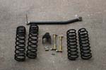
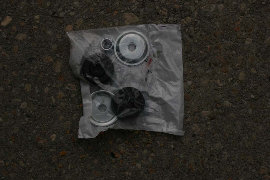
| Sort out your suspension lift parts: |
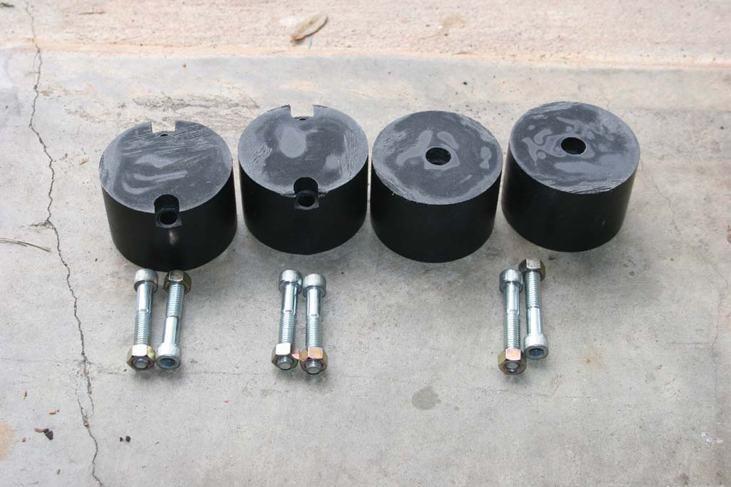
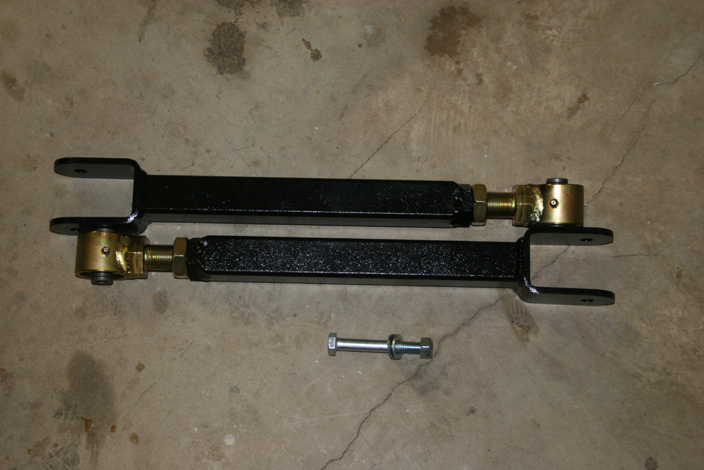
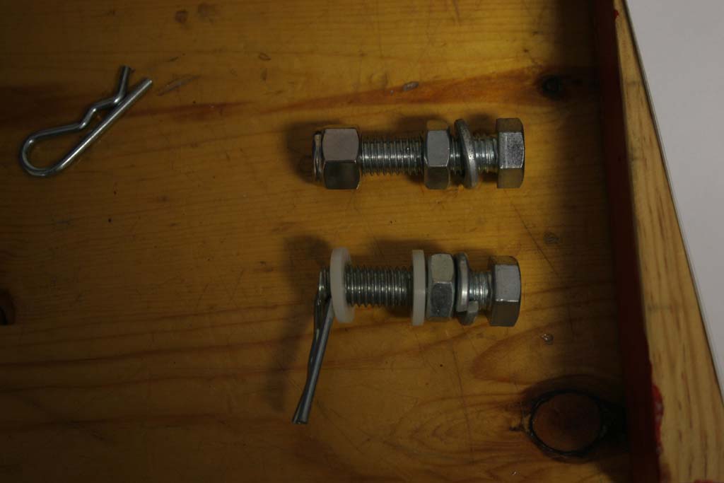
| Now is a good time to sort out all the suspension part to ensure the you have the nuts and bolts that belong with each part. I usually put them together to keep them in place. Example would be putting the bolt and nut that belong with a bump stop through the bump stop and putting it aside. A few times I have gotten into a project only to discover a missing bolt or part. Better to double check before than to get things torn apart and have to put them back together because you didn't have the right or all parts. |
 |
 |
 |
 |
| |
| Preparing the Suspension: |
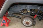
| Most of us will be doing this on the garage floor and won't have the luxury of a lift and axle jacks, so we will work on one section at a time. Blocking the tires that remain on the ground is important to keep the Jeep from rolling. Having a good set of floor Jacks to support the Jeep. I use a set of 6 ton jacks to hold the Jeep up. You will need to loosen and remove a few bolts prior to starting the real hard work. Like always if in doubt as to safety, or your abilities, get help, or take it to a reputable shop. |
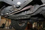
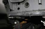
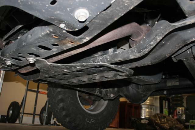
| If you have an automatic you will need to remove the front skid plate. The skid plate will come in contact with the front driveshaft during articulation. You may not need to do this step depending upon the type of skid plate installed. Some of the Jeeps have just a bar running across in this area to protect the transmission. |
 |
| |
| Front Installation: |
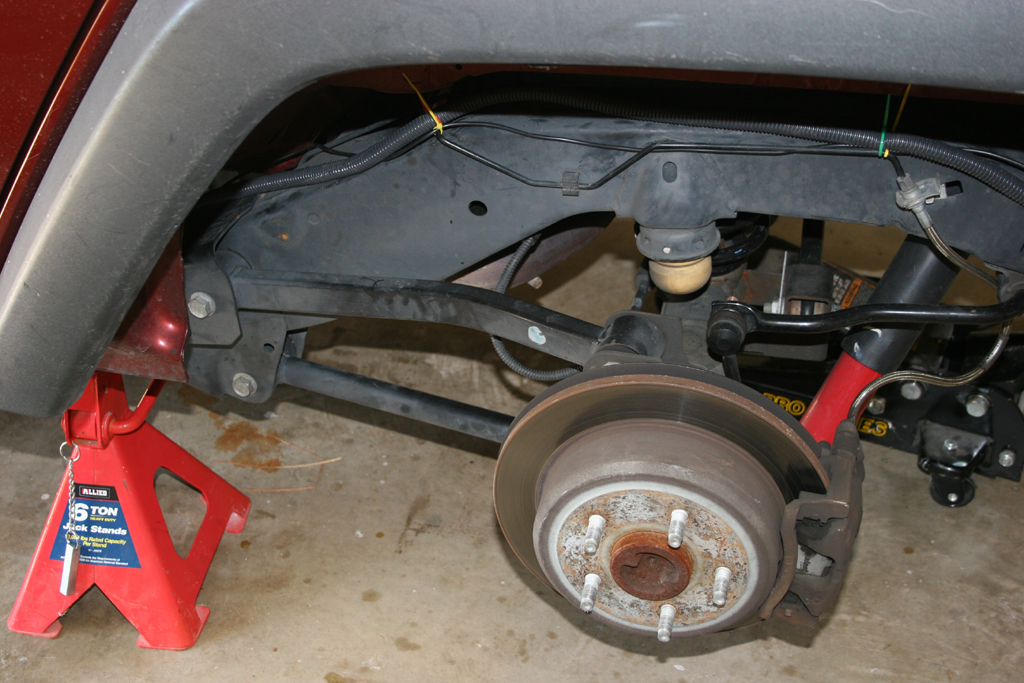
| Jack up the front axle and support with Jack stands in behind of the lower control arm frame mount point. Remove the tires |
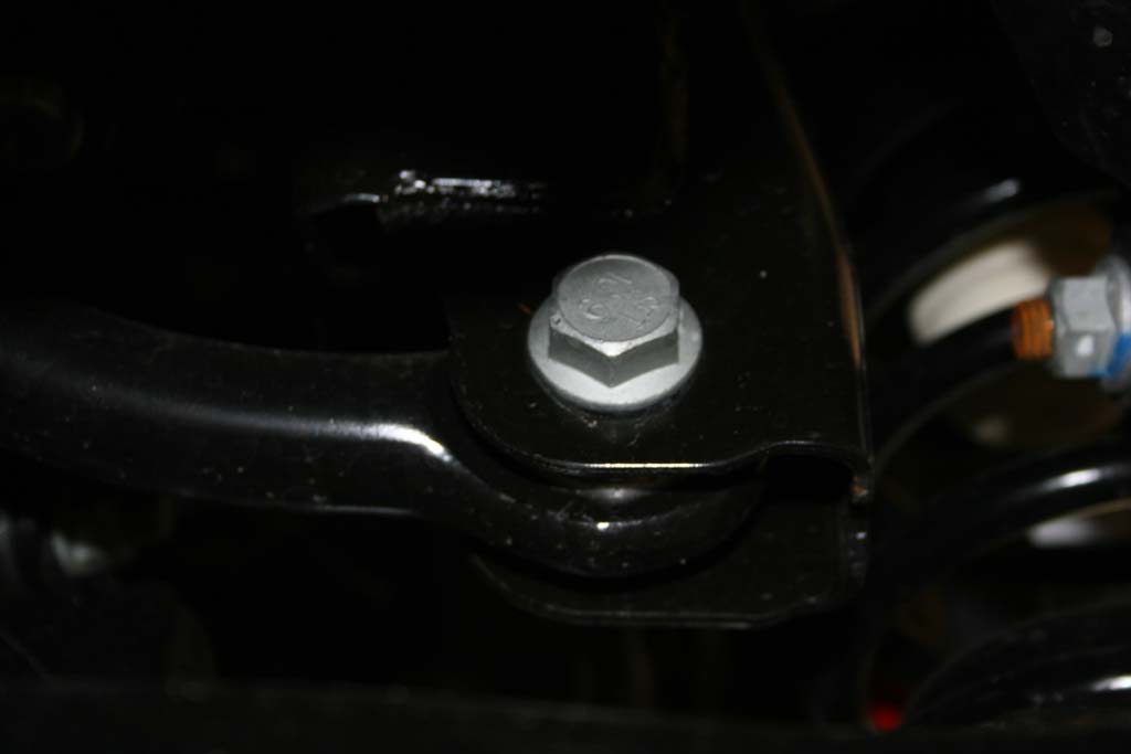
| 1. Loosen (DO NOT REMOVE) the bolts holding the upper and lower control arms. You will need a 18mm and 21mm socket and combo wrench. |
 |
 |
 |
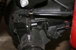
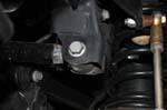
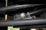
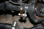
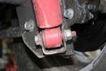
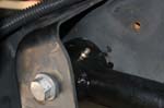
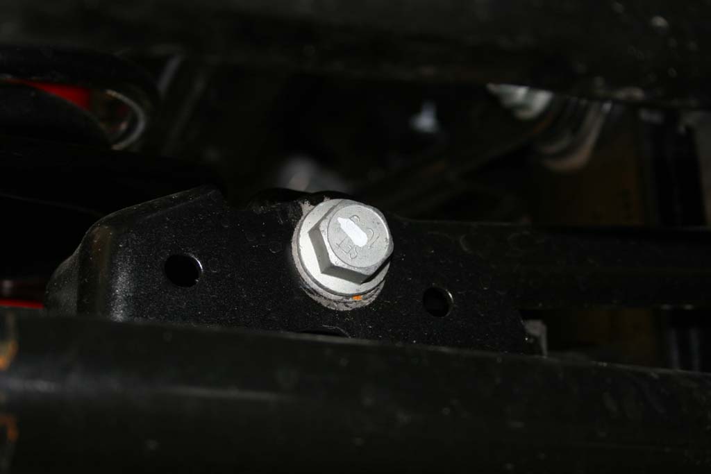
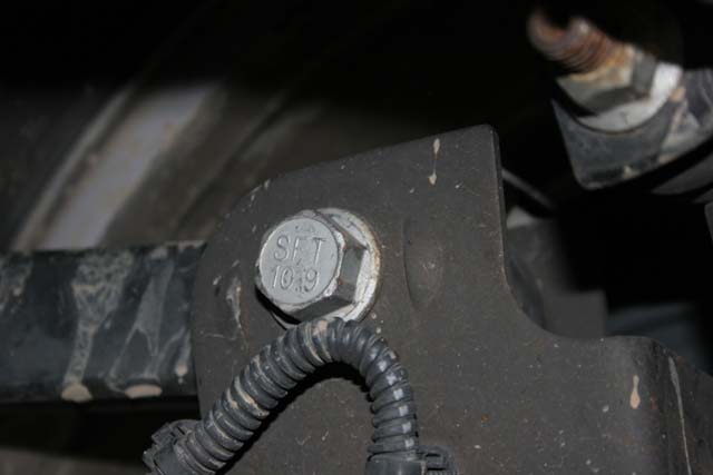
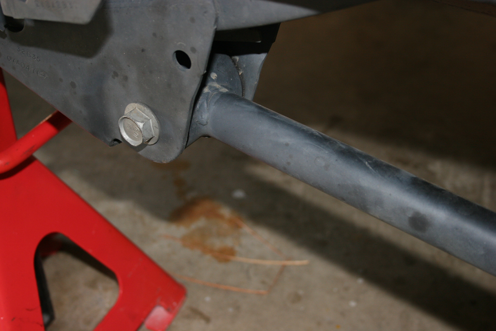
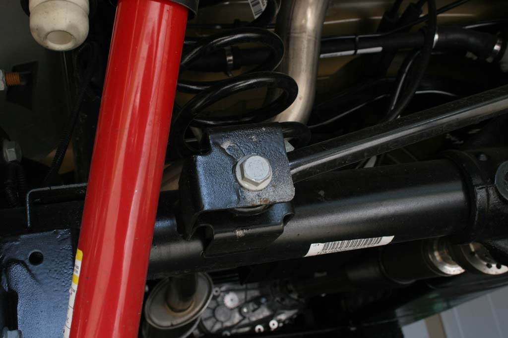
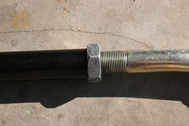
| 2. Loosen the front trackbar with a 21mm socket and combo wrench. |
 |
 |
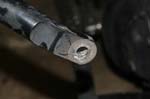
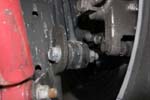
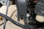
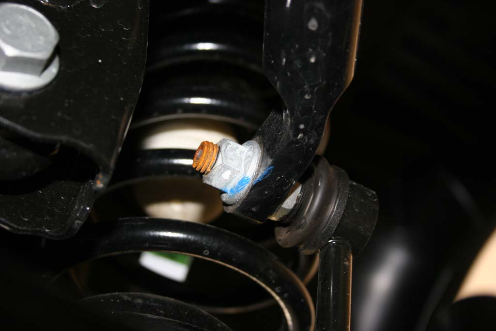
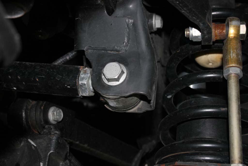
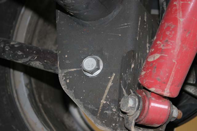
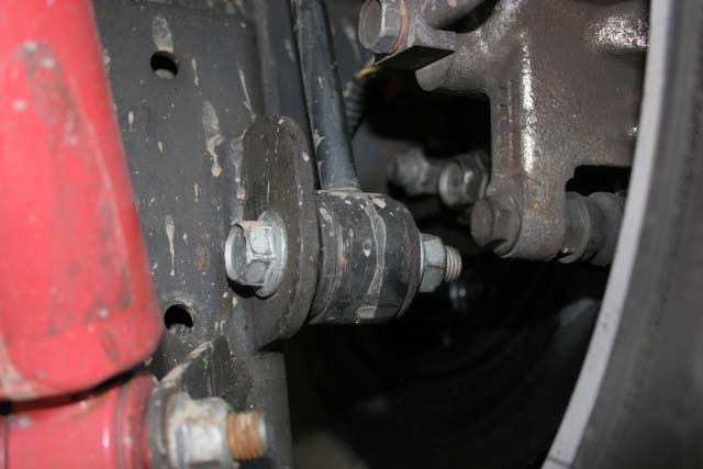
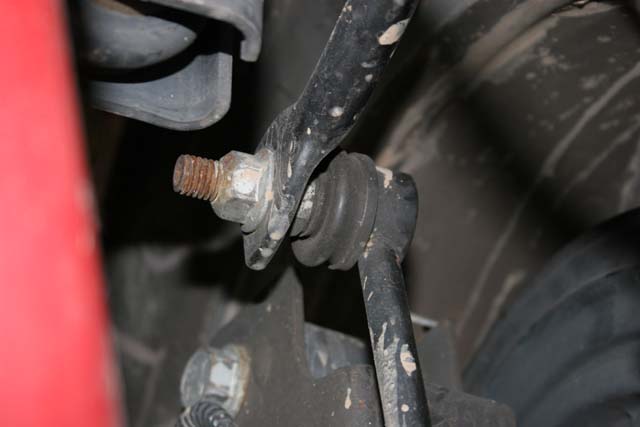
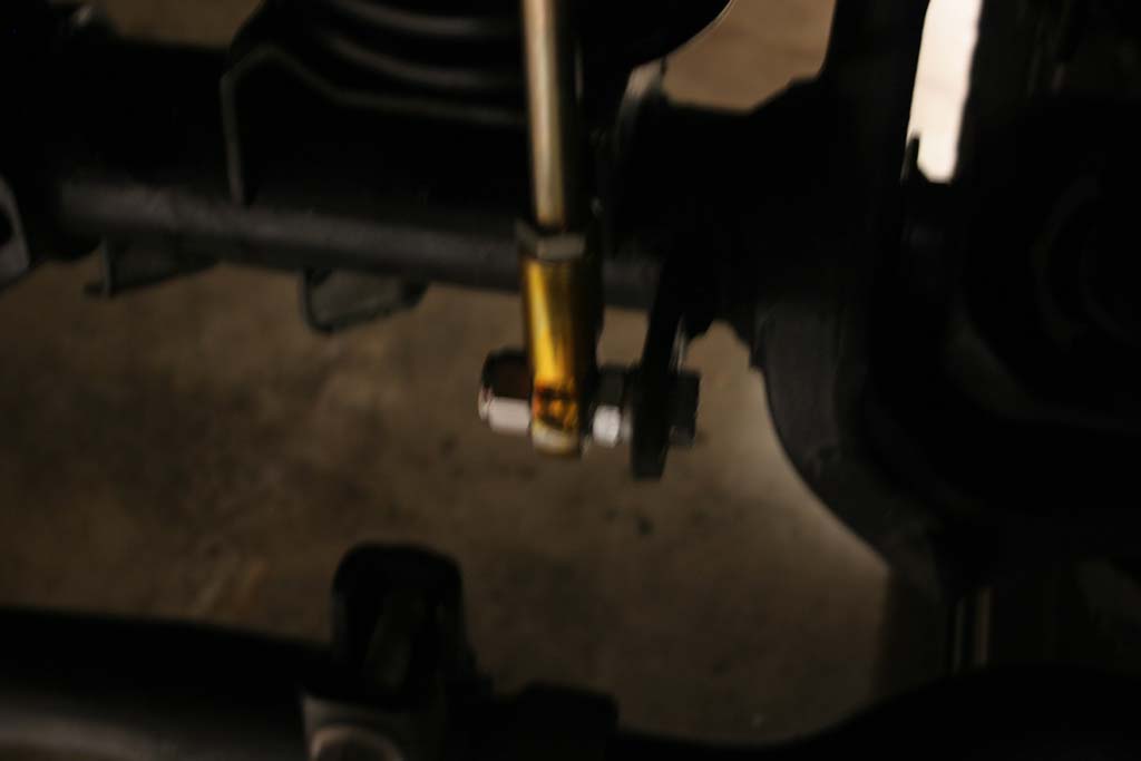
| 3. Remove the front anti-swaybar links with a 18mm socket and combo wrench for the lower bolt and a 18mm socket and 19mm combo wrench for the upper stud. |
 |
 |
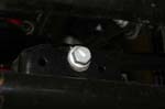
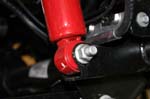
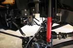
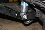
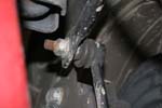
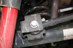
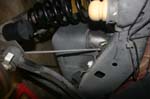
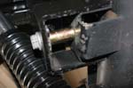
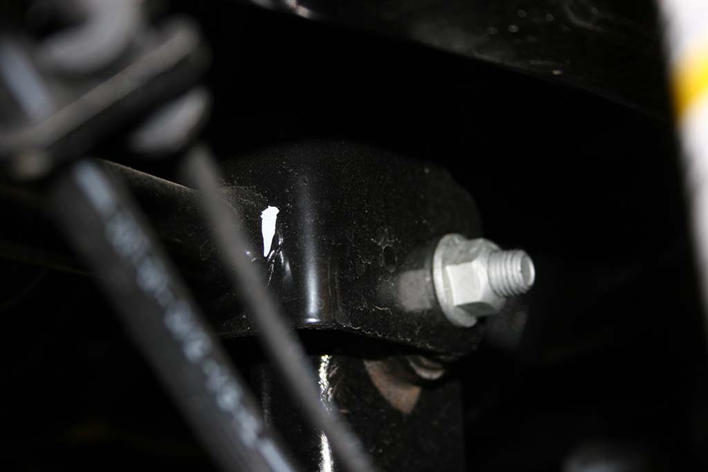
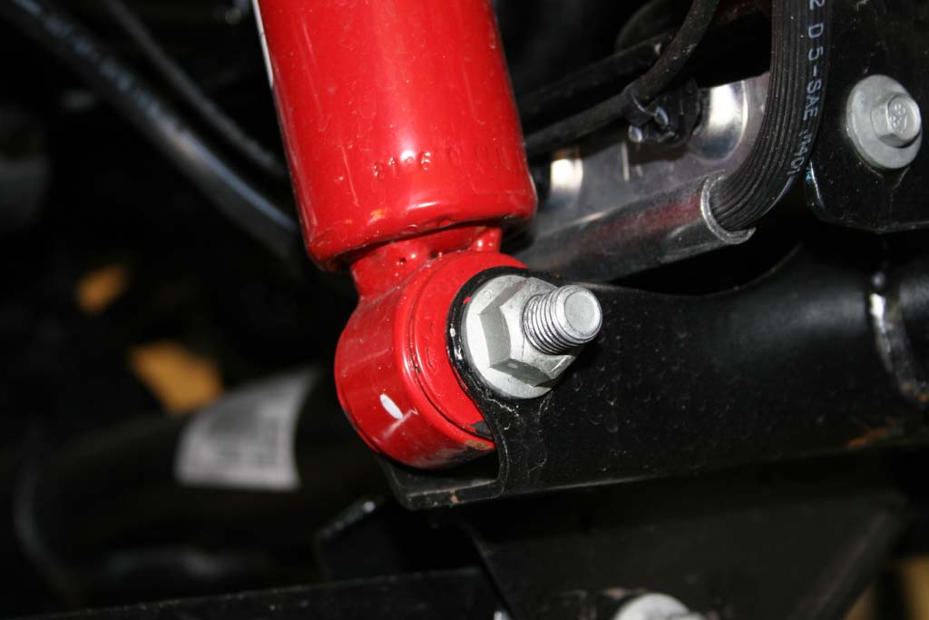
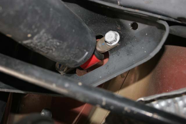
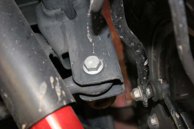
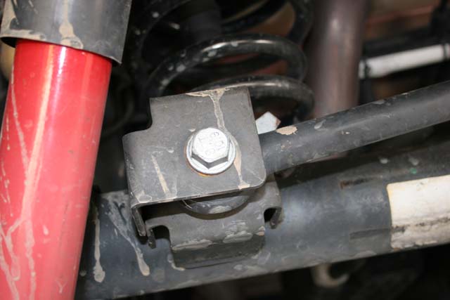
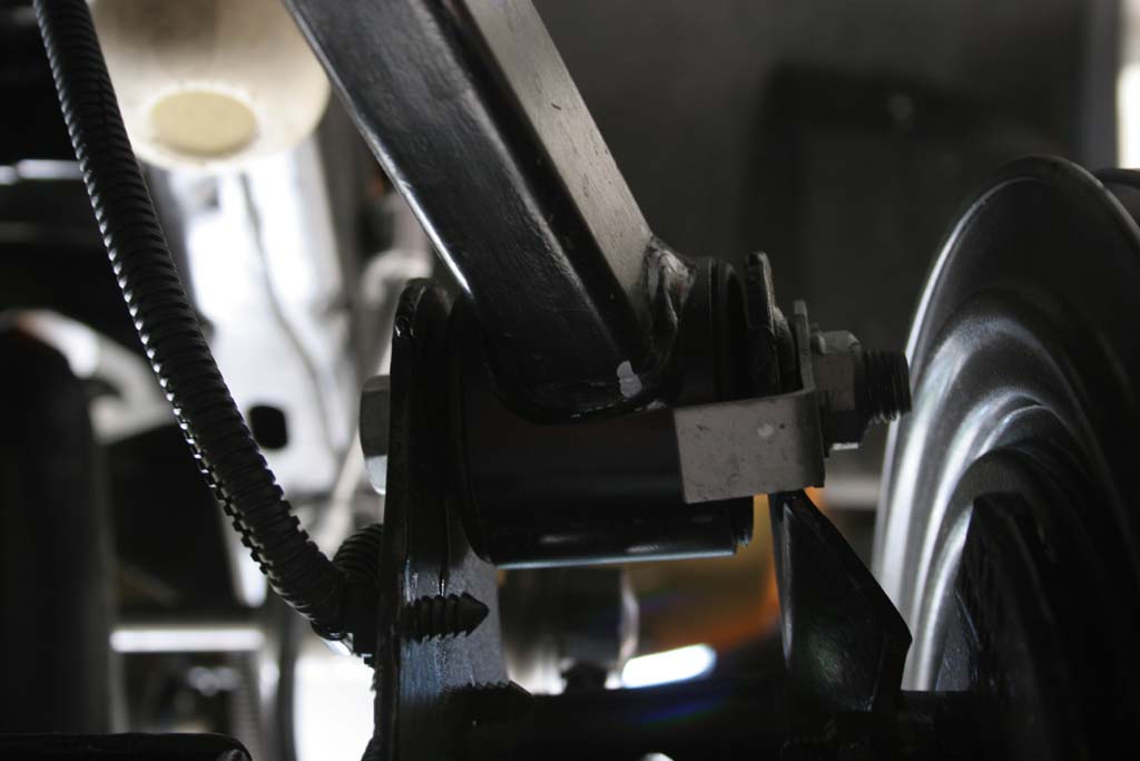
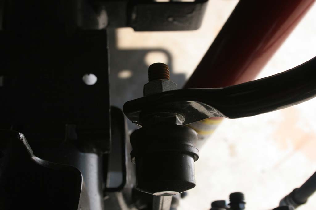
| 4. Remove the front shocks with a 18mm socket and combo wrench for the lower bolt, and a 16mm combo wrench for the upper nut. You can use a 5/8" wrench to hold the welded nut on the top of the shock while you unscrew the nut. |
 |
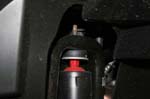 |
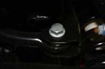
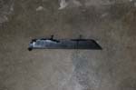
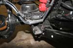
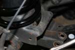
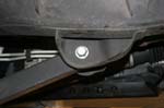
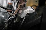
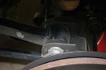
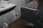
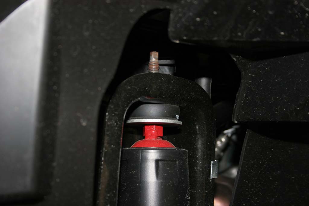
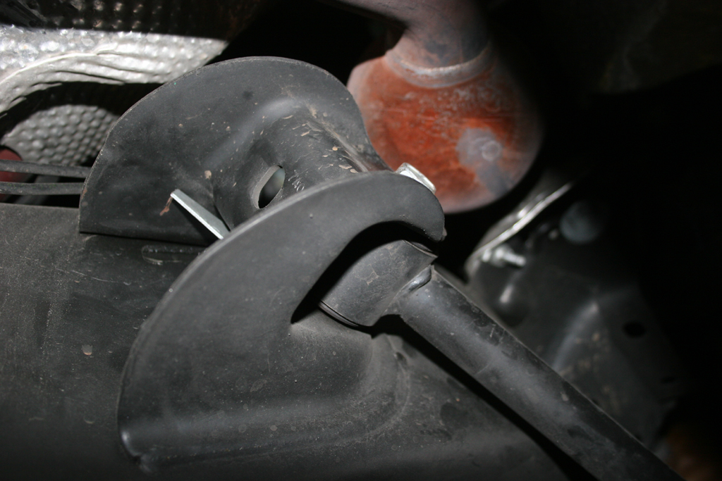
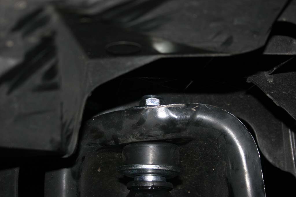
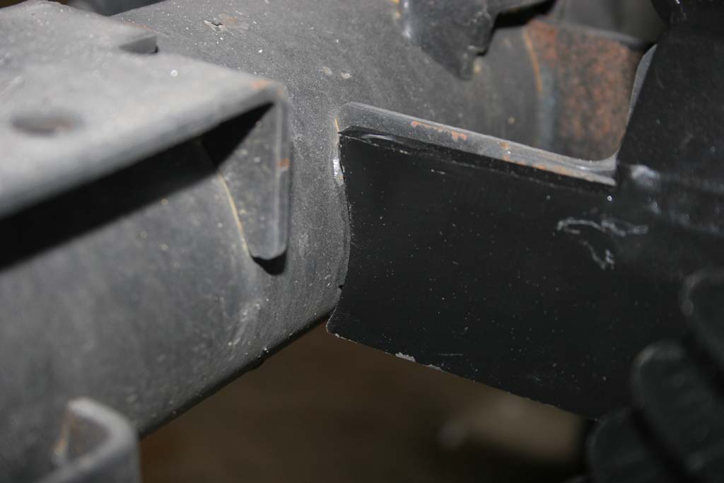
| 4a. The Passenger side on the 2012 JK's presents an interesting problem. The plastic tray sits nearly on top of the shock tower. |
|
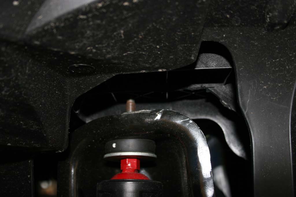
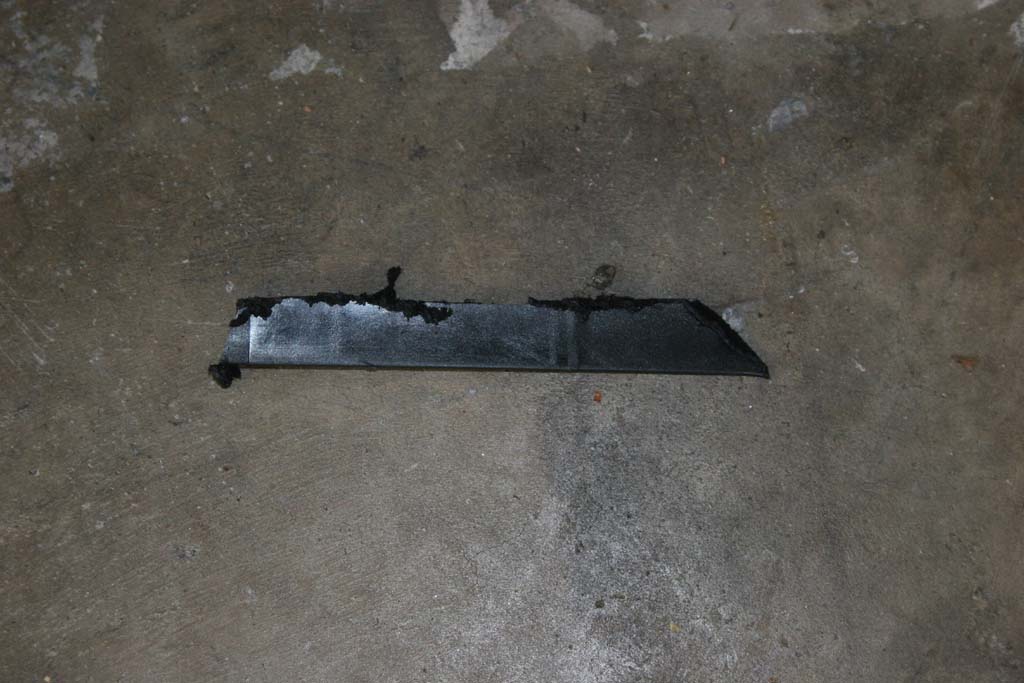
| 4b. Just use a Dremel tool, or a hacksaw blade to remove the plastic from just under the top webs and the length of the shock tower. Now you can easily get the 16mm combo wrench to the top nut on the shock. I did have to use another 16mm combo wrench to hold the welded nut on top of the shock to loosen up the top one. |
 |
 |
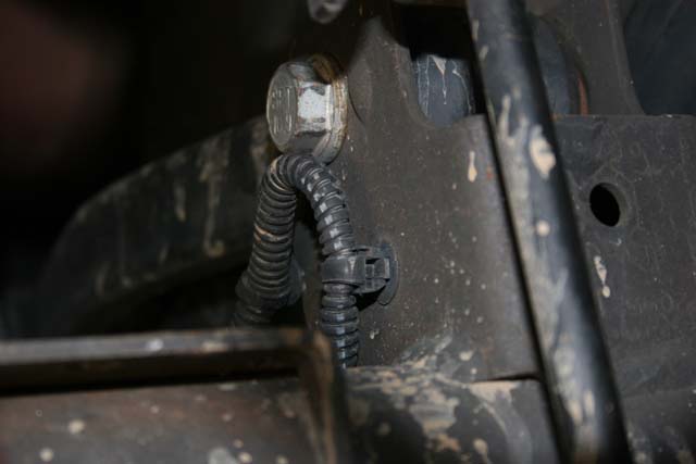
| 5. If you have a Rubicon model, unclip the locker line from the top of the differential. It is located on the side of the upper control arm. |
 |
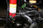
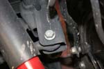
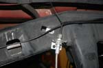
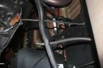
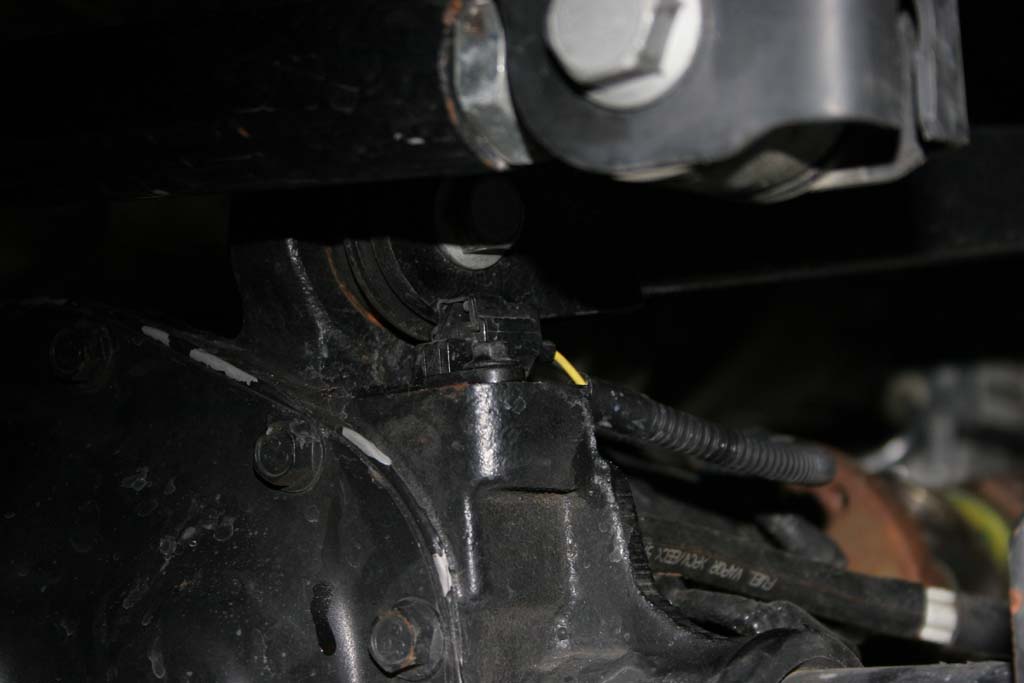
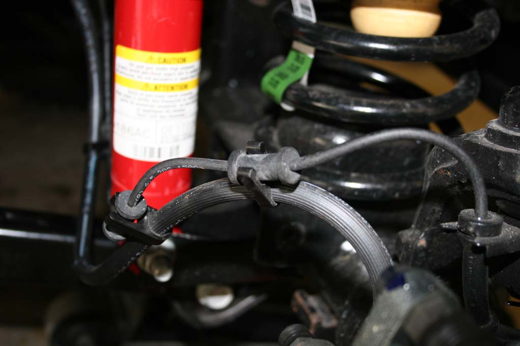
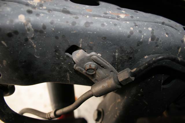
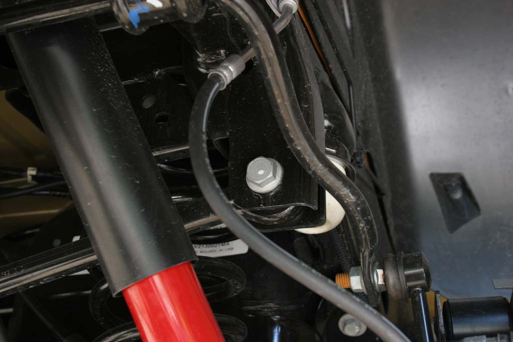
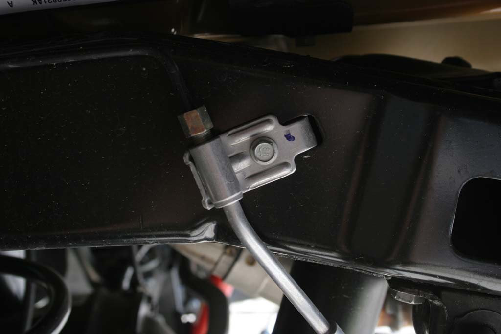
| 6. Unbolt the brake line brackets by removing the bolt with a 10mm socket. You do not need to do this on the 2012's, they made a slight change to the brake line in the front, see below. |
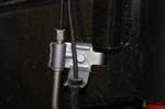 |
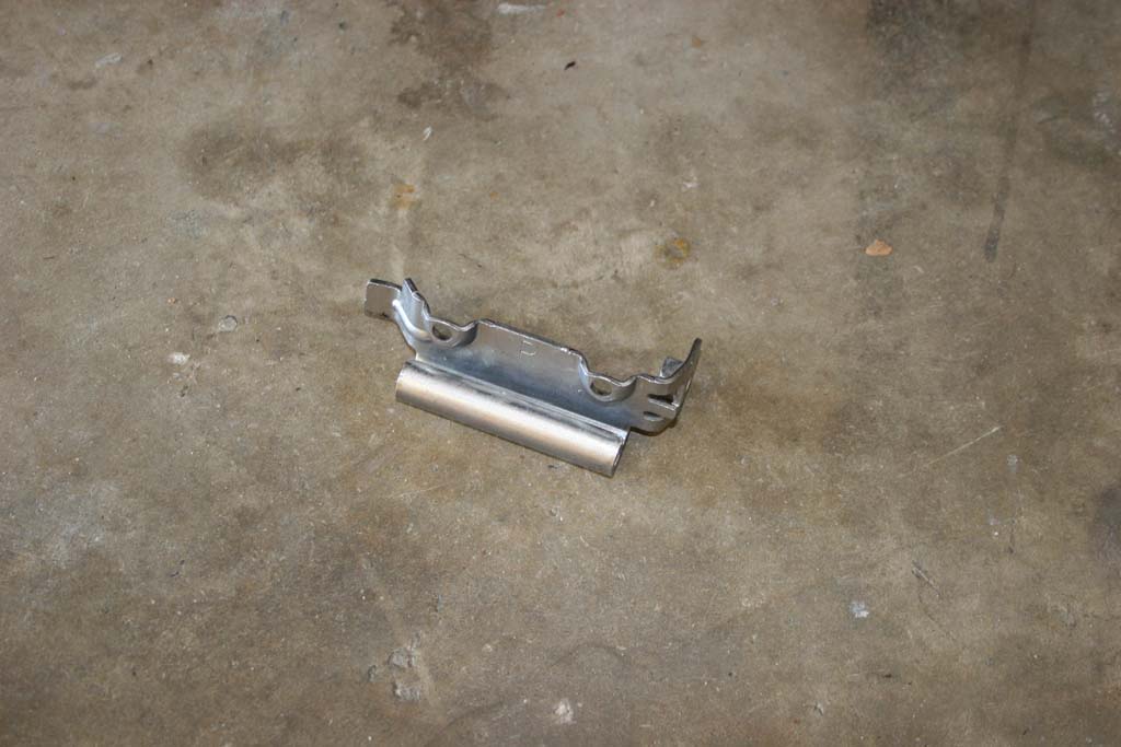
| 6a. Unbolt the brake line brackets by removing the bolt with a 10mm socket. Pull the bracket out of the hole that the tab on the bracket is intalled into on the inside. |
 |
 |
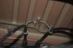
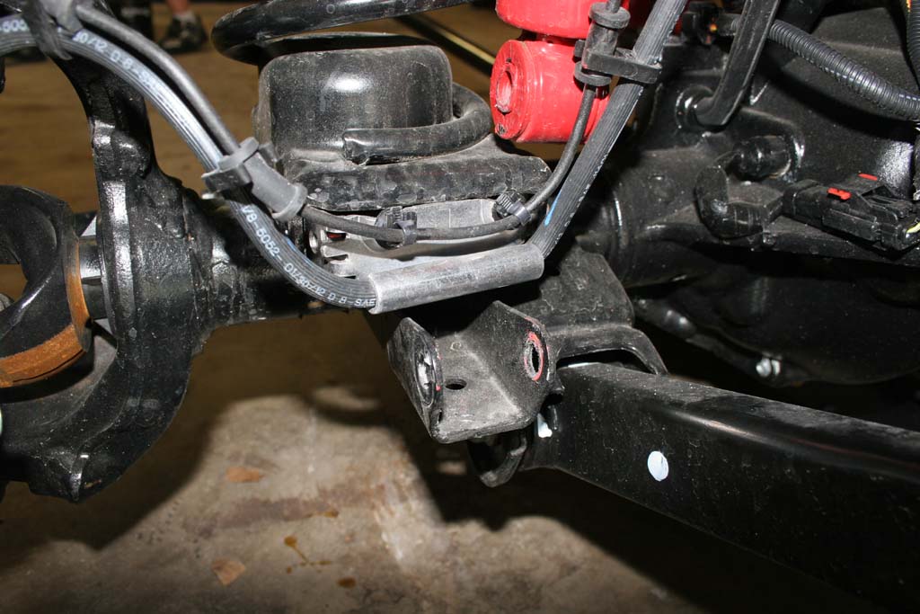
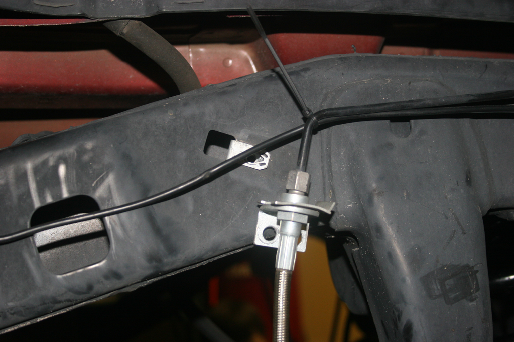
| 6b. Carefully cut and remove the zipties holding the ABS line to the bracket. Spray some silicone lube, or WD-40 into the bracket (coat it good). Work the brake line out of the bracket through the slot. It's tight, but once you get it started it does come right out. |
 |
 |
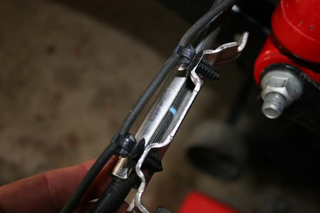
| 6c. Reclip the ABS line into the holders on the brake line. |
 |
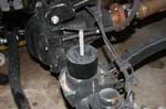
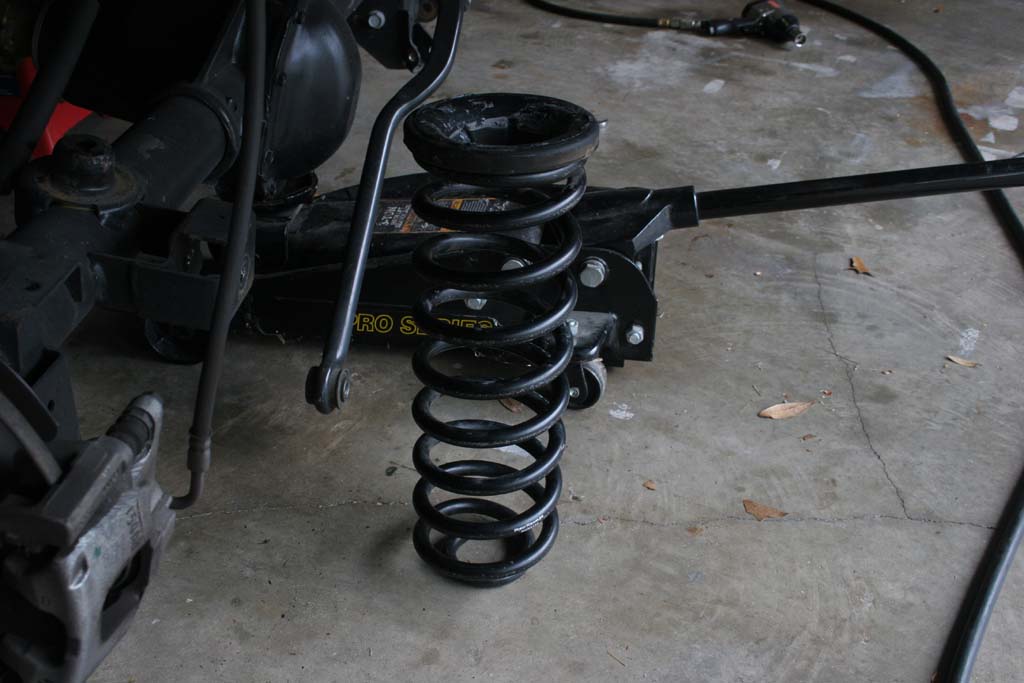
| 7. Lower the front axle far enough to remove the springs. Make sure you do not stretch the brake lines, abs wires, or locker wires. Remove the springs, noting which side they came out of. I have run into one instance where the springs had different part numbers. |
 |
 |
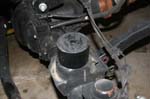
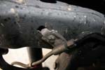
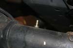
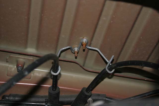
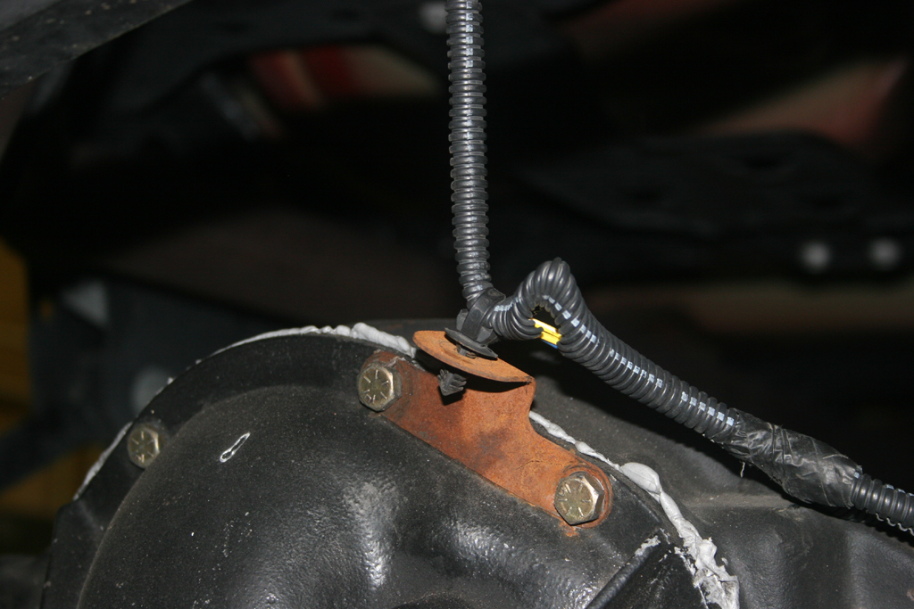
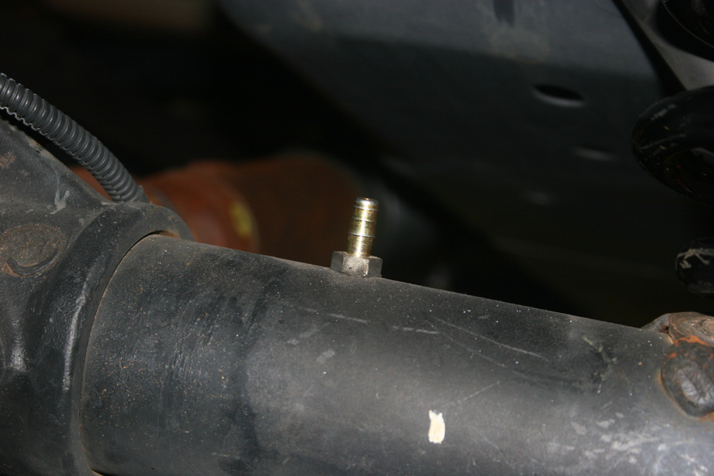
| 7a. The axle vent line will probably pull off it's fitting on the axle. Probably a good time to visit extending the axle vent fittings. |
 |
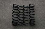
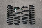
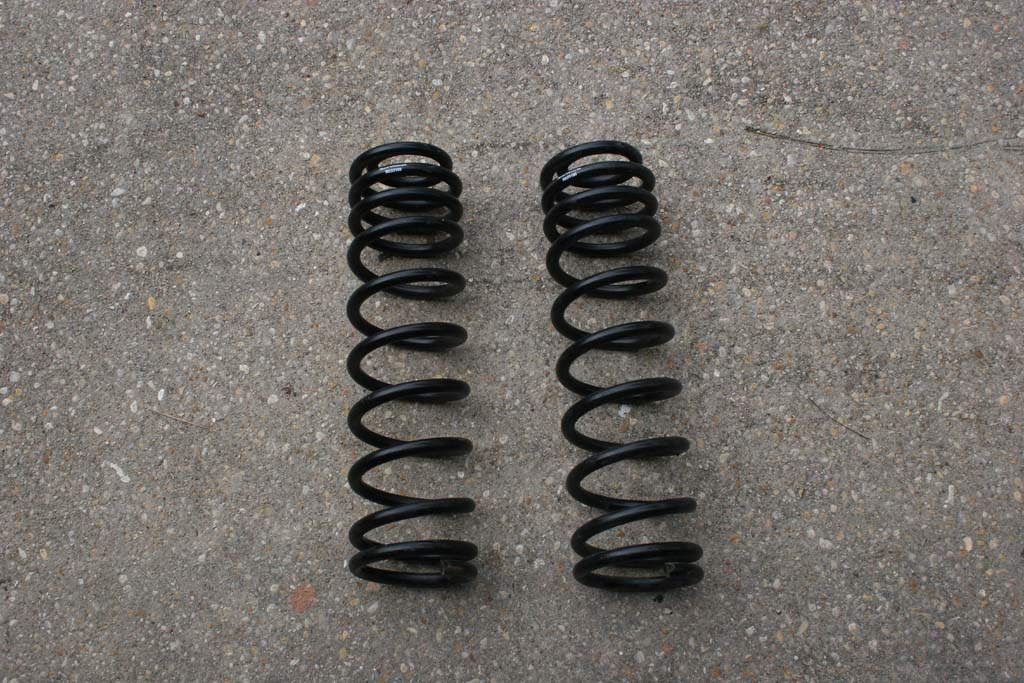
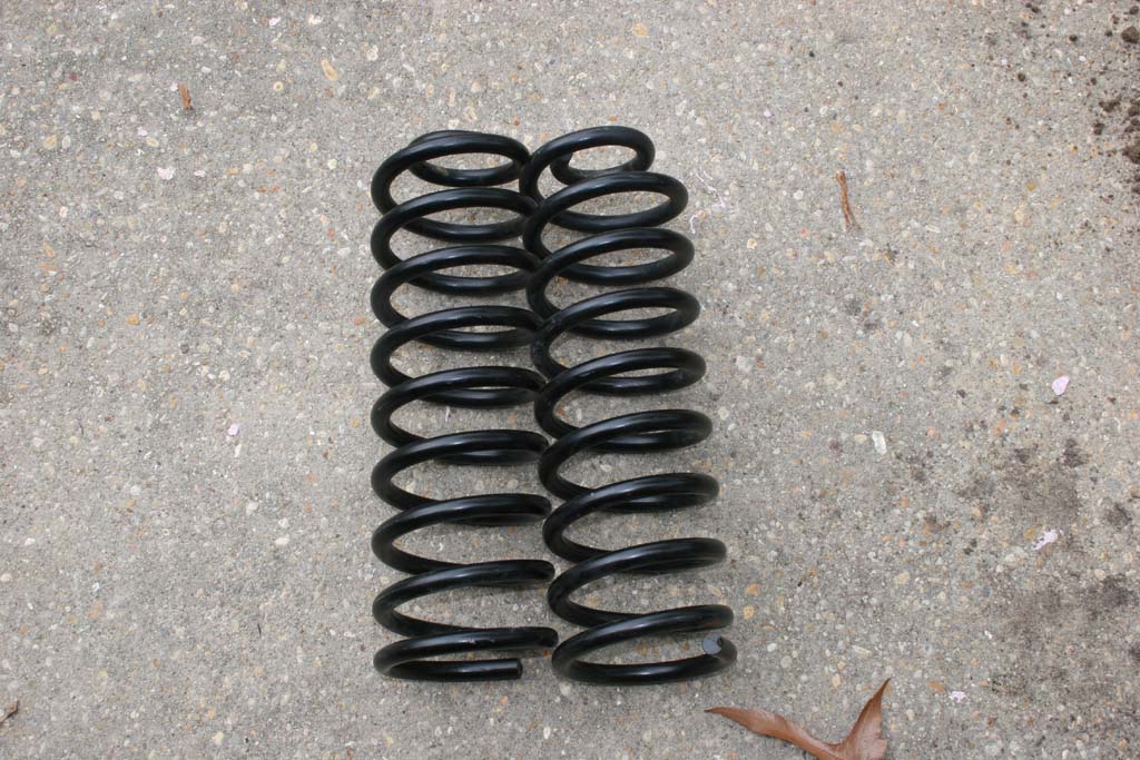
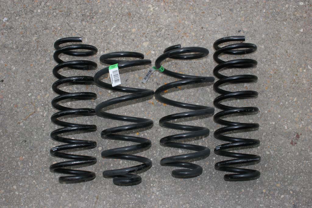
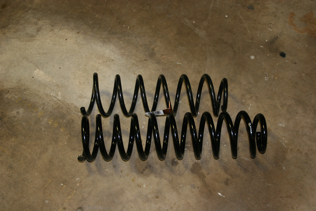
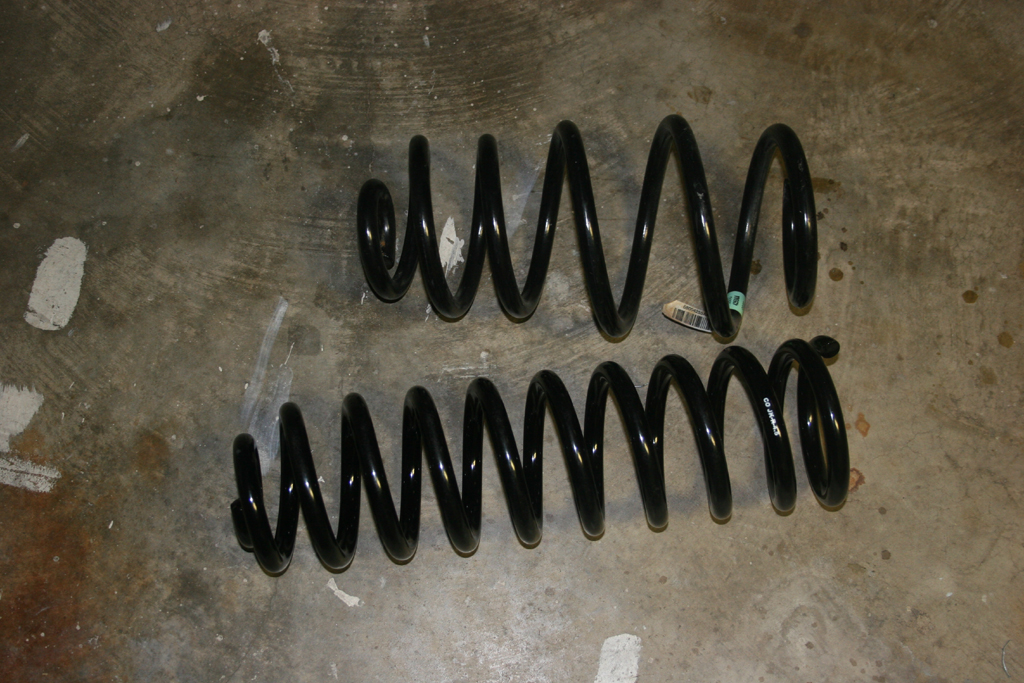
| Quick comparison shot. |
 |
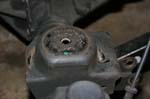
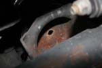
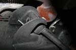
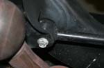
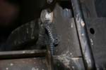
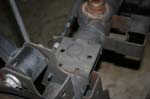
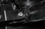
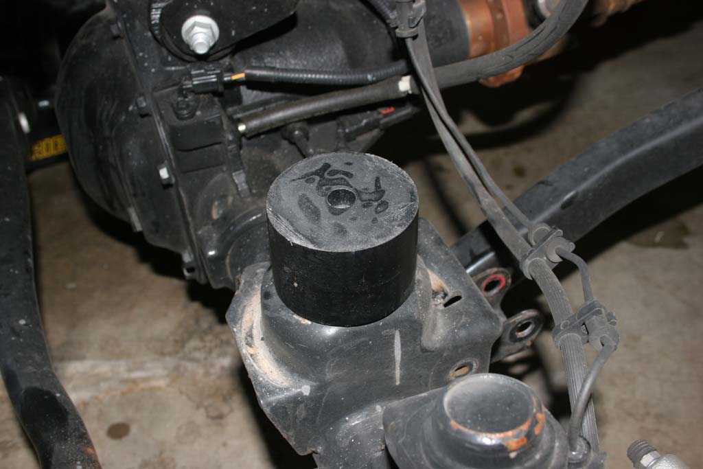
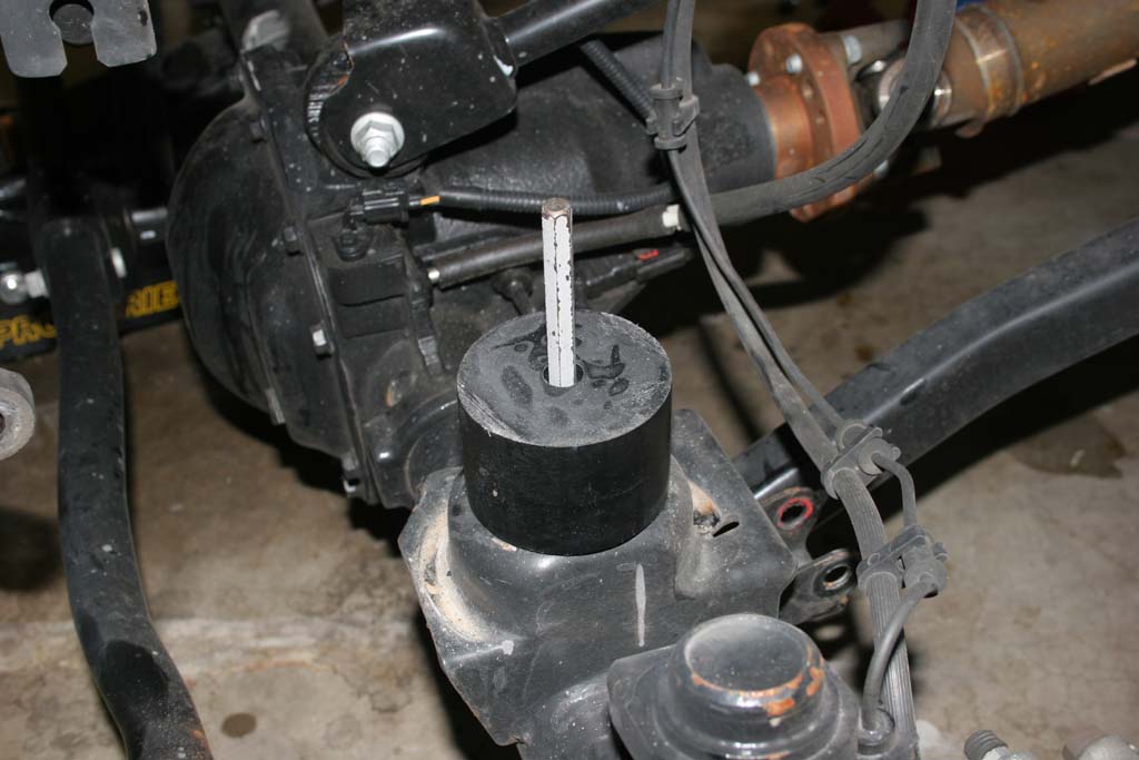
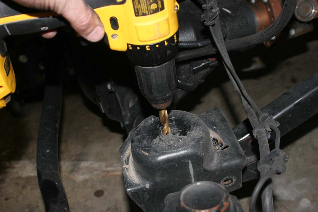
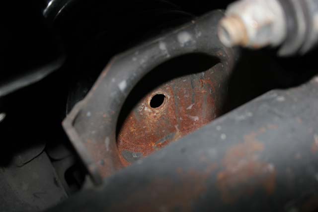
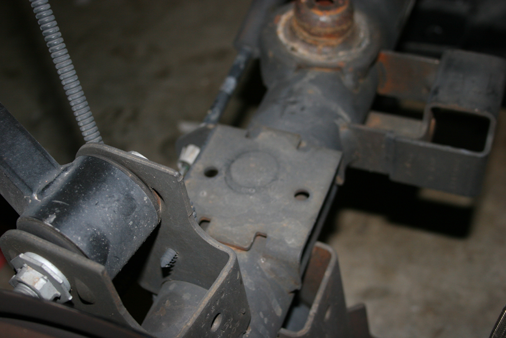
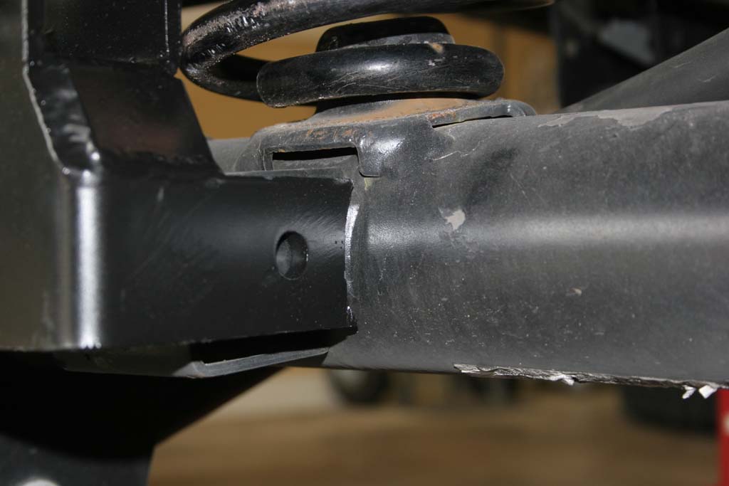
| 8. Drill a 3/8" hole centered in the front spring bad. This will be for the bump stops. Touch up the hole with some paint to prevent rusting. Alternately you can drill a 5/16" hole and tap it to 3/8"-16 with a tap. I tapped one side, and drilled the other, didn't see any difference long term. |
 |
 |
 |
 |
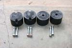
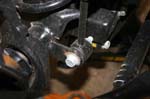
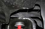
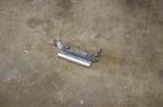
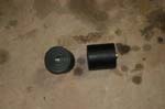
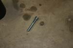
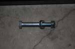
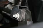
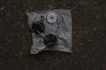
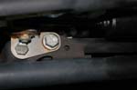
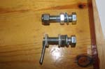
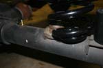
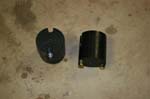
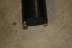
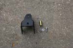
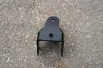
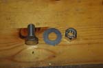
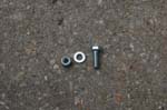
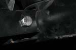
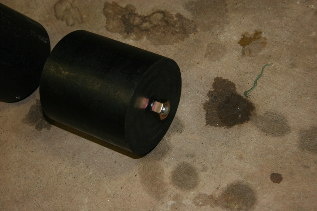
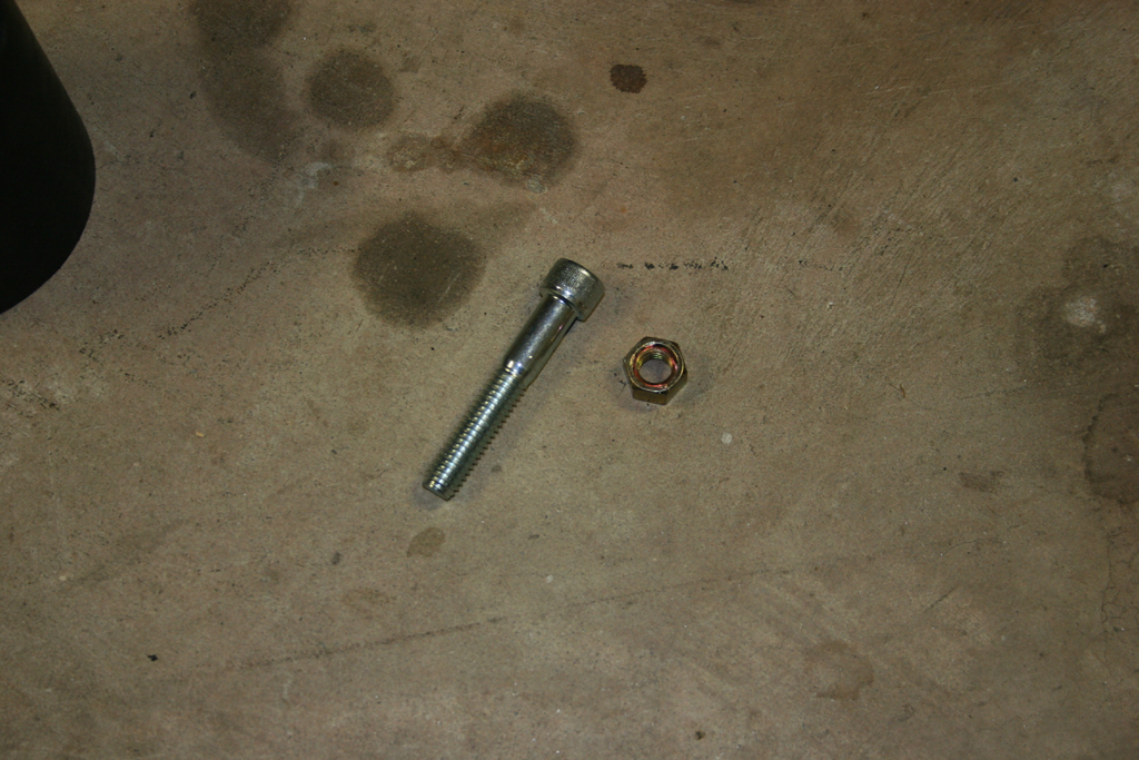
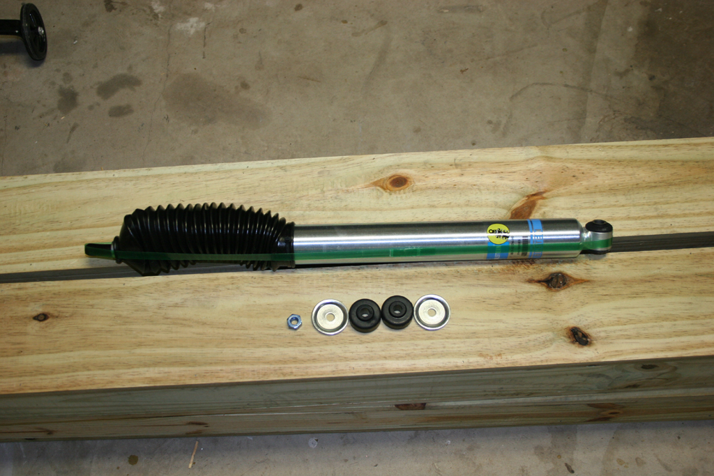
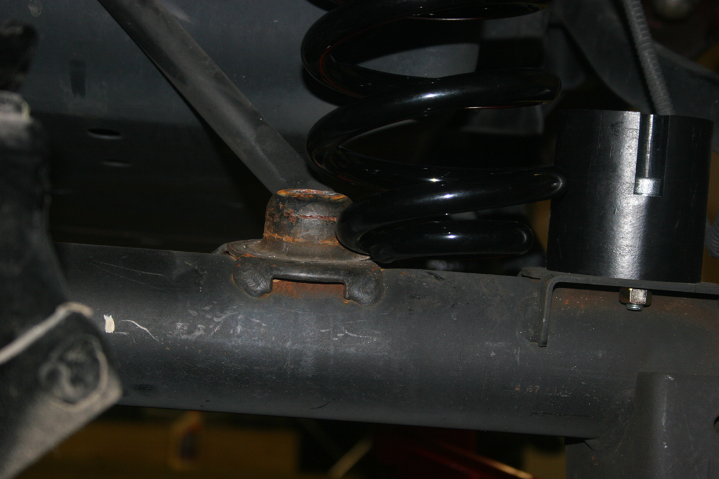
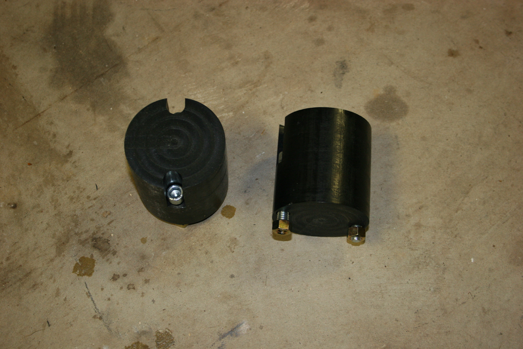
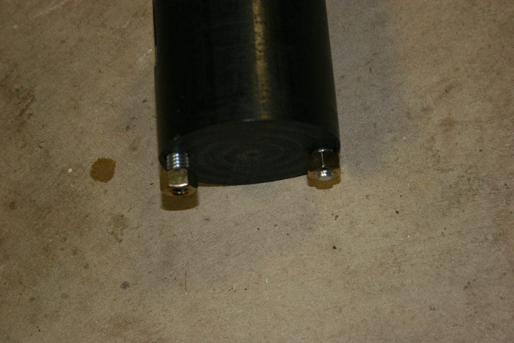
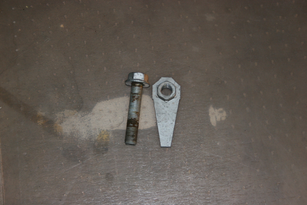
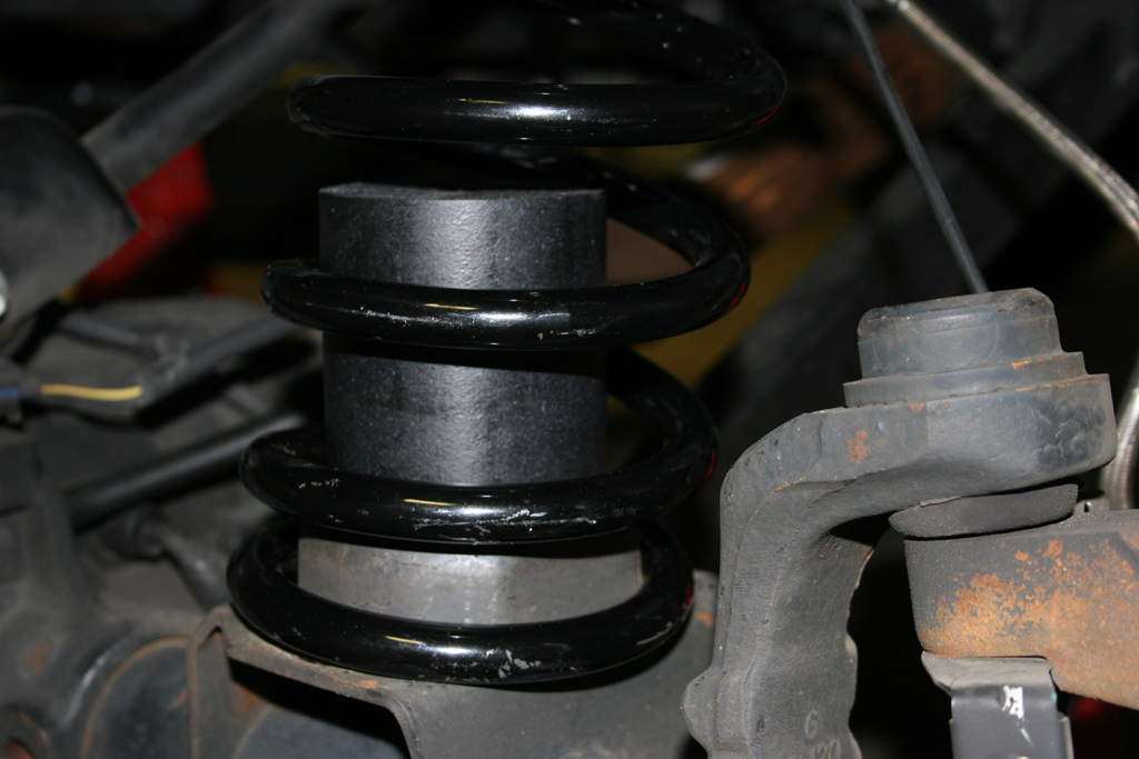
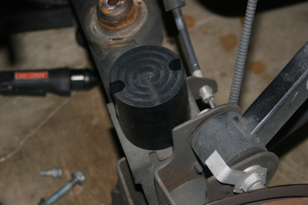
| 8a. This is what the bump stops with the screws look like. The nut will go up inside the spring pad from the bottom. |
 |
 |
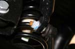
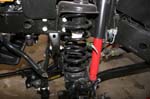
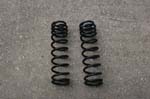
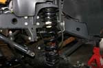
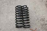
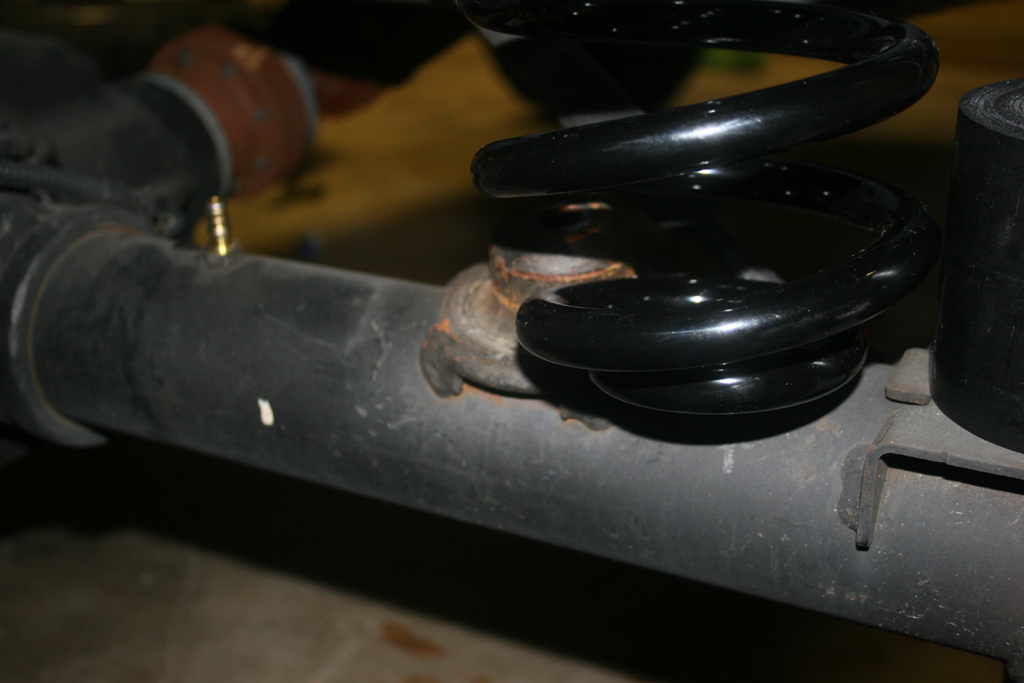
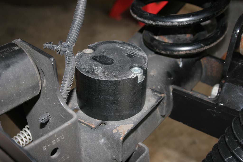
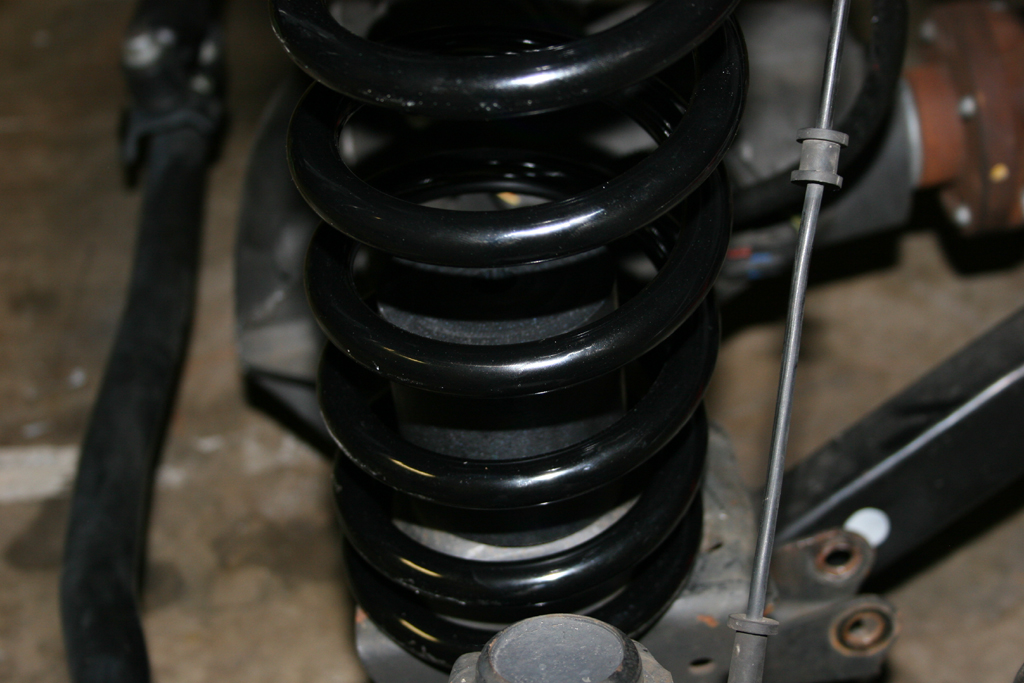
| When installing the front RockKrawler springs ensure that the close wound coil section goes up. |
 |
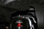
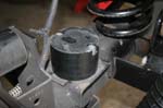
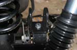
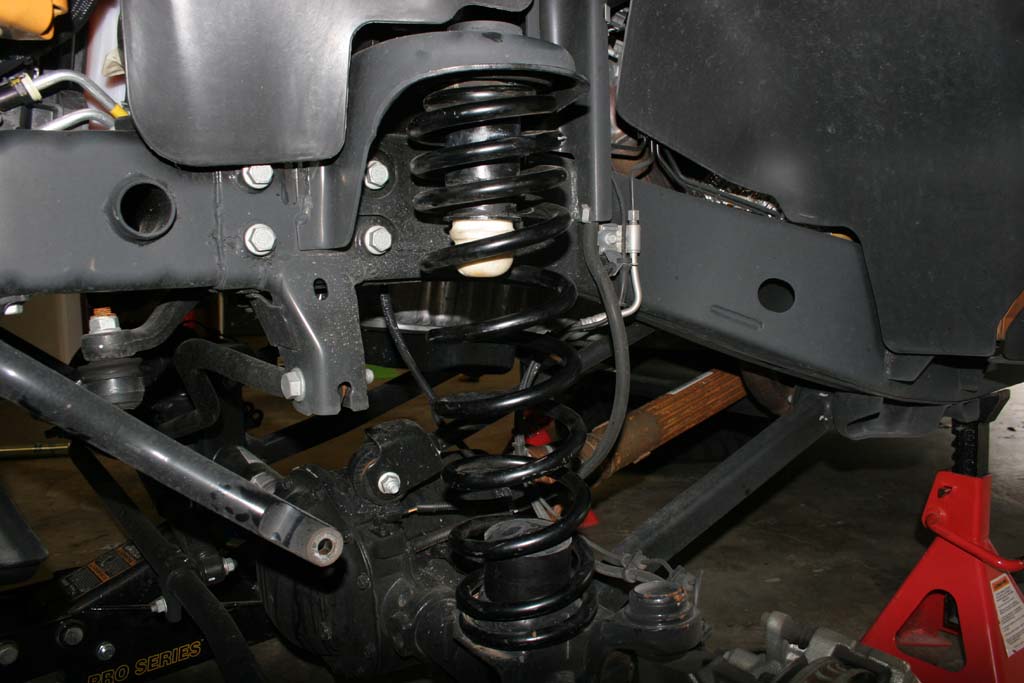
| 9. Lift the Rock Krawler spring up around the upper bump stop, slide the Clayton bump stop up into the spring (small hole down) and push the spring over the lower spring mount. A large flat screwdriver can help wedge the spring up and over. A few other ways are jacking up the opposite end of the axle, using a spring compressor, or a large friend standing on one end of the axle. |
 |
 |
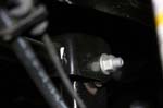
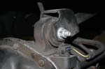
| 10. Insert the bolt through the bumpstop and into the spring pad. Thread the nut onto the bolt, and tighten down. You will need a 5/16 " allen wrench and a 9/16" combo wrench. |
 |
 |
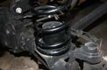
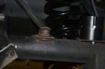
| 11. Make sure you index the spring into the notch on the spring pad. |
 |
12. Repeat the steps for the opposite side. You will need to jack up the side you just did to assist in getting the springs in on this side.
Note: Be careful you do not lift the Jeep off of the Jack stands and release the pressure to fast afterwards. |
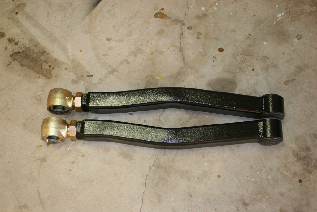
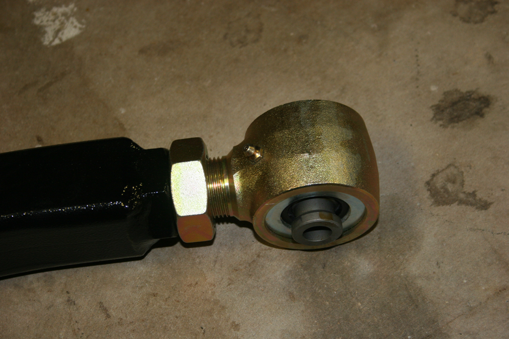
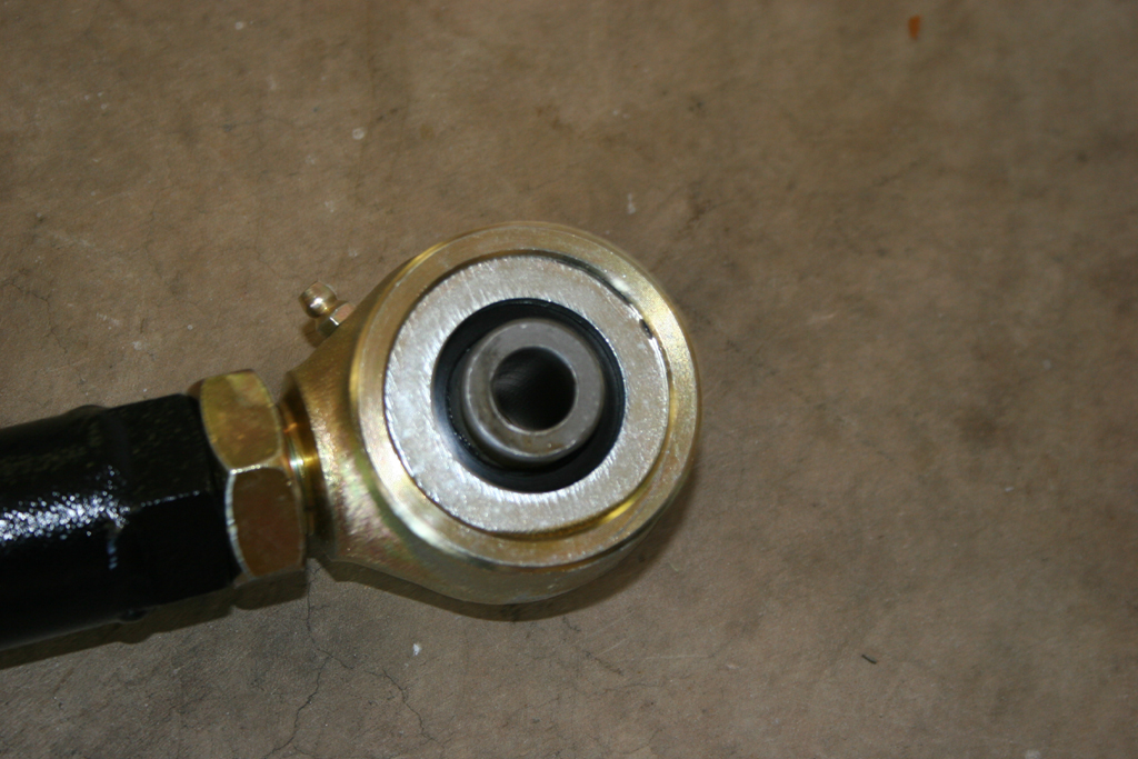
| 13. Find the lower control arms and install the zerk fittings.Do not overtighten the zerk fittings, you will snap them off. You will need a 5/16" combo wrench or socket. |
 |
 |
| 14. Adjust the lower control arms to 23 inches in length. Snug up the jam nut, we will tighten it once the arm is installed. |
 |
| 15. With the suspension lowered. Remove the lower control arms. You will need a 21mm Socket and 21mm Combo wrench |
 |
 |
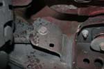
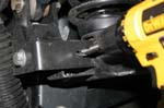
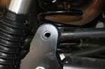
| 16. Grind out the lower control arm mount on the axle. You will need to do this to allow the square tubing of the clayton arm to articulate. You now have more suspension travel and without grinding out the bracket you will be limited by the control arm making contact. |
|
|
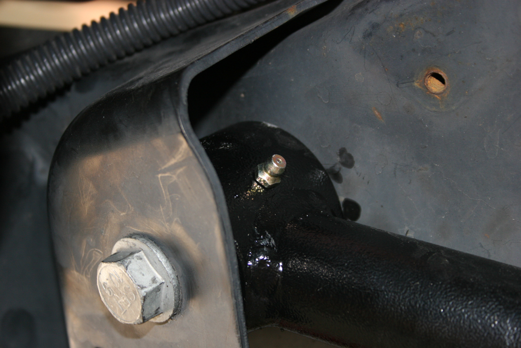
| 17. Install the Lower control arms. Reuse the factory hardware. Do not tighten yet, just snug up the bolts. The rubber bushing goes to the axle. Make sure the arm bends in for clearance when turning and that the grease fitting is pointed up to avoid it getting sheared off by a rock. |
|
|
| 18. Upper control arms. A new metric bolt is provided for the passenger side frame mount. You will be cutting this bolt off to remove the arm. It hits the exhaust manifold and can not be removed without moving the engine. Simpler to cut and replace it. This is for the 2007-2011 models. |
 |
 |
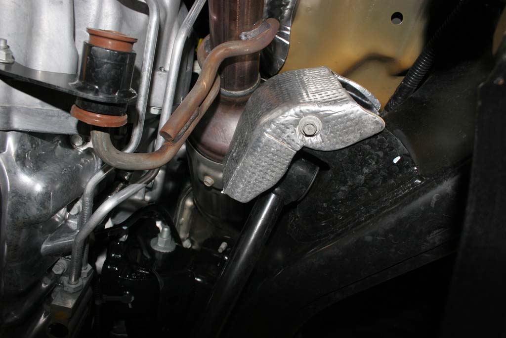
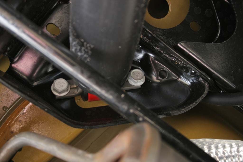
| 18a. On the 2012 and up models you can remove the passenger side bolt. You will need to remove the heat shields on both upper control arms. Remove the lower bolt with a 10mm socket and extension. I just removed the lower bolt and folded the heat shield up and out of the way. |
 |
| 19. Find the upper control arms and install the zerk fittings. Do not overtighten the zerk fittings, you will snap them off. You will need a 5/16" combo wrench or socket. |
 |
| 20. Adjust the Upper control arms to 18.75" in length. Snug up the jam nut, we will tighten it once the arm is installed. |
 |
 |
| 21. Support the pinion with a floor jack. You can use your scissors jack for you Jeep here. See, there is a use for that thing other than rusting in the back cubby hole. |
|
|
| 22. Remove the upper control arms. You will need to cut the passenger side frame side bolt to remove it. Be careful with the driverside bolt at the axle. On the Rubicon models the electrical connectors for the lockers are near the bolt, and the cables connect to the control arm. You will need to disconnect the cable from the control arm. You will need a |
 |
 |
 |
 |
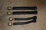
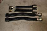
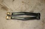
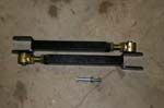
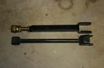
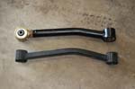
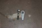
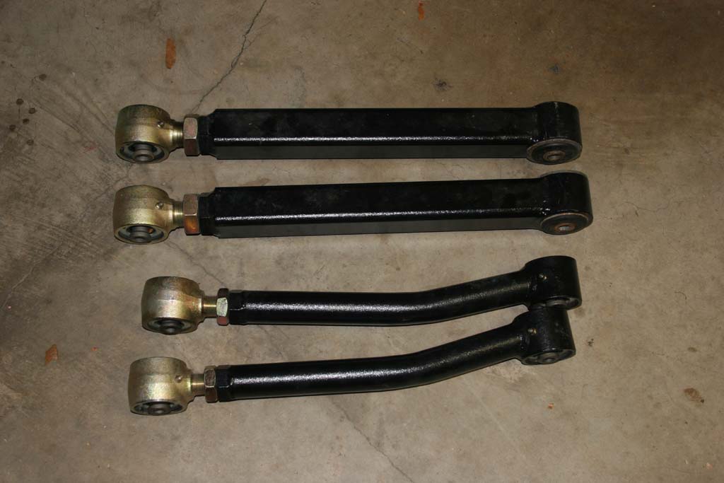
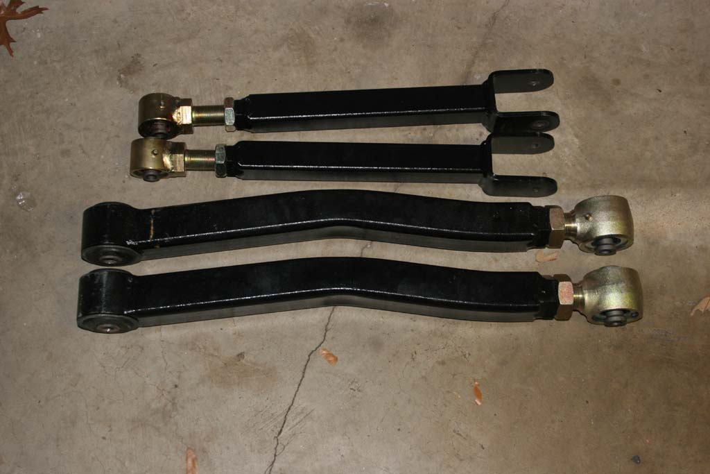
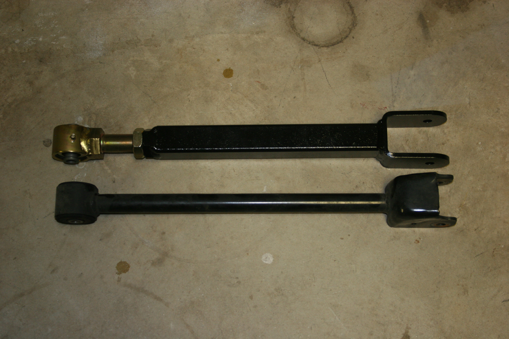
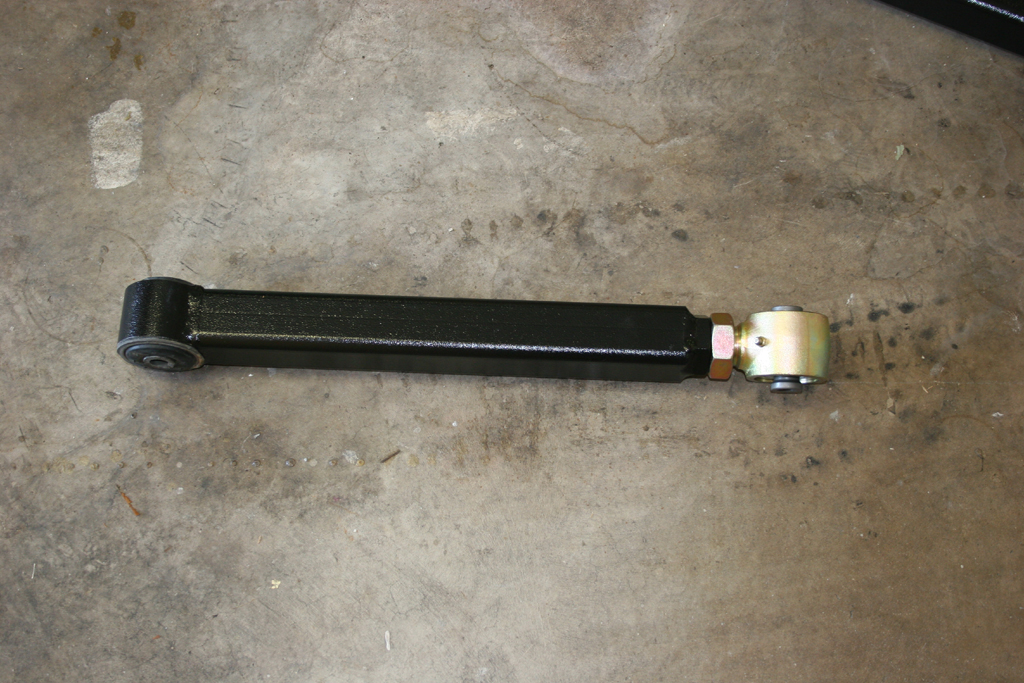
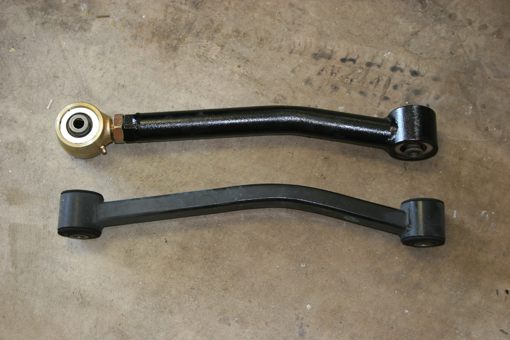
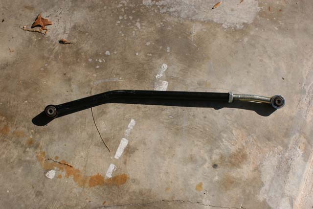
| 22a. Quick comparison shot of the Clayton arm compared to the stock arm. The stock arm is fairly beefy compared to the older TJ arms, but still pales in comparison to Claytons arm. |
 |
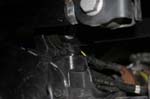
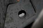
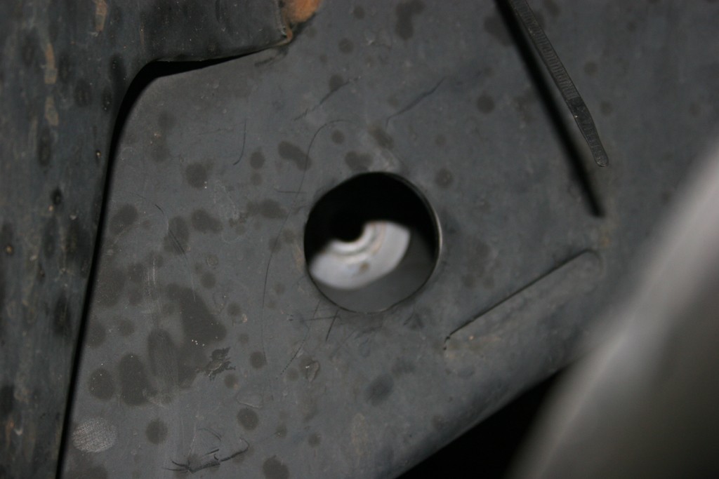
| 23. The BLACK HOLE! The fun part of installing the new upper control arms is the passenger side frame mount. You will need to slide the new provided bolt through the frame, into the arm and then out the other side of the mount before you can put a nut on it. This is made more difficult by the tiny hole you have to slide it through. I dropped it twice before I got it lined up and through. Fishing the bolt out of the frame is a fun adventure. Of course the bolt is the easy part to get out, the washer also goes down with it... |
 |
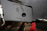
| 23a. The BLACK HOLE 2. The same hole is on the 2012's and up, but this time it will swallow the nut for the bolt. Yes, I managed to lose the nut down inside the hole even with it having a flange on it. The hole on the opposite side of the frame is large enough for it to slide in. |
 |
| 24. Bolt in the new upper control arms. You can use the jack under the pinion to rotate the axle to line up the axle side bolt holes. Be careful with the driverside bolt at the axle. On the Rubicon models the electrical connectors for the lockers are near the bolt. You can install these arms with the grease fitting facing down. |
|
|
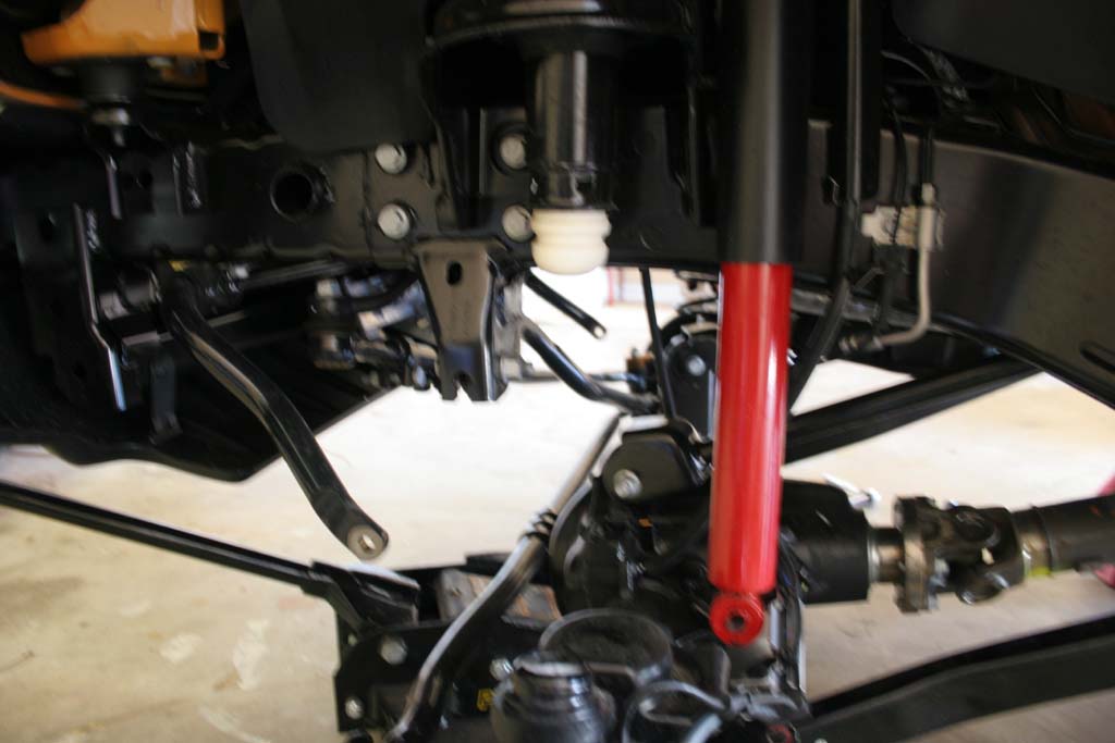
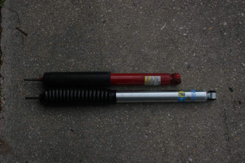
| Front Shocks: |
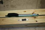
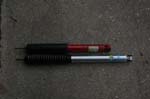
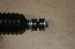
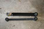
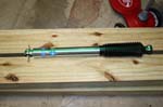
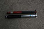
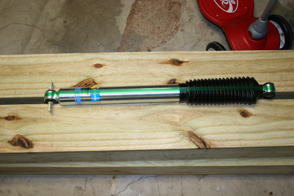
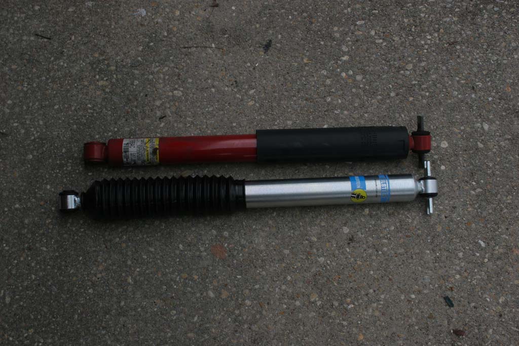
| The new front shocks and a comparison. |
 |
 |
 |
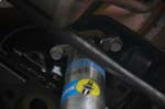
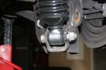
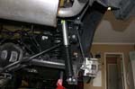
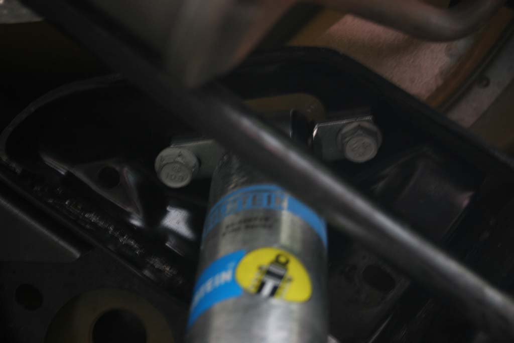
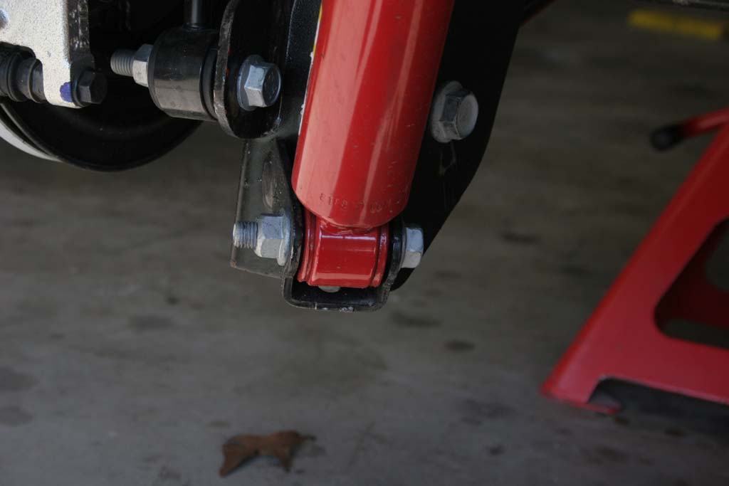
| 25. Install the new front shocks. |
 |
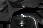 |
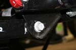
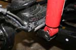
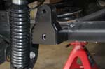
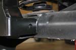
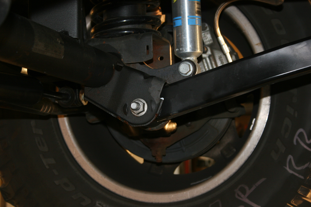
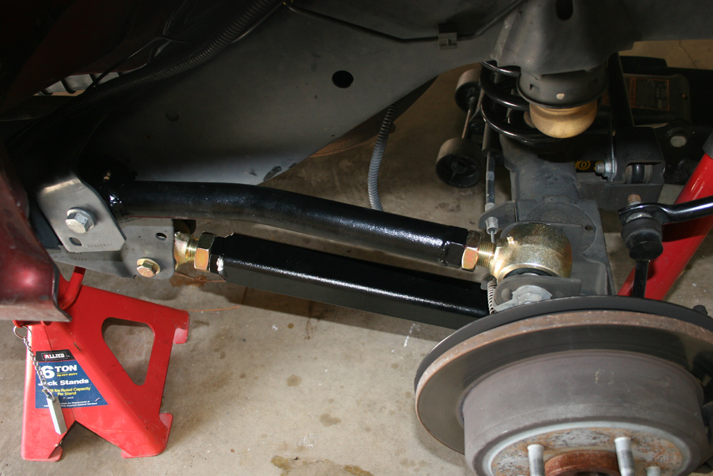
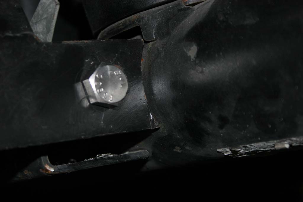
| 25a. The lower bolt needs to be installed from the inside to allow for clearance of the lower control arm. The nut should be closest to the tire. |
 |
| Front Adjustable Track Bar: |
| 26. Reinstall the front tires and take the front end down off the Jack stands this next part is much easier to do with it on the ground. |
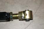
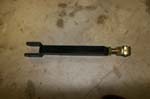
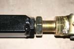
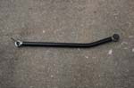
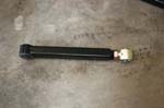
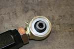
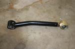
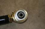
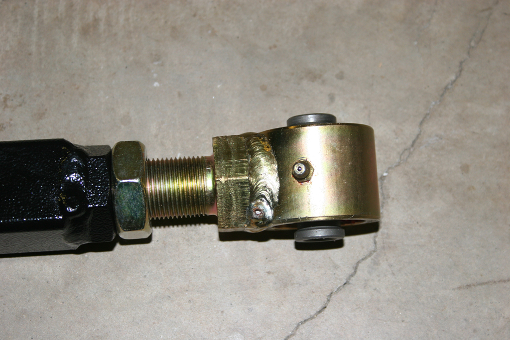
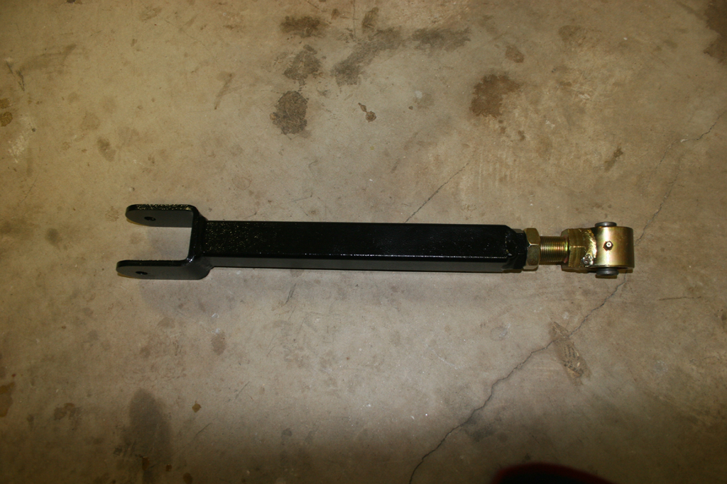
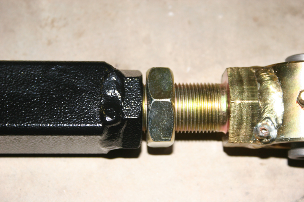
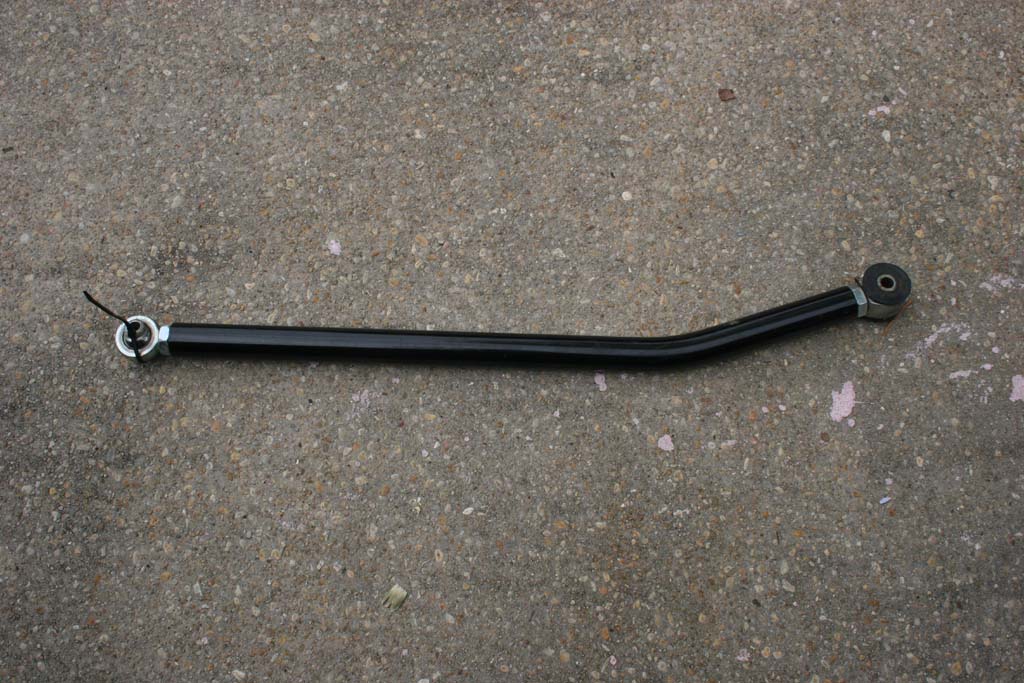
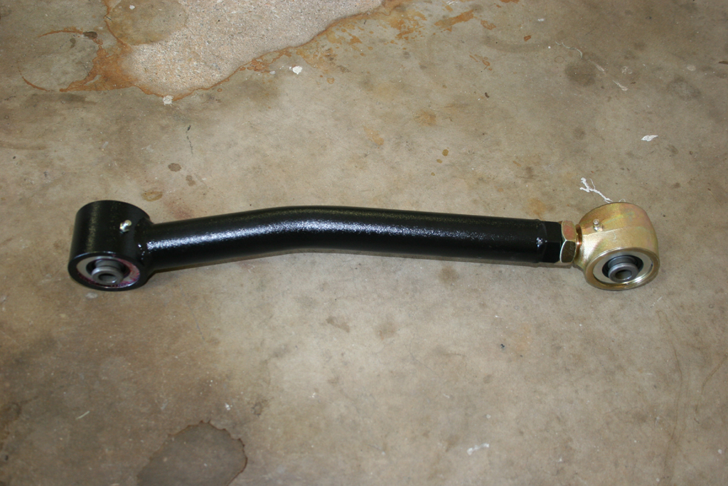
| 27. Install the front adjustable Trackbar. Adjust the trackbar to 32 7/8" center to center. The Bushing goes on the axle side, and the heim joint goes on the frame size. Do not tighten up the bolts. |
| The RockKrawler bar comes complete by itself, no extra parts needed, you will reuse your stock bolts and nuts. |
 |
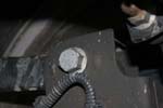
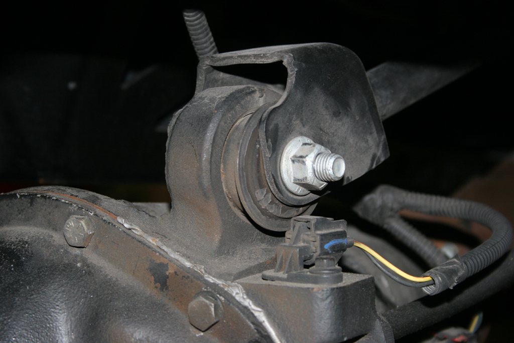
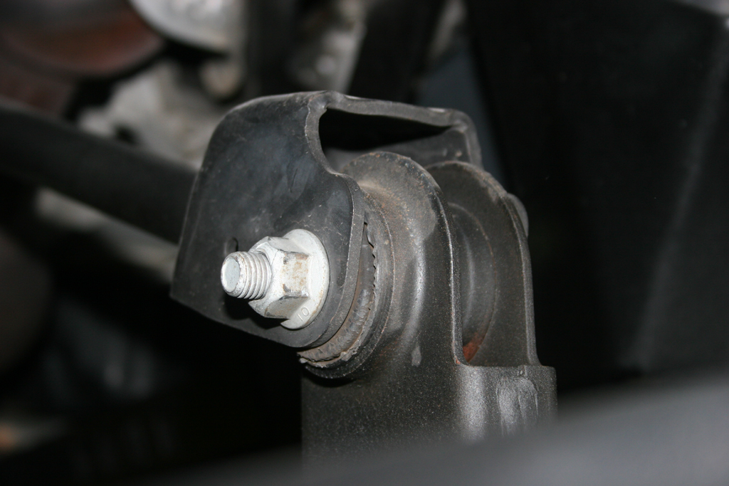
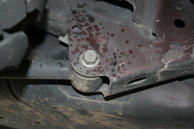
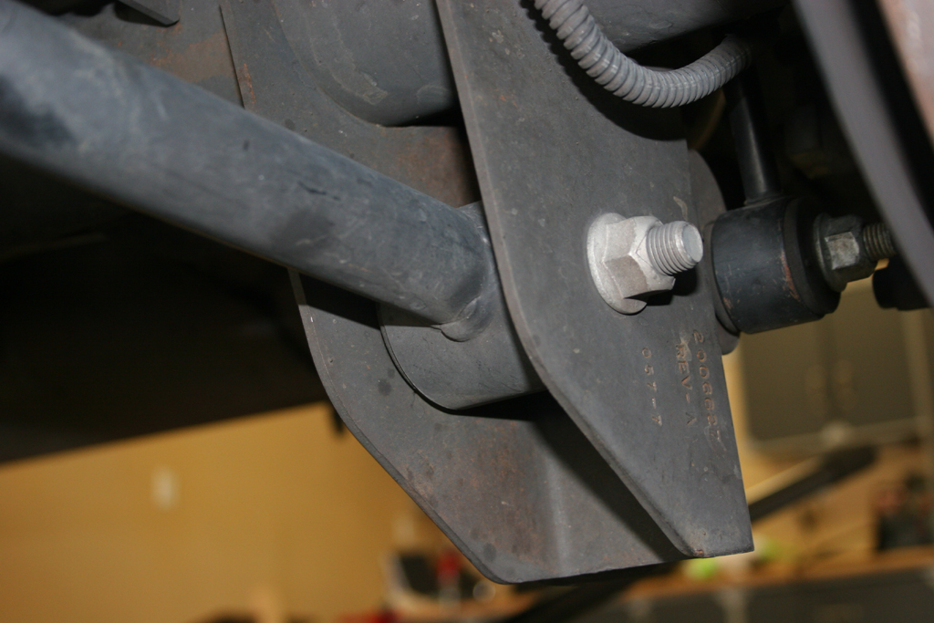
| 28. Remove the stock track bar bolt from the frame with a 21mm socket and combo wrench. This is really tight, so be careful with your hands. |
 |
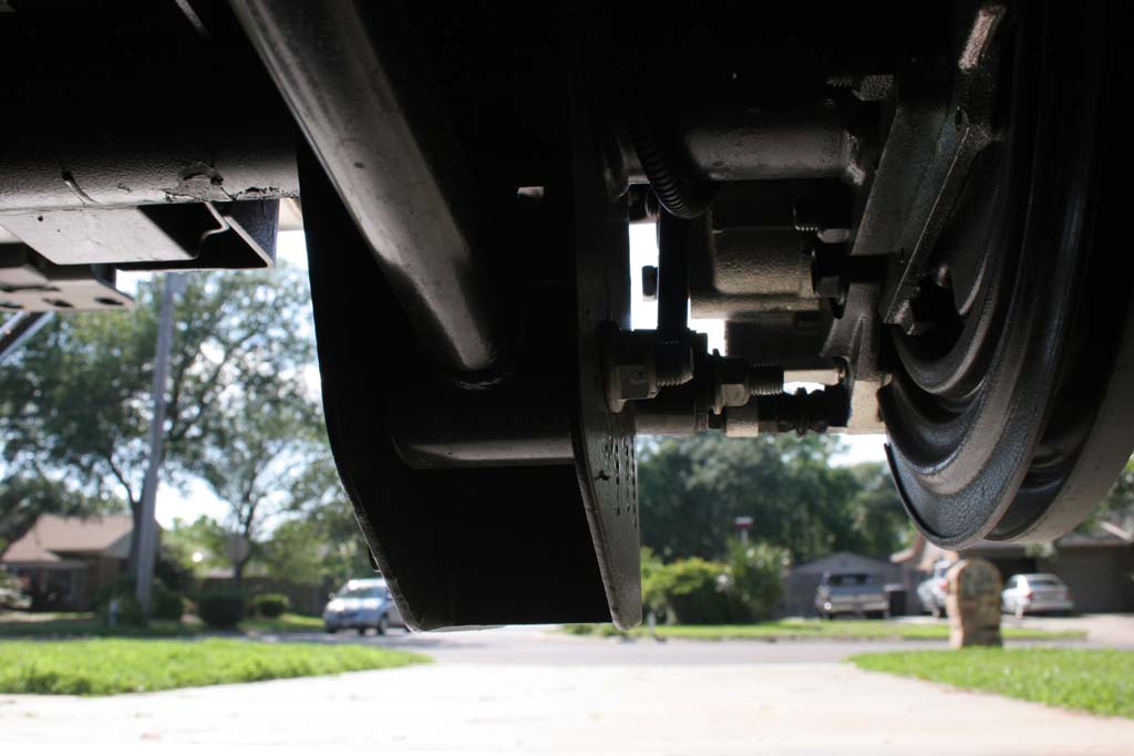
| 29. Remove the stock track bar bolt from the axle with a 17mm socket. There is a blind nut on the back side that will fall out once you remove the bolt. Remove the stock trackbar. |
 |
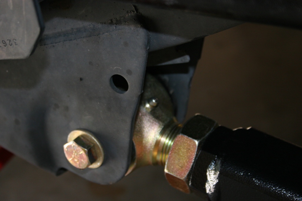
| 30. Install the frame side of the RockKrawler track bar into the axle bracket on the Jeep. Do not torque this bolt down yet. |
 |
| 31. Now measure to see where your front axle is sitting in relation ship to the frame. Take the difference between the measurements and divide by two, this is how far over you will need to move the axle. My axle was 3/4" over on the drivers side so I needed to move mine over 3/8". |
|
|
32. Now adjust the RockKrawler track bar out until you have the about the correct length that you need to adjust the axle over. I needed to move mine over 3/8", so I just extended the trackbar until the hole in the trackbar was 3/8" further than the hole in the axle bracket. |
|
33. Install the bolt in the axle bracket for the trackbar. Here is where a friend or really strong legs come in handy. Believe me friend is easier. My 5 year old helped me with this one.Turning the steering wheel will cause the body and frame on the Jeep to move over, doesn't take a lot to get the holes to line up.
NOTE: I do not suggest Starting the Jeep, just unlock the steering wheel and do it manually. Something about laying underneath a running vehicle. Watch where your hands are in relationship to all moving parts, and maintain a good communication with your assistant. You can alternately use (I don't recommend) a ratchet strap to move the frame, but don't use one of the cheap little straps, they are generally only rated for 200lbs and can snap under tension, and you will be right in line with the hooks and ratchet. |
 |
| 34. Torque the trackbar axle bolt and the trackbar frame bolt. Make sure you get these torqued properly. Loose bolts on the trackbar is a leading cause of Death Wobble. |
|
|
| NOTE: After you take it for a drive, recheck the axle to frame position measurements. You may need to make a second adjustment. Recheck the torque on the axle and frame bolts. |
| Front Anti-Swaybar Links: |
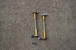
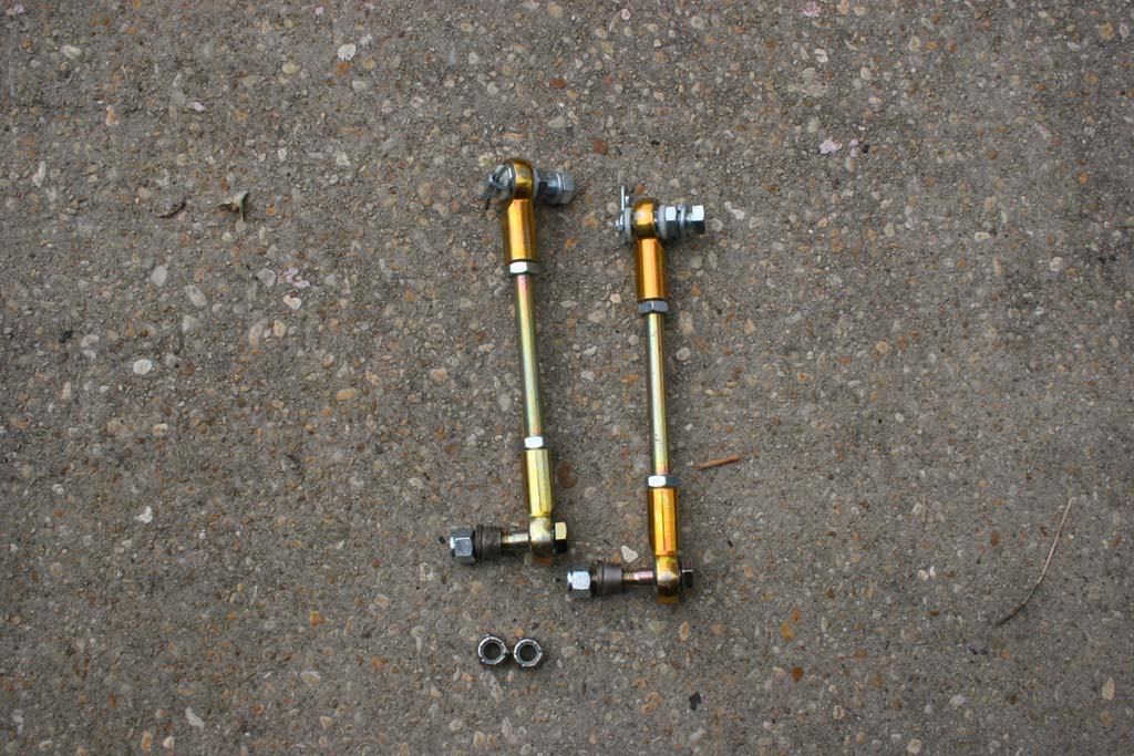
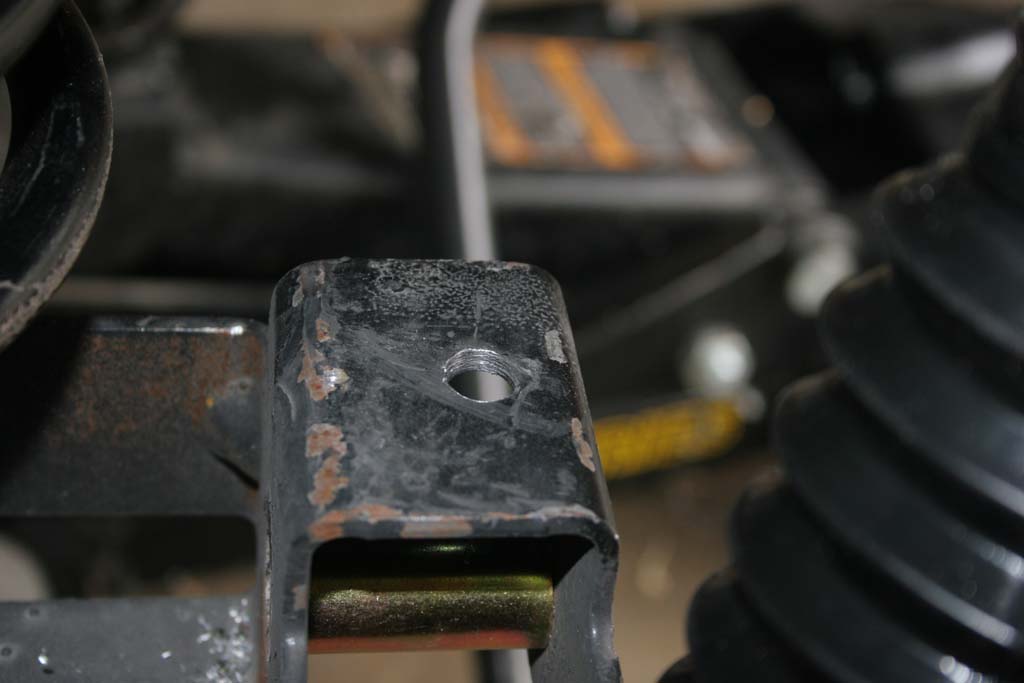
35. Install the front sway bar disconnects.
Note: On some sway bars you may have to reem out the hole to ½” with a ½” drill bit. I used a stepped drill bit to keep it centered, it's difficult drilling it with a 1/2" drill bit. |
 |
 |
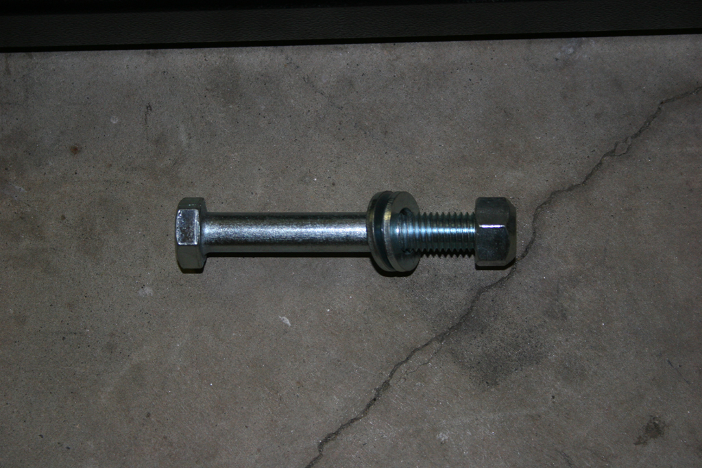
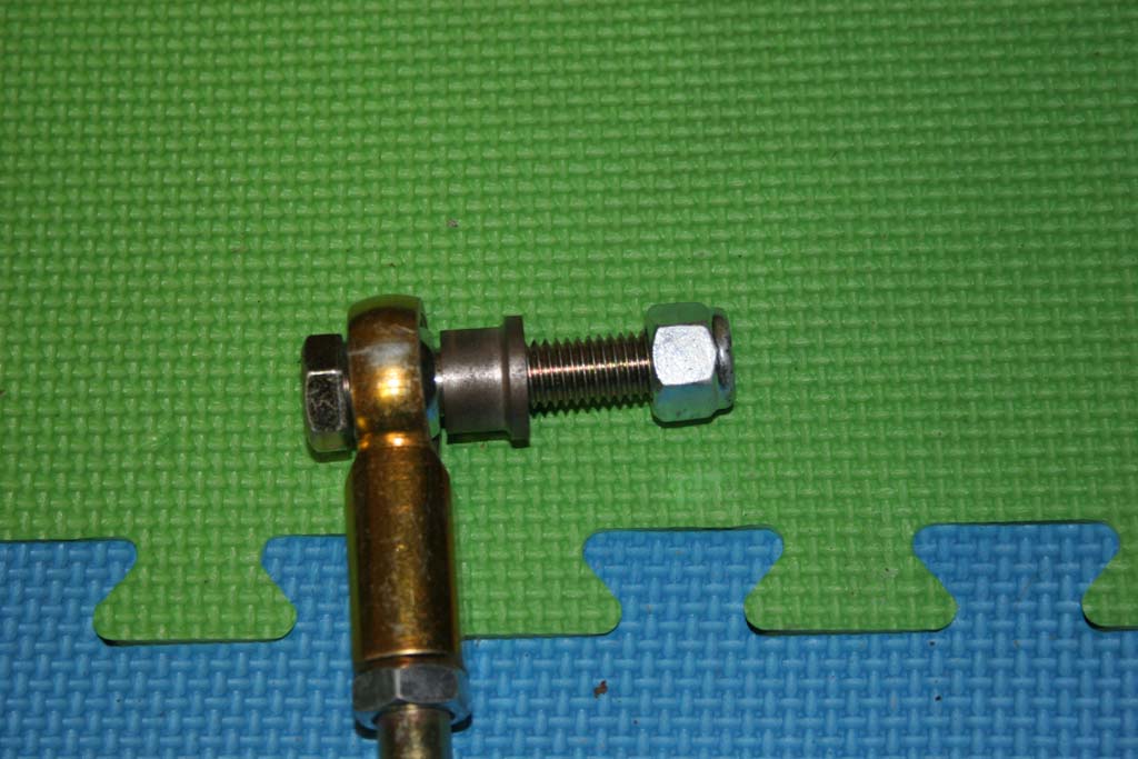
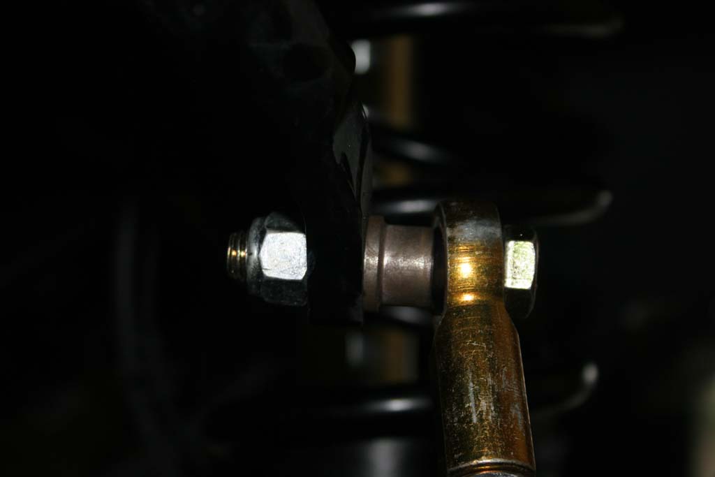
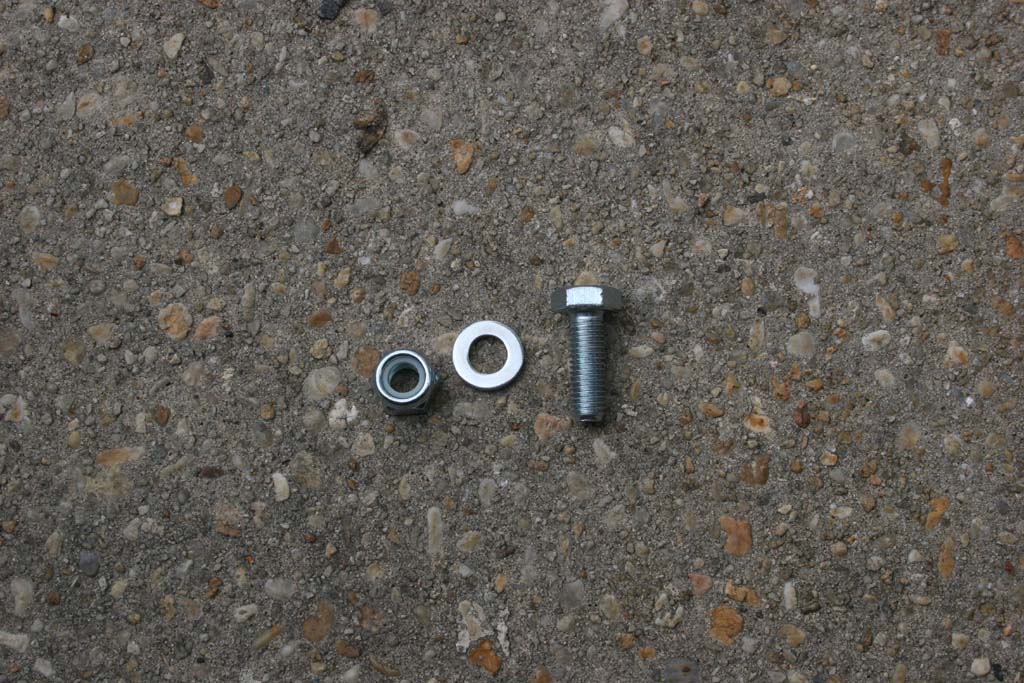
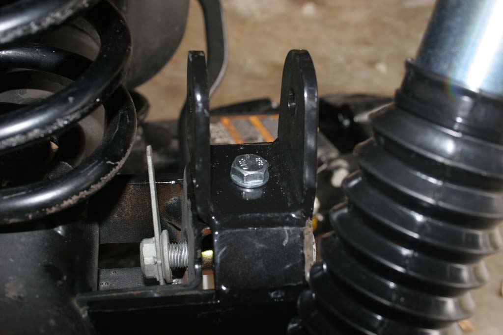
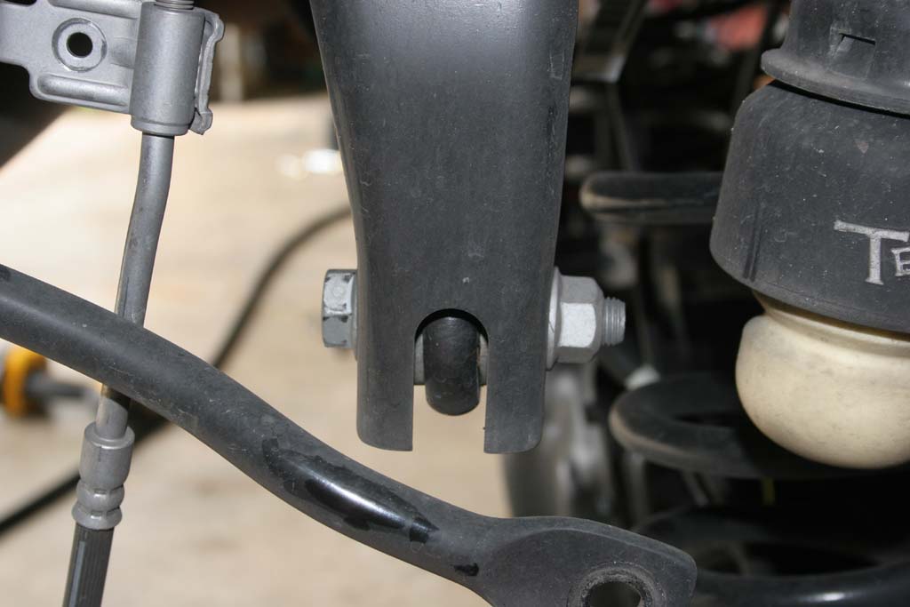
36. For the top mount use the supplied ½” x 2.5” bolt, .595” long spacer, and nylok nut to make the connection.
Note: The shoulder of the spacer goes against the sway bar itself. |

|
 |
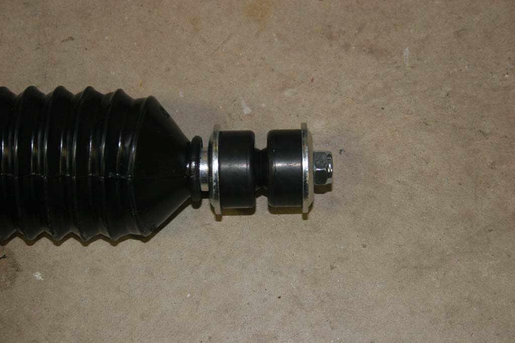
| For connecting the bottom end of the sway bar link to the bottom bolt there are two options supplied with each kit. If you do not have the automatic sway bar disconnect feature you can secure the bottom end of the sway bar link with the 2 nylon washers on either side of the rod end and secure it with the pin. If you do have the automatic sway bar disconnect feature you can simply secure the bottom rod end with the supplied ½” nylok nut. |
 |
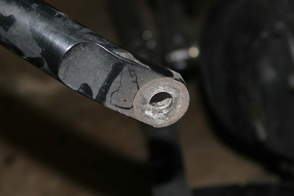
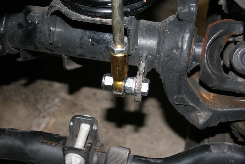
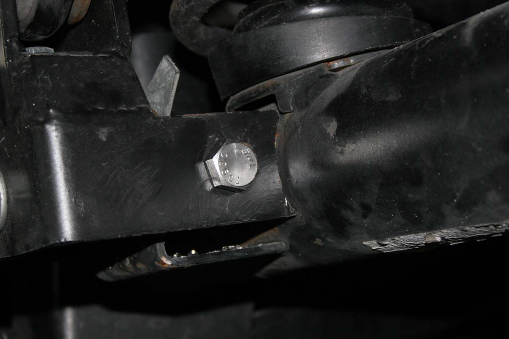
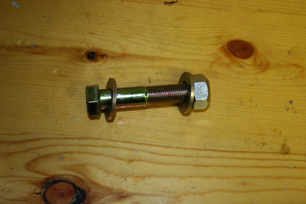
| 37. For the bottom connection attach the ½” x 2.0” long bolt with cross drilled hole to the factory sway bar link bracket. Secure the bolt with the supplied ½” jam nut. |
 |
| 38. You will need to adjust your lenght's so that the sway bar sits approximately parallel to the ground when the weight is on the suspension. On the Rubicon models you may want to have your front anti-sway bar pointed up slightly. The flex on the stock mod may allow the front anti-sway bar to invert itself and mangle your sway bar links. |
 |
| 39. Jack up the front suspension and install the tires. |
| |
| Rear Suspension Installation: |
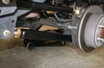
| 1. Jack up the rear suspension and support the Jeep with Jack Stands in front of the lower control arm. Remove the tires. Leave the floor jack under the axle to relieve some pressure on the bolts for the next couple of steps. |
| 2. Loosen the following bolts: Upper control arms and lower control arms. You will need a 18mm and 21mm socket and combo wrench. |
 |
 |
 |
 |
| 3. Remove the following bolts/nuts: |
Lower shock bolts, upper shock bolts. You will need a 18mm socket and combo wrench for the lower and a 16mm socket and long extension for the top.
|
 |
 |
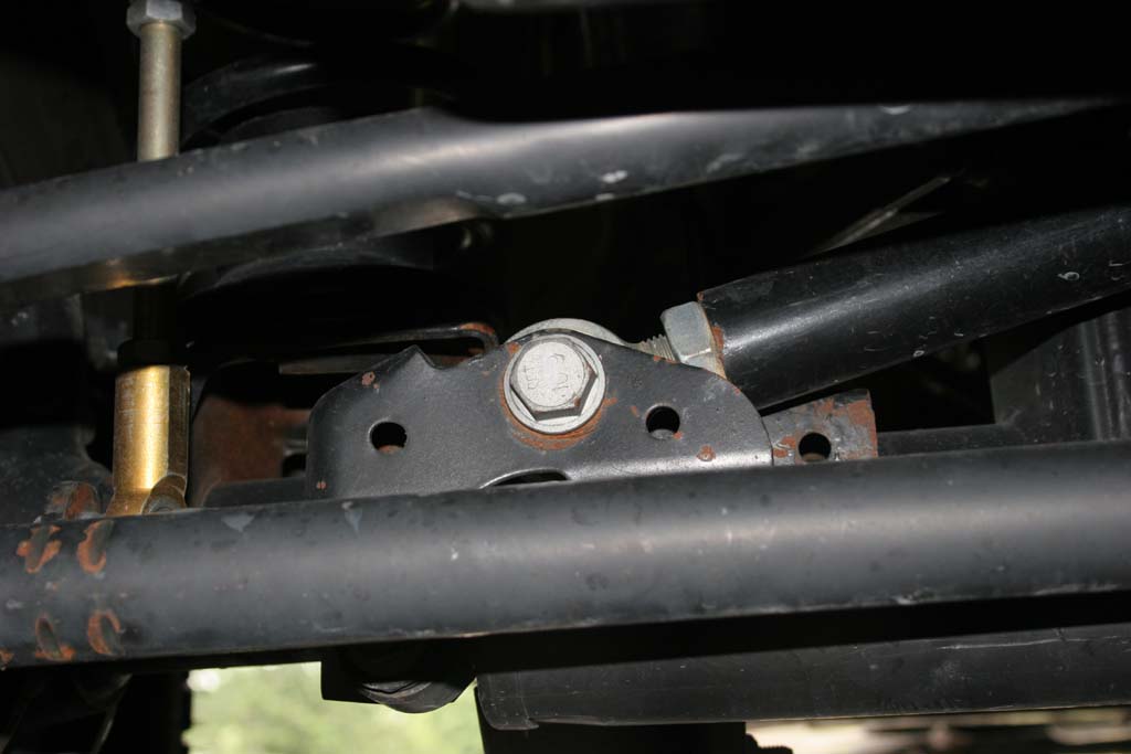
Rear anti-sway bar lower bolt. You will need a 18mm socket and combo wrench.
|
 |
 |
Rear trackbar lower bolt, rear trackbar lower bolt. You will need a 21mm socket and combo wrench.
|
 |
 |
Brake line mount to frame. You will need a 10mm socket.
|
 |
 |
Emergency Brake bracket. You will need a 10mm deep well socket. I left the cables free of the bracket, though I did bolt the bracket back into place to avoid loosing it. |
 |
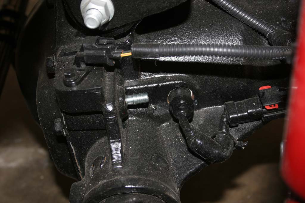
| 4. Unclip the speed sensor cables from the frame for each wheel hub. You will need the extra slack. |
 |
 |
| 4a. For Rubicon models, you may need to unclip the rear locker cable to the differential. |
 |
 |
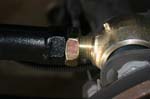
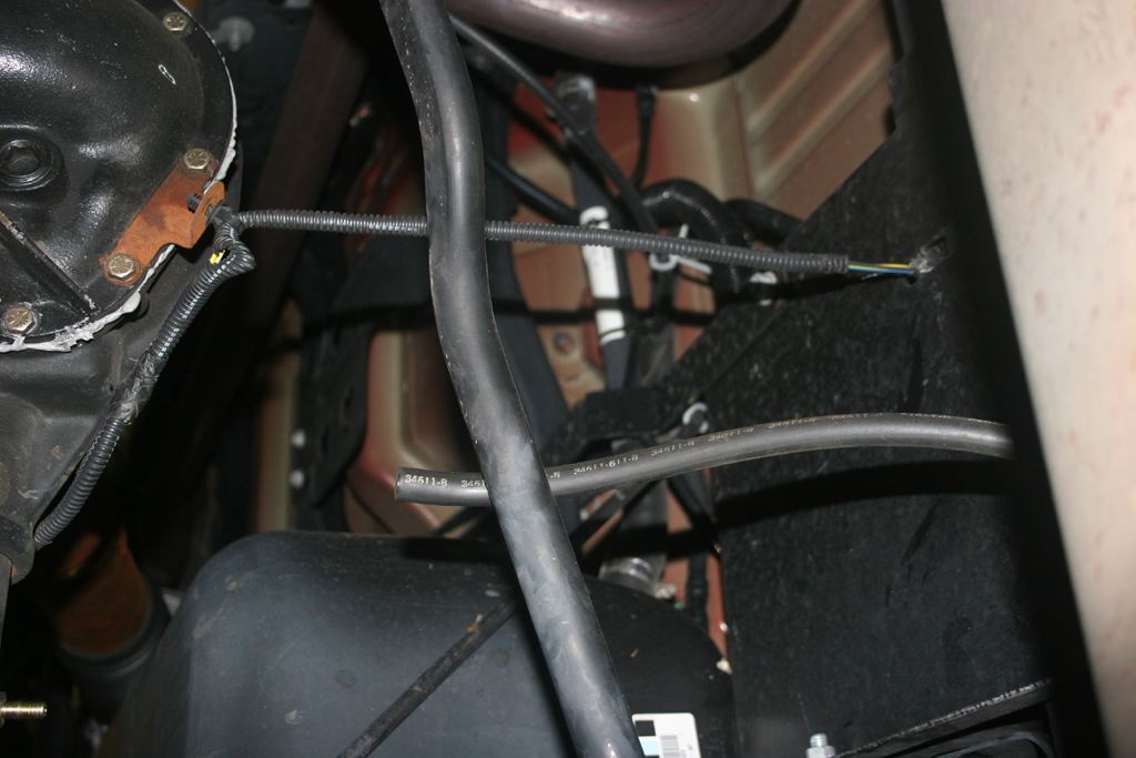
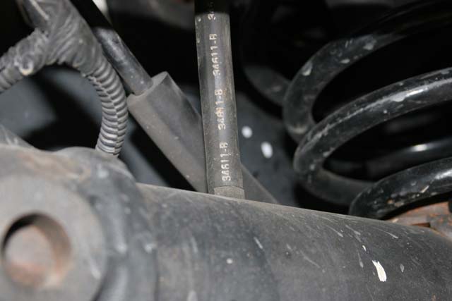
| 5. Slowly twist and work the rear differential breather line off of the fitting on the axle. |
 |
 |
| 6. Slowly lower the axle down towards the ground. Watch the brake lines, speed sensor lines and the locker cable on the differential. |
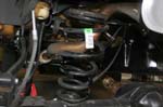
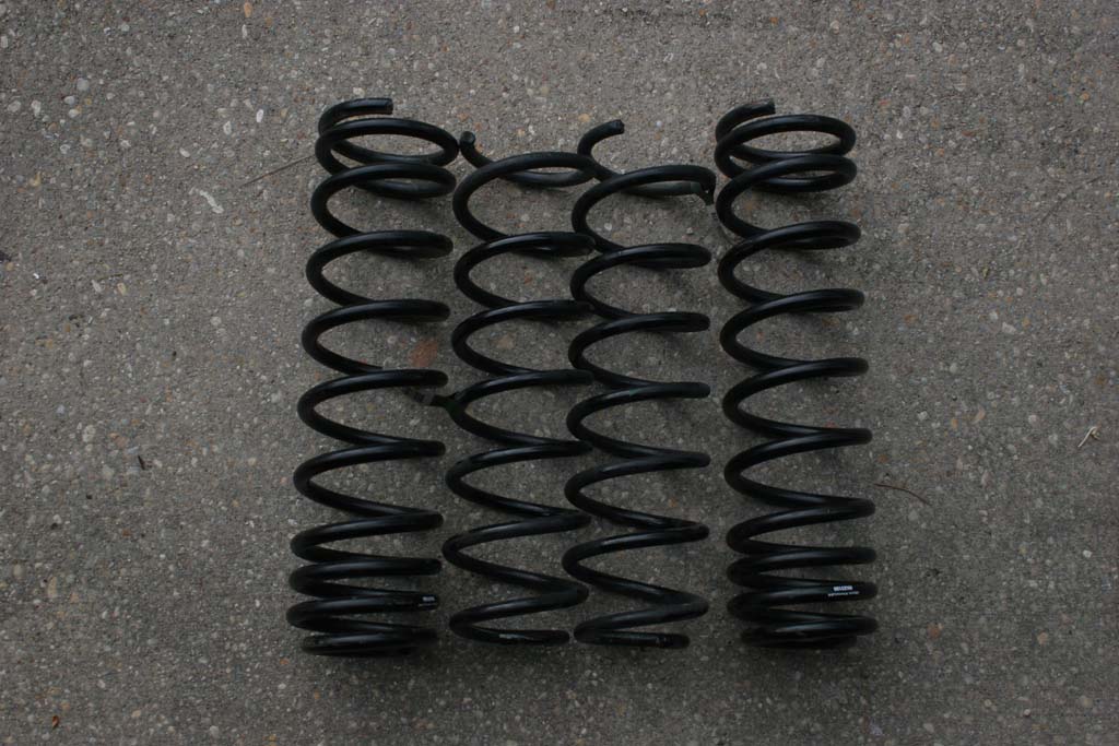
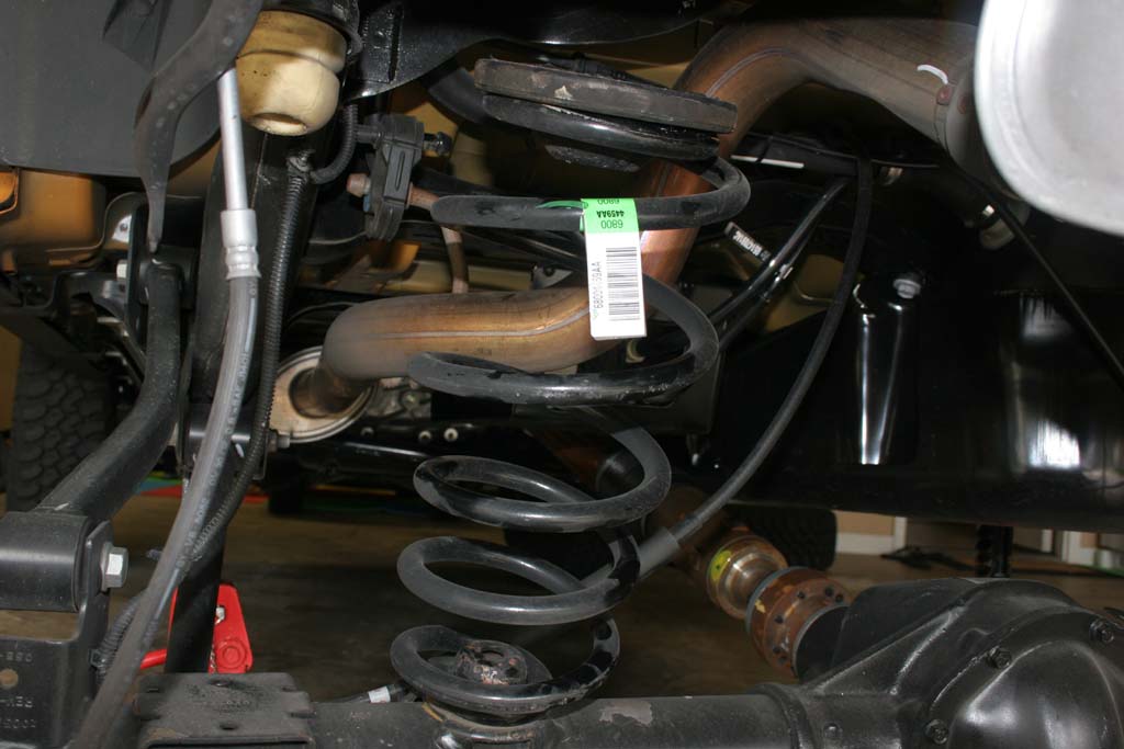
| 7. Remove your rear springs. They should just pull right out. |
 |
 |
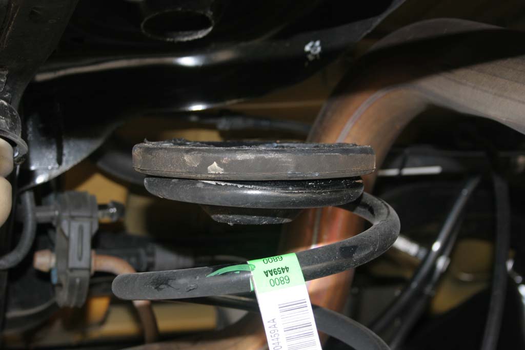
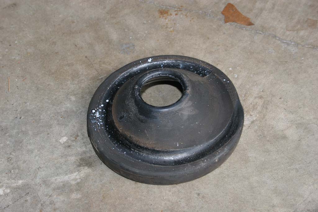
| 8. Remove the upper spring isolator, or chase it down the driveway after it falls off. Place it on top of the RockKrawler springs. The tighter wound side of the spring goes down. |
 |
 |
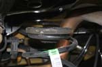
| 8a. Quick comparison shot |
 |
 |
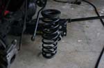
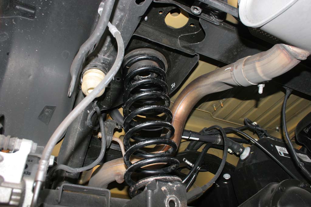
| 9. Lift the Rock Krawler spring up around the upper bump stop (small hole down) and push the spring over the lower spring mount. A large flat screwdriver can help wedge the spring up and over. A few other ways are jacking up the opposite end of the axle, using a spring compressor, or a large friend standing on one end of the axle. |
 |
 |
 |
10. Repeat the steps for the opposite side. You will need to jack up the side you just did to assist in getting the springs in on this side.
Note: Be careful you do not lift the Jeep off of the Jack stands and release the pressure to fast afterwards. |
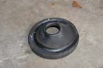
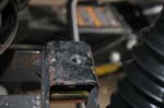
| 11. This is what the bump stops with the screws look like. The nut gets screwed onto the bolts from below the pad on the axle. |
 |
 |
12. Install the bumpstop on the pad and tighten up the two bolts. You will need a 5/16 " allen wrench and a 9/16 " combo wrench.
Note: You may have issues with a bump stop over 2" here. The bolt for the upper control arm will not be removeable without removing the bump stop first. |
 |
 |
| 13. Find the lower control arms and install the zerk fittings.Do not overtighten the zerk fittings, you will snap them off. You will need a 5/16" combo wrench or socket. |
 |
 |
| 14. Adjust the lower control arms to 20" in length. Snug up the jam nut, we will tighten it once the arm is installed. |
|
| 15. With the suspension lowered. Remove the lower control arms. You will need a 21mm socket and combo wrench. |
 |
 |
 |
| 16. Install the Lower control arms. The lower control arm bushing goes on the axle side. You will need a 21mm socket and combo wrench. |
 |
 |
| 17. Find the upper control arms and install the zerk fittings.Do not overtighten the zerk fittings, you will snap them off. You will need a 5/16" combo wrench or socket. |
 |
 |
| 18. Adjust the Upper control arms to 3/8 inch longer than stock length. Snug up the jam nut, we will tighten it once the arm is installed. |
|
|
| 19. Support the pinion with a floor jack. You can use your scissors jack for you Jeep here. See there is a use for that thing other than rusting in the back cubby hole. |
|
|
| 20. Remove the upper control arms. You will need a 18mm socket and combo wrench. |
 |
 |
| 20a. Quick comparison shot of the Clayton arm compared to the stock arm. The stock arm is fairly beefy compared to the older TJ arms, but still pales in comparison to Claytons arm. |
 |
 |
| 21. Bolt in the new upper control arms, the bushing goes on the frame side. You can use the jack under the pinion to rotate the axle to line up the axle side bolt holes. Be careful with the driverside bolt at the axle. On the Rubicon models the electrical connectors for the lockers are near the bolt. You will need a 18mm socket and combo wrench. |
 |
 |
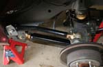
| 21a. Both arms installed. |
 |
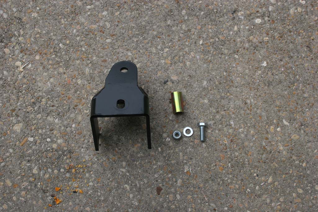
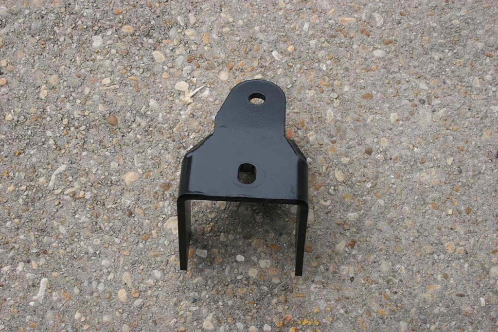
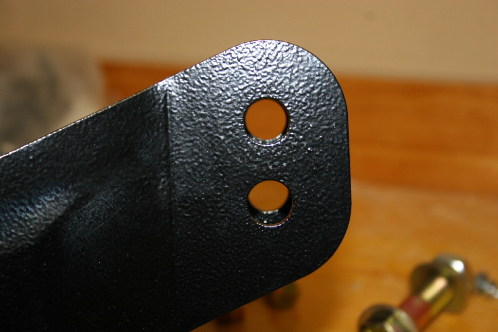
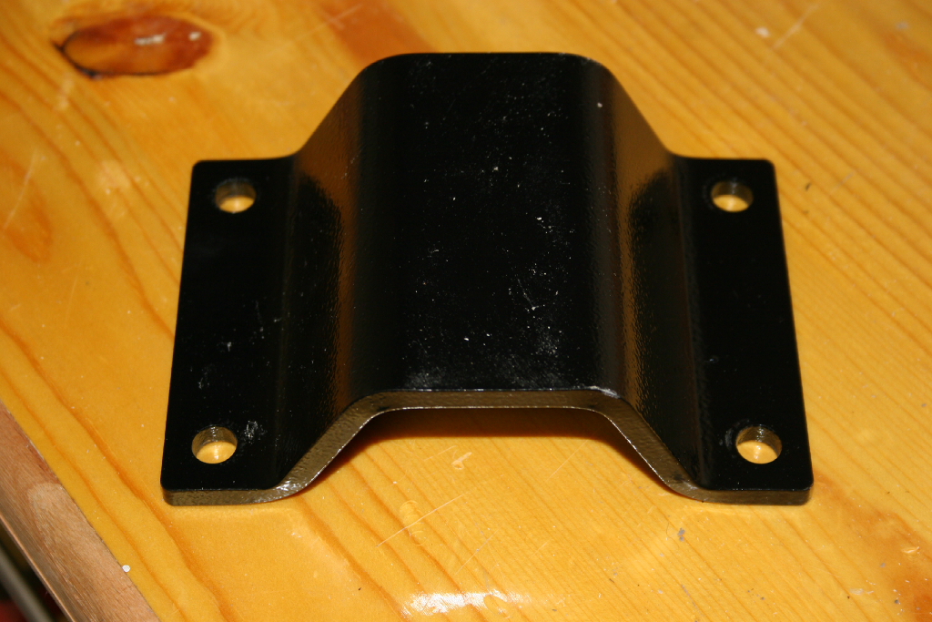
| Rear Trackbar Bracket Installation: |
| `This is the same trackbar bracket used on the 2.5", 3.5" and 4.5" RockKrawler lifts. It sits in about the right position for the 3.5" kit. The 4.5" will need the adjustable rear trackbar to get the axle centered. Unfortunately with the 2.5" lift it pushes the axle over towards drivers side. You would need to shorten the factory trackbar about 1/4" to get it to line up. |
 |
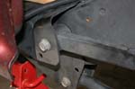
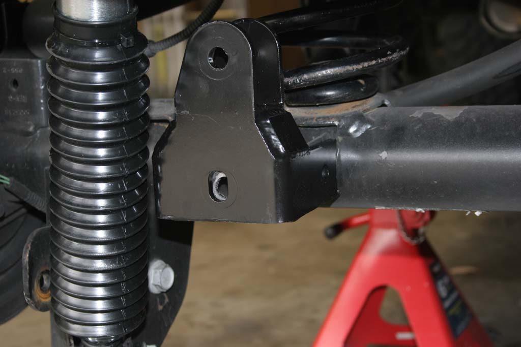
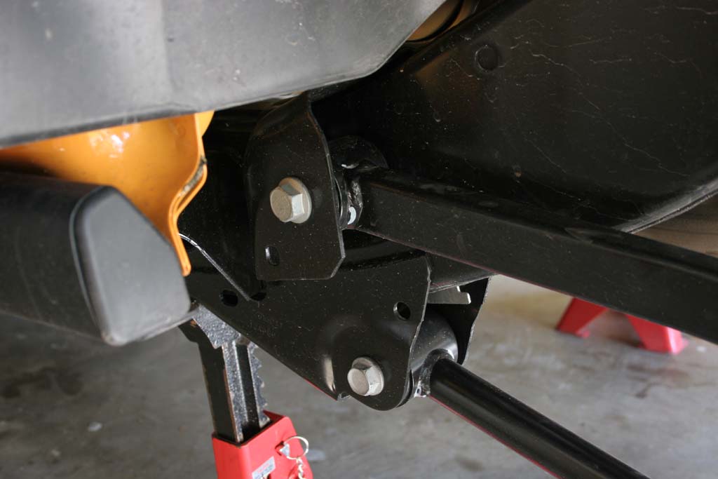
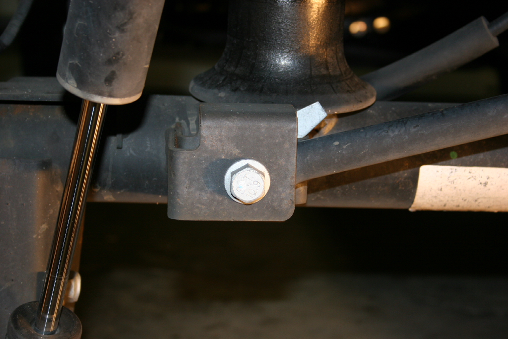
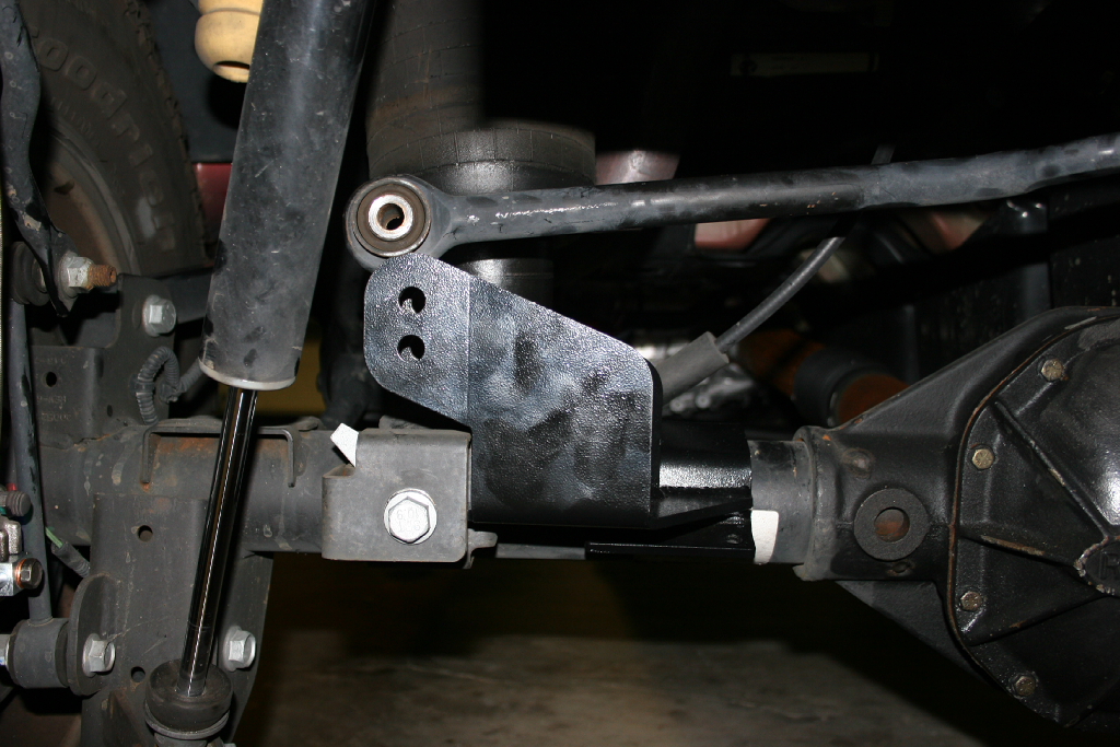
| 22. Install the rear track bar relocation bracket. |
 |
 |
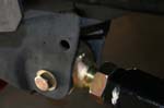
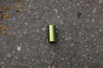
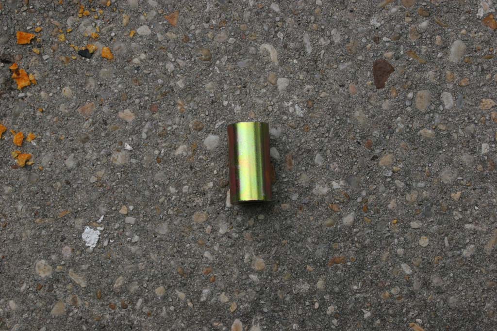
| 23. Attach the bracket using the OEM bolt with the supplied 7/8” O.D. x 9/16 I.D. x 1.625” Long crush sleeve on the inside of the OEM lower track bar mount |
 |
 |
 |
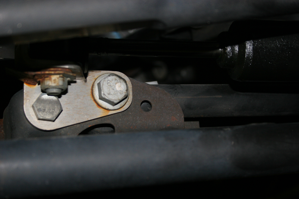
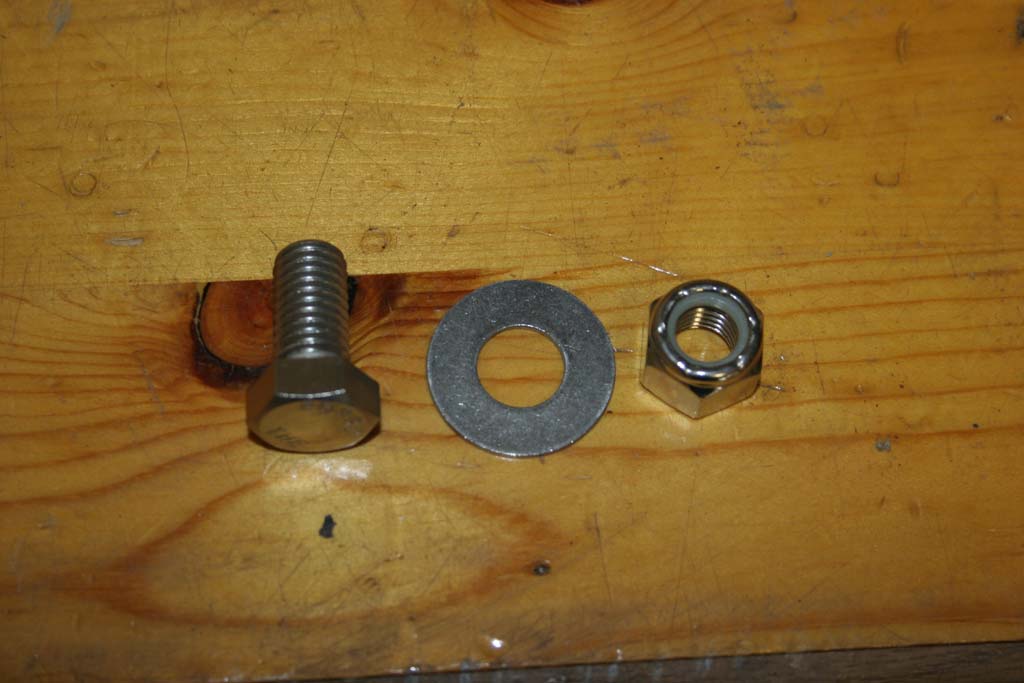
| 24. Drill a ½” hole through the inside of the factory bracket where the supplied hole in ther bracket is and secure that position with the supplied ½” x 1.25” long bolt, washers and nylok nut. |
 |
 |
 |
 |
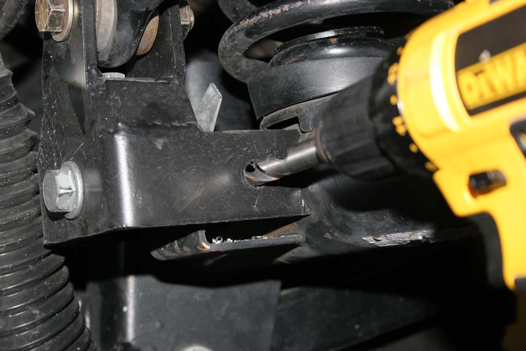
| 25. Drill a second 10mm (3/8") hole through the top of the OEM bracket where the existing hole is in the bracket. You may need to and secure it with the supplied 10mmx35mm bolt and 10mm nylok nut. |
 |
 |
 |
| NOTE: The bracket wings cup the OEM rear axle tube. This is due to the fact that the OEM factory rear track bracket is so weak. It is required before your first off-road adventure with your JK that these wings be welded to the axle tubes. This will prevent any failures of the rear track bracket assembly. |
 |
 |
| 26. Reinstall the trackbar using the factory bolt into the frame side bracket. You will need a 21mm socket and combo wrench. |
 |
| Bolt the trackbar into the RockKrawler trackbar bracket. You will need a 7/8" combo wrench or socket and 13/16" socket or combo wrench. |
 |
 |
| Rear Shocks: |
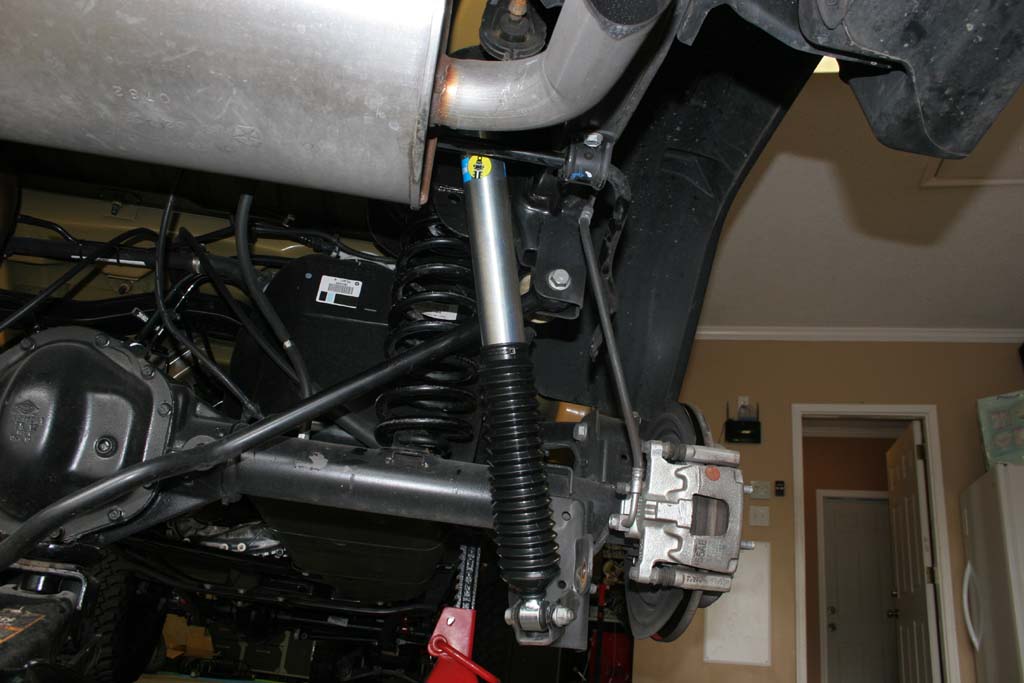
| 25. Install the new rear shocks. |
 |
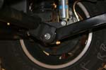
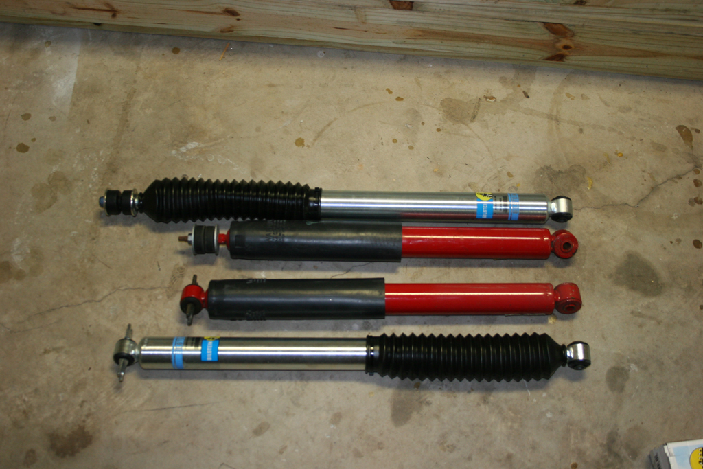
| 25a. Quick comparison shot between the new and old rubicon shocks. |
 |
| 26. Install the new rear shocks. You will need a 16mm socket and long extension for the top, and an 18mm combo wrench and socket for the bottoms. |
 |
 |
| Installed |
 |
| 27. Jack up the rear suspension and install the tires. We will do the brakelines later. |
| |
| Finishing up: |
| 1. Install the front and rear extended brake lines. You will need a 12mm to undo the hardline, a 15mm to remove the banjo bolt from the caliper, and 10mm socket to bolt the bracket in place to the frame. The 2012 and up models have long enough front brake lines that if you remove the bracket from the axle and remove the brake line out of the bracket. A little vise work makes it really easy. |
| 2. Bleed your brakes. |
3. Check and adjust your front track using the adjustable track bar.
Note: As you add weight to your front end, your track may change, so recheck it after adding things like bumpers and winches. |
4. If you installed adjustable control arms, you will need to adjust the caster. Put a jack under the front pinion and disconnect the adjustable end of both upper arms (or lowers if thats what you have). Adjust the front caster to 4.5 to 5 degrees using the jack. Adjust the arms and reinstall. They do not need to be exactly the same length. Getting a front end alignment will tell you more of where you actually are with your settings
NOTE: This is hazardous, so keep your body parts out of any pinch points and out from under the frame. I have had a pinion roll completely on me. |
5. If you installed adjustable control arms, you will need to adjust the caster. Put a jack under the rear pinion and disconnect the adjustable end of both upper arms (or lowers if thats what you have). Adjust the pinion so that it runs in line with the driveshaft at the rear axle. Adjust the arms and reinstall. They do not need to be exactly the same length.
NOTE: This is hazardous, so keep your body parts out of any pinch points and out from under the frame. I have had a pinion roll completely on me. |
| 6. Go through and tighten every bolt and nut your removed and reinstalled, tighten the control arm and adjustable trackbar jam nuts. Recheck them at about 100 and 500 miles. |
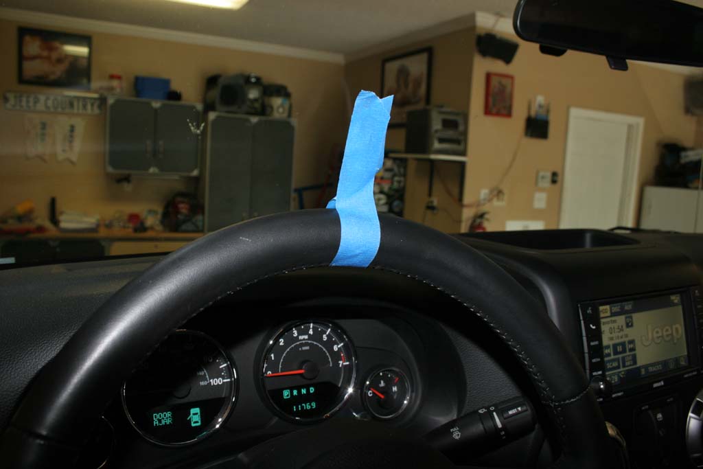
| 7. Adjust your steering wheel to have it centered and straight. You will probably need to adjust it out about 2.5 turns. Put a piece of blue tape in the center top of your steering wheel, that way you can just look through the windshield as you make adjustments and not have to walk around the side of the Jeep. You will need to drive it and fine tune it a couple of times. |
 |
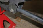
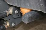
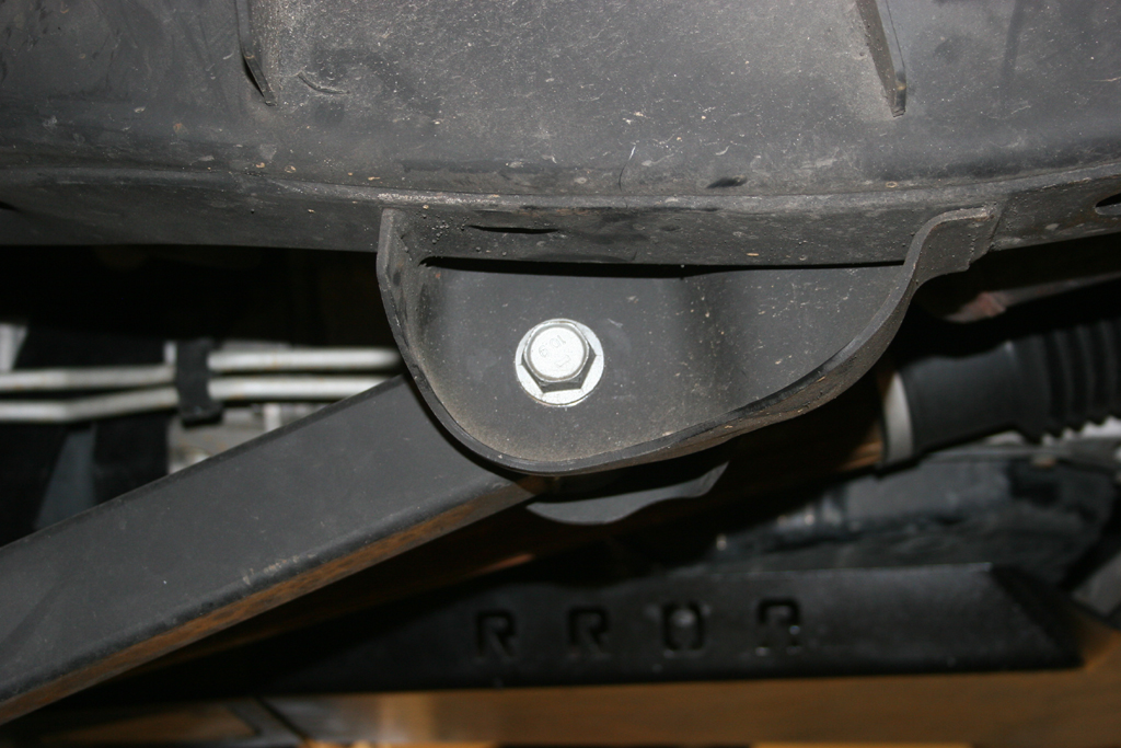
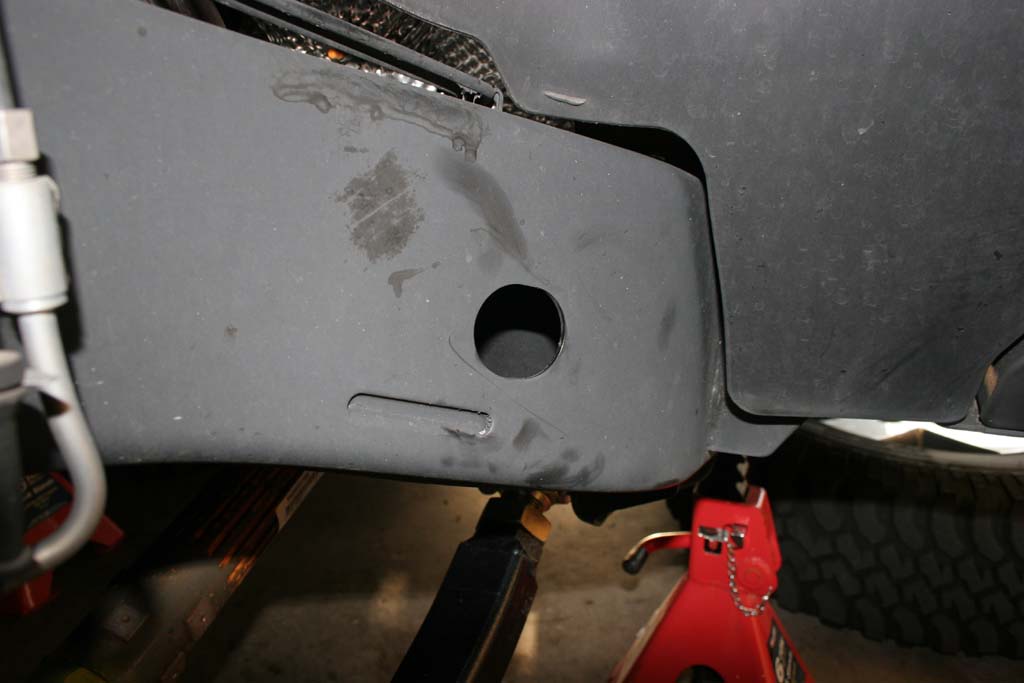
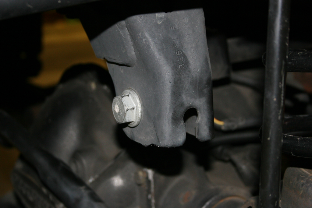
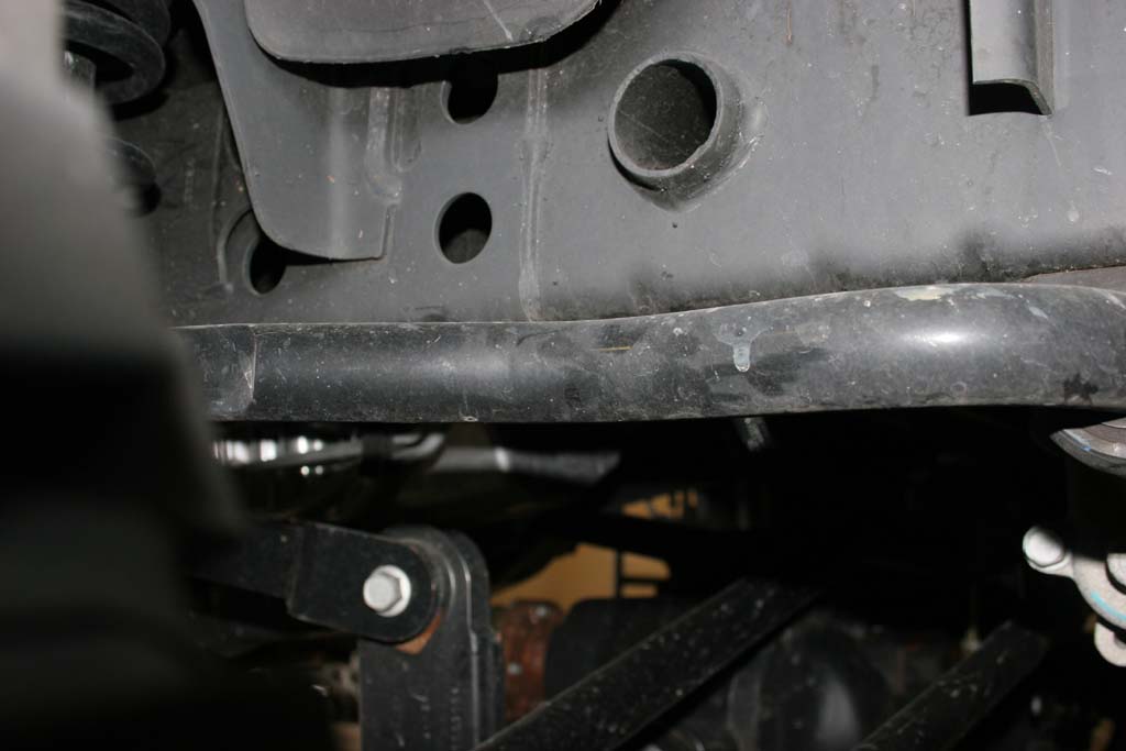
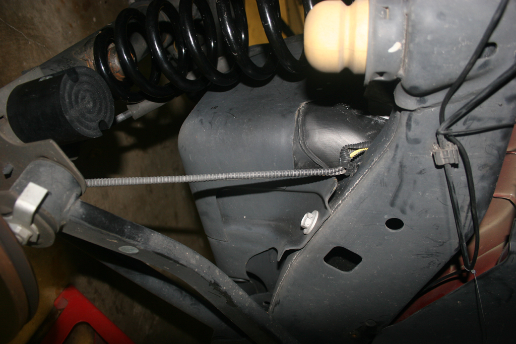
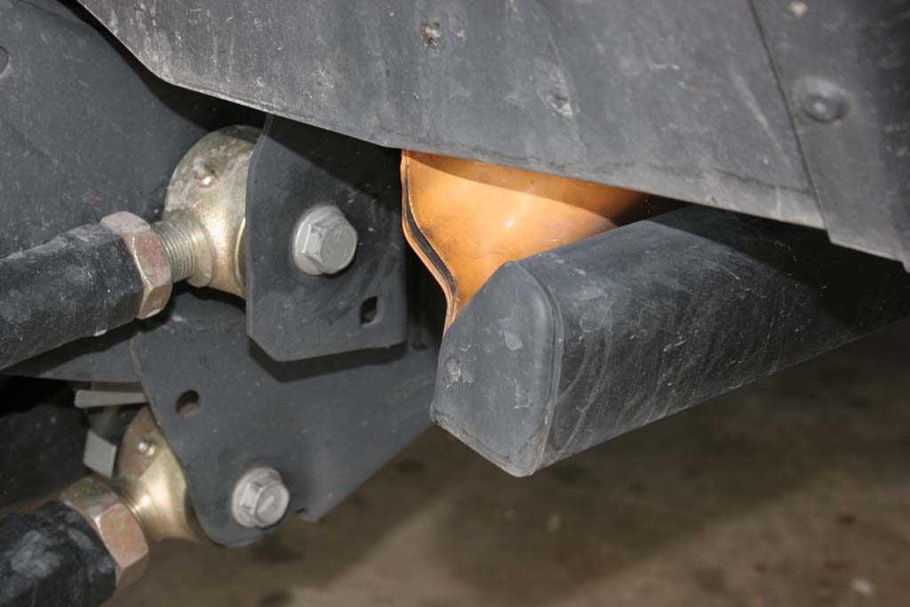
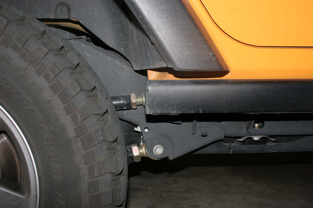
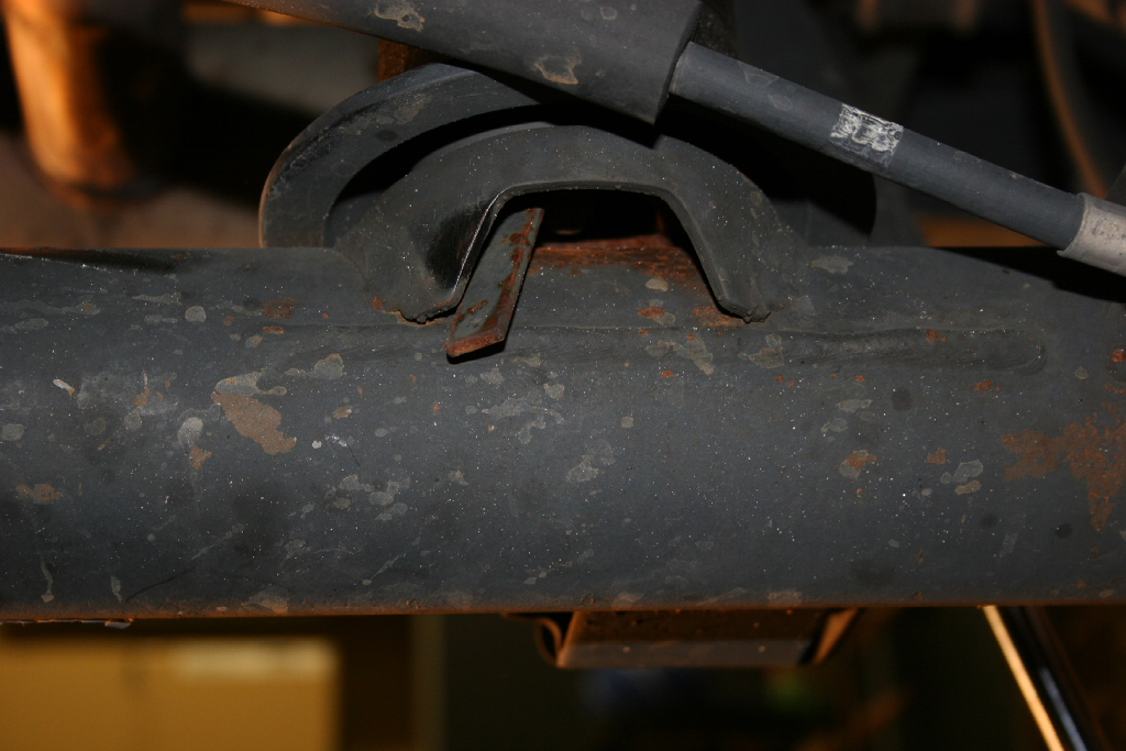
| 8. Check your clearance on the rear pinch seam. |
 |
 |


