The biggest problems with installing
an OBA system is finding a location to mount all of the parts for it,
and actually assembling all the individual parts to make it up. We face
these things with the limited space in a Jeep thrown in on top of it.
The most mounting area we have is under the hood, where these components
are subjected to a lot of heat from the engine. I spent some time researching
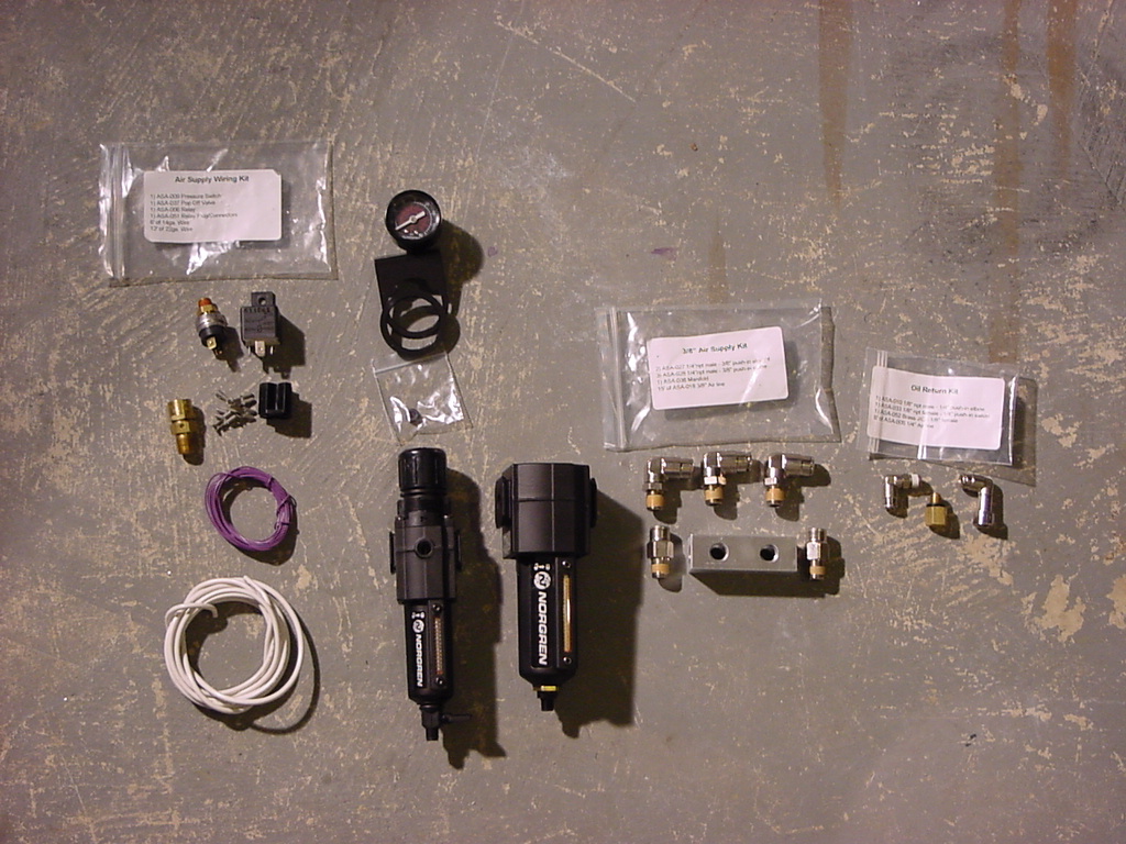
the individual parts that I wanted to use to make this system up and it
pretty much came down to ordering a bunch of parts from Kilby's, or getting
the Air Kit from Off Road Only. I opted for the kit from Off Road Only
for several reasons, the heavy duty braided compressor discharge hose,
and the Norgren pressure regulator and Oil filter (with automatic oil
return).
| Installation: |
Laying
out the system:
I first decided where I was going to mount the major components:
Air Tank, Pressure Regulator, Oil Filter, Manifold and Relay. I
figured that everything except the tank would go under the hood.
The limitation under the hood is the distance of the Compressor
Discharge hose to the Oil Filter. I do have the bracket for the
Automatic Transmission Computer installed under the hood. This bracket
originally was the mounting point for my Painless wiring harness
that didn't quite withstand the heat under the hood, I found the
resin melting out of it and some scorching on the connectors, so
I removed the harness. My intentions are to install a marine grade
harness into the Jeep later. |
|
|
|
|
|
|
|
|
| |
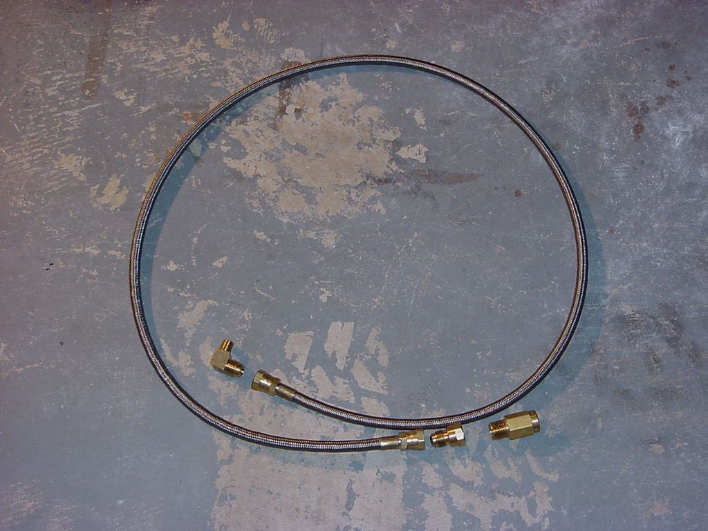
Installing
the Compressor Discharge Hose:
|
 |
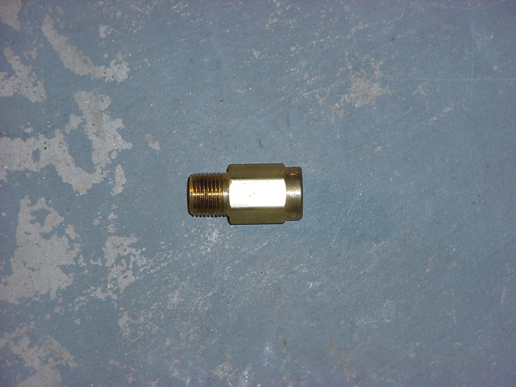
| Install
the check valve on the installed compressor discharge fitting. This
requires a 1" Combo Wrench, or a 12" adjustable wrench.
You may need to Teflon tape the threads. |
|
|
|
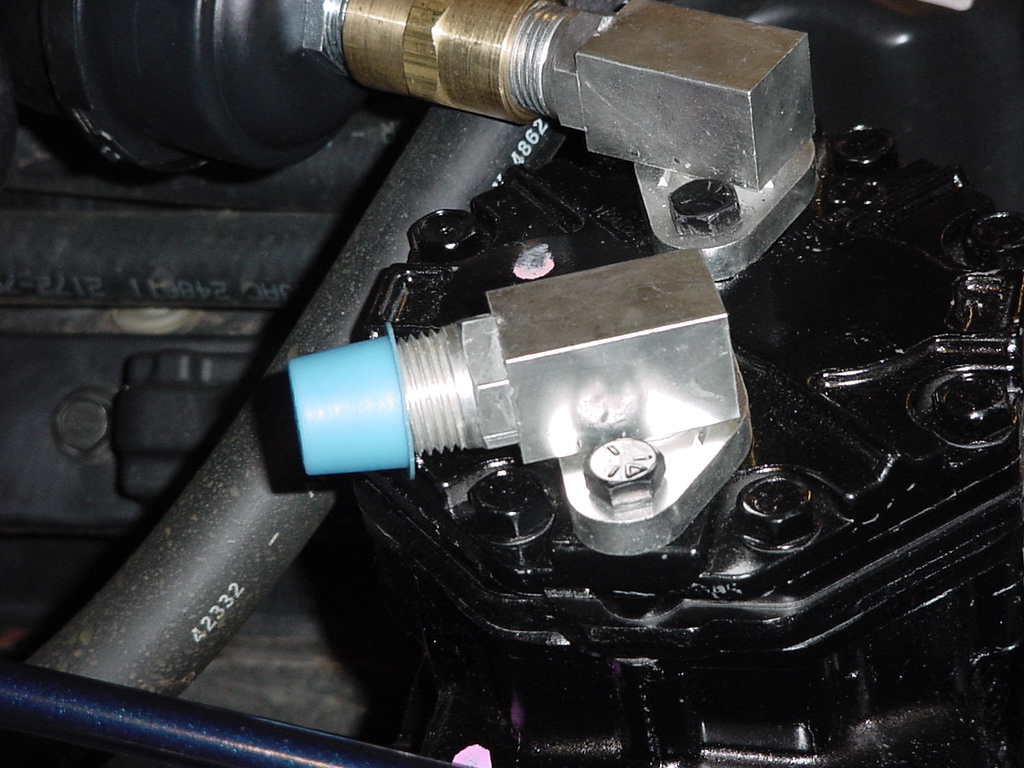
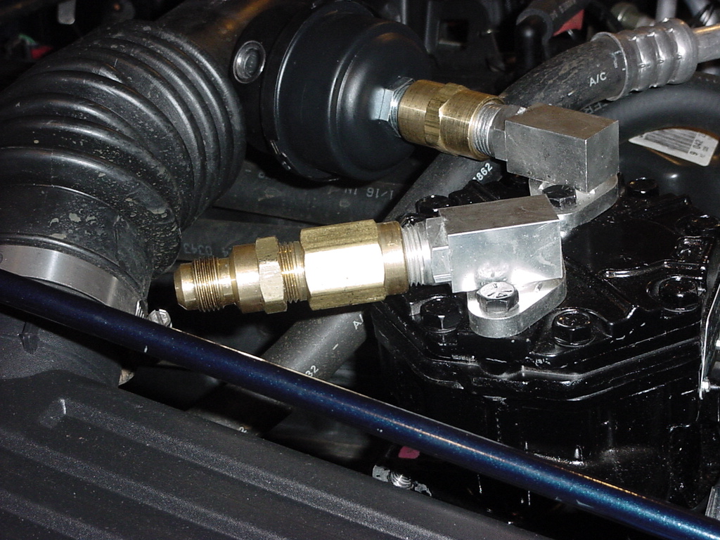
Install
the compressor discharge hose adaptor fitting to the check valve.
You will need a 15/16" Combo Wrench for this and either a 1"
Combo Wrench or 12" adjustable wrench to hold the check valve.
|
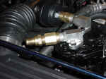 |
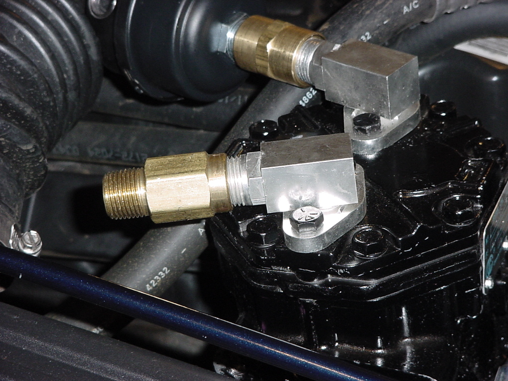
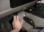
Install
the compressor discharge hose on to adaptor fitting. You will need
a 7/8" Combo Wrench and a 15/16" Combo Wrench to hold the
adaptor fitting. The hose rides against the connection of the
air filter box. This causes a little wear on the air box since it
is only plastic. I do believe that if I had only a 1" body lift
vice 1 1/4" I would not get any rub.
|
|
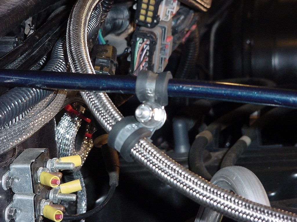
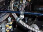
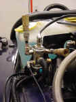
| Route the Compressor Discharge Hose along the firewall to the driver
side. This will give you a good determination as to the location of
the oil filter. I had enough to allow for a loop back into the oil
filter. I used (2) 1/2" rubber insulated clamps to hold
the hose and (2) 3/8" rubber insulated clamps to connect to the
grill support rods. This provided good support of the hose and allowed
for some flex in the hose during run of the compressor and movement
of the engine. I will keep an eye on the clamp closest to the compressor
to see if there is any wear from the heat and vibration. I used
a 1/4-20x3/4" bolt, (2) 1/4" washers and a nylon insert
lock nut. These require a 7/16" Combo wrench and socket. |
 |
| |
Mounting
the Oil Filter:
|
|
| Since
I had already determined that filter would not fit in the available
space on the Auto Computer Bracket I still needed a place to mount
the Oil Filter. I still didn't want to make a bracket for it and I
was limited as to the distance that I could put it away because of
the compressor discharge hose so I decided that hanging it off of
the grill support rod right by the Cruise control module would be
a good location. I did this by utilizing (2) 3/8" rubber insulated
clamps around the grill support rod and bolting the bracket to them.
Once again this was bolted on using 1/4-20x3/4" bolt, (2) 1/4"
washers and a nylon insert lock nut. These require a 7/16"
Combo wrench and socket. |
 |
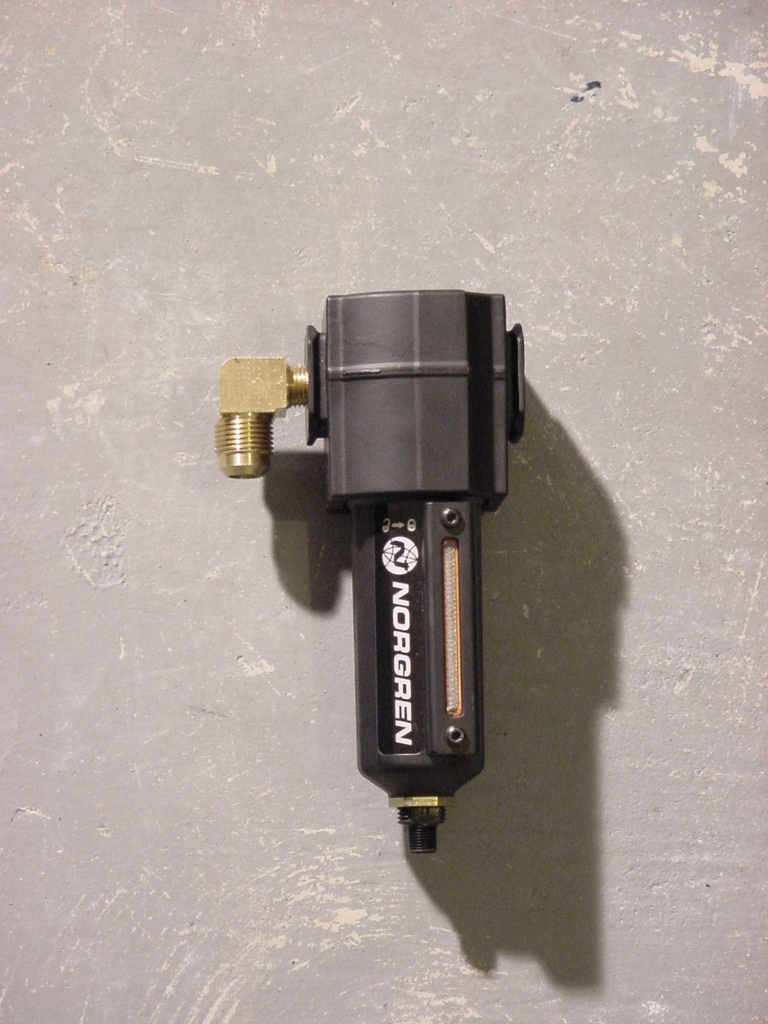
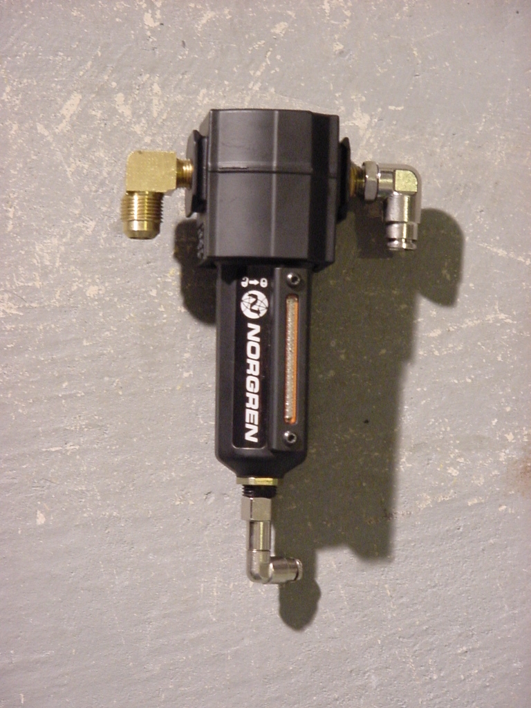
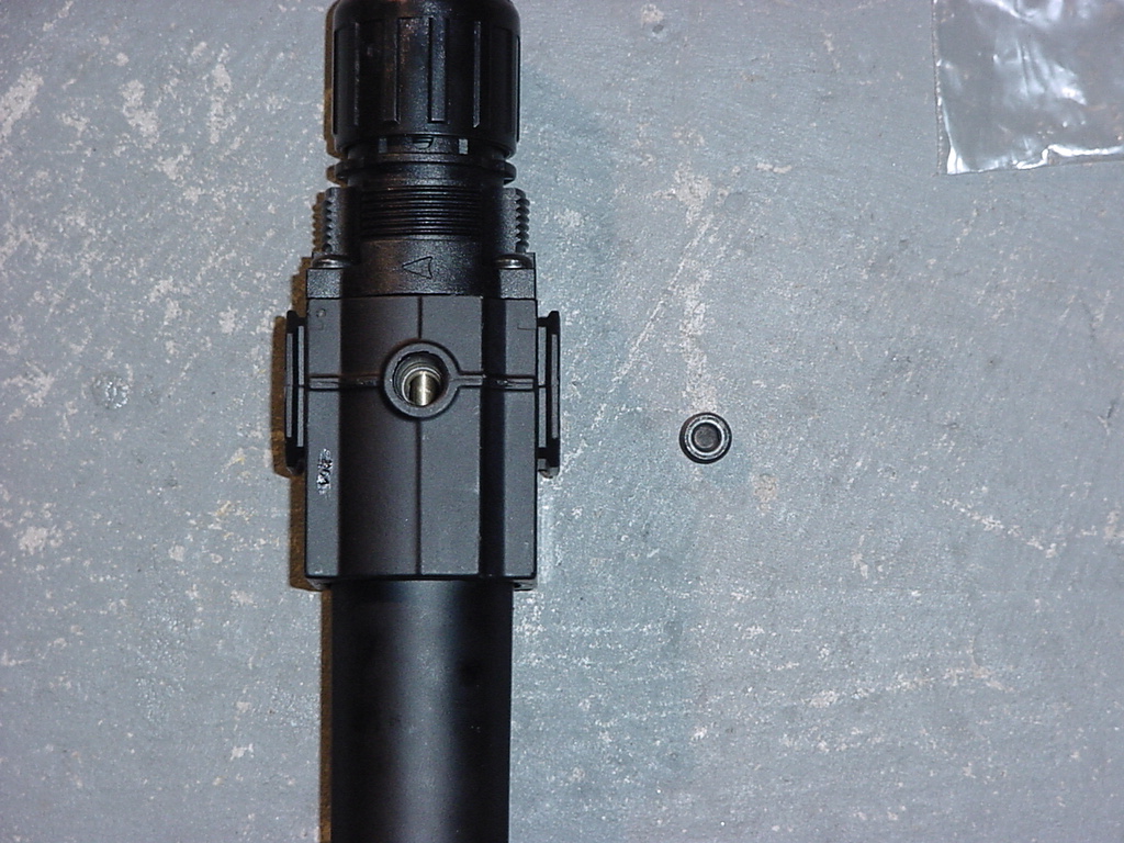
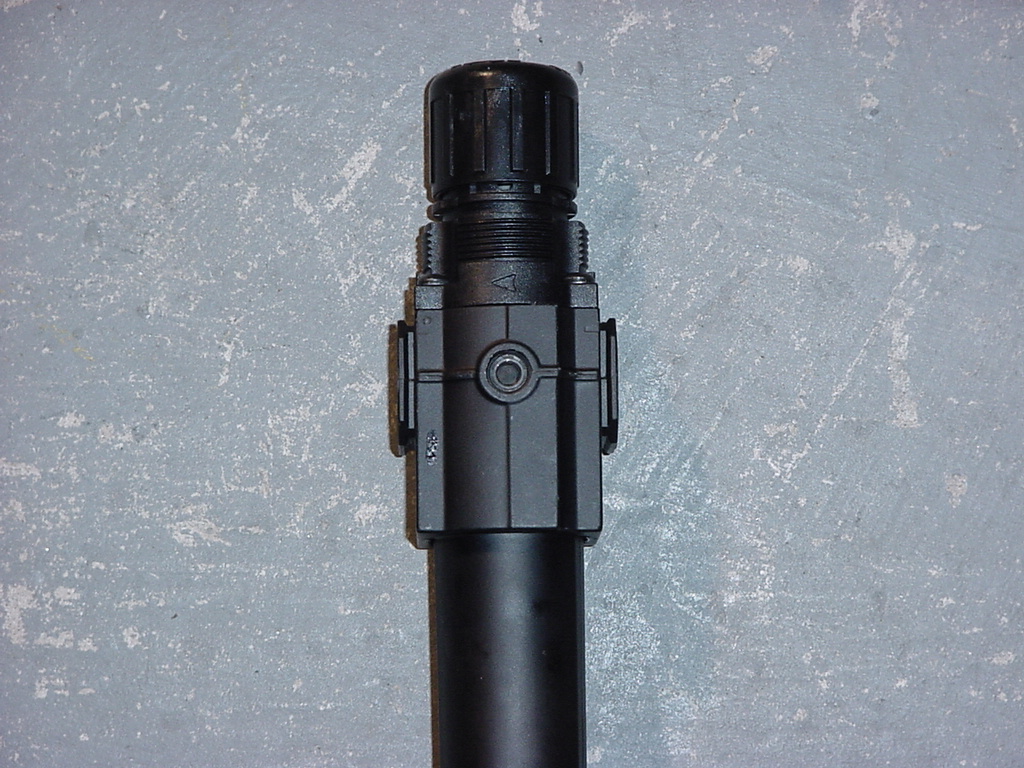
| Take
a look at your oil filter. There should be a direction arrow
stamped into the body, or a marking indicating the inlet to the filter.
The Norgren filter has an arrow stamped into it.. You will install
the compressor discharge hose fitting into the inlet side. |
 |
Install
the 90 degree compressor discharge hose outlet adaptor into the
inlet side of the oil filter. I had to rotate the bowl assembly
around when I installed it in the Jeep. I used the 12"
Adjustable wrench to tighten this down. |
|
|
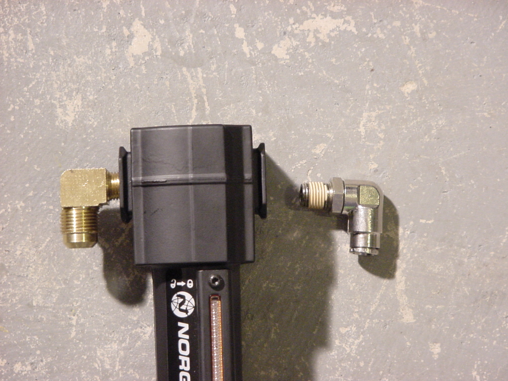
| Install
a straight air line fitting in the outlet side of the oil filter.
I originally installed one of the 90 degree fittings and later found
that my routing didn't work quite right with it. You will need
an 11/16" Combo Wrench. |
|
|
|
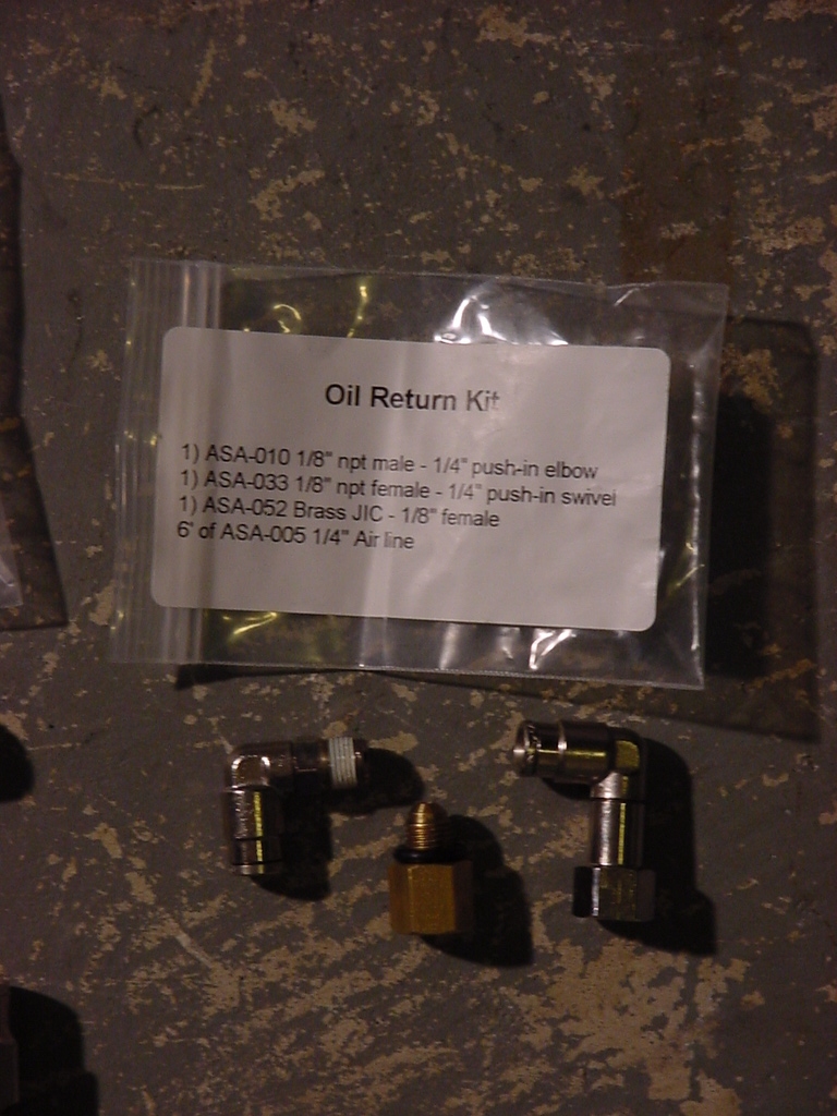
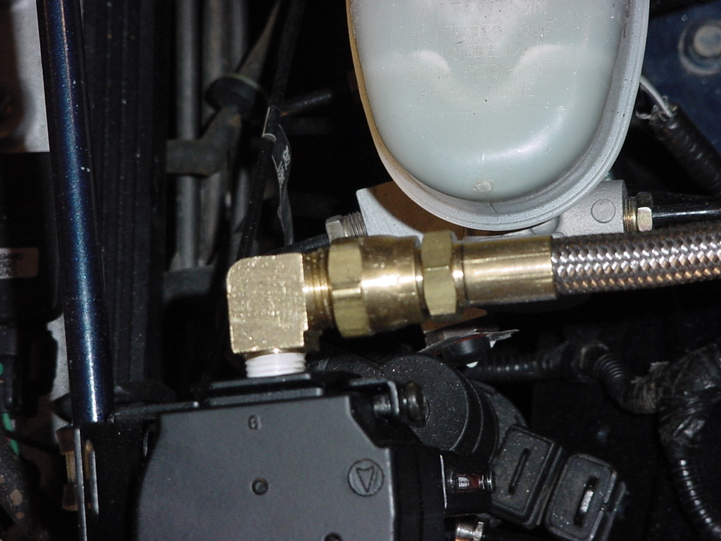
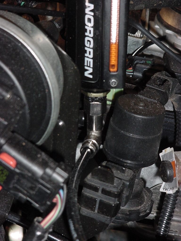
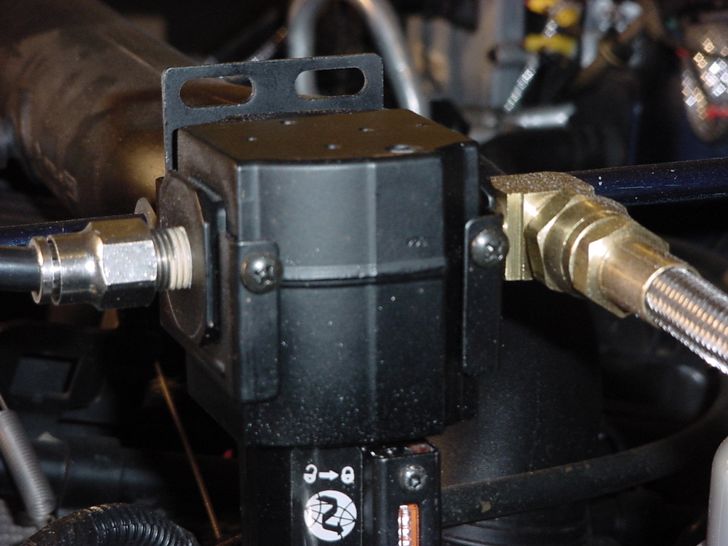
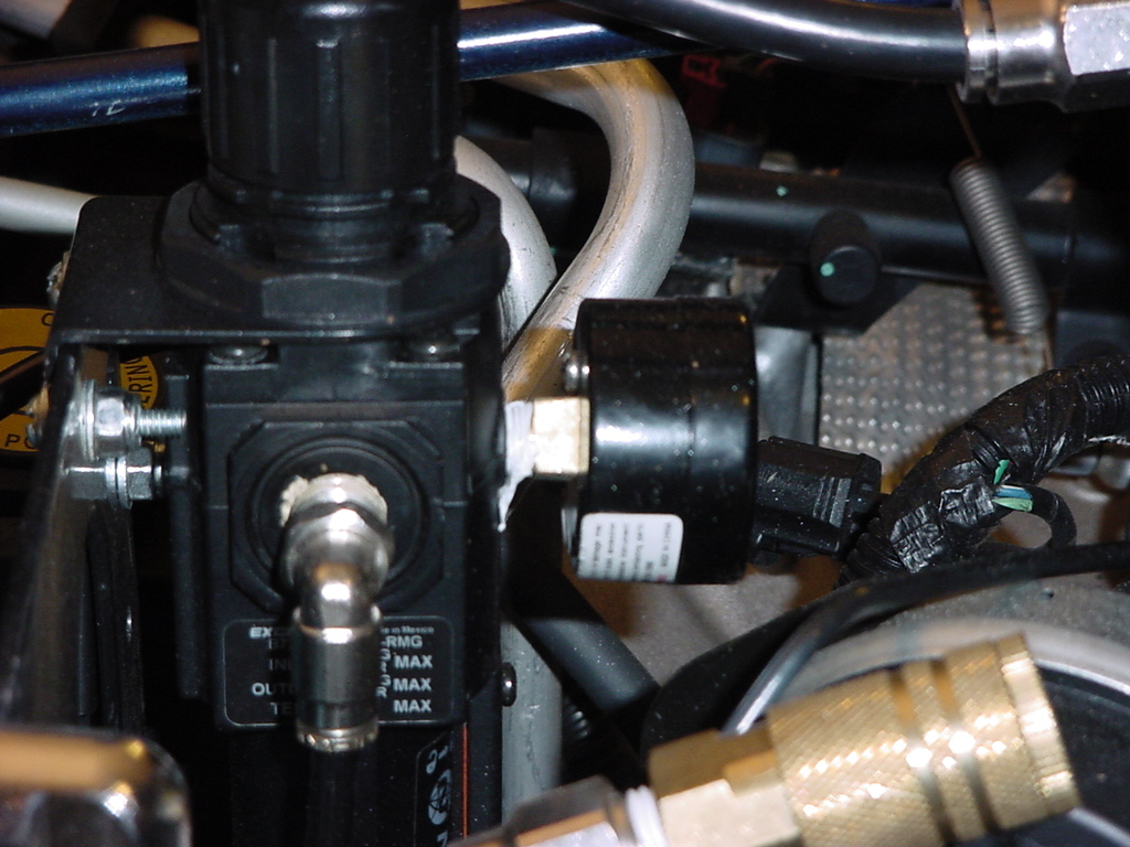
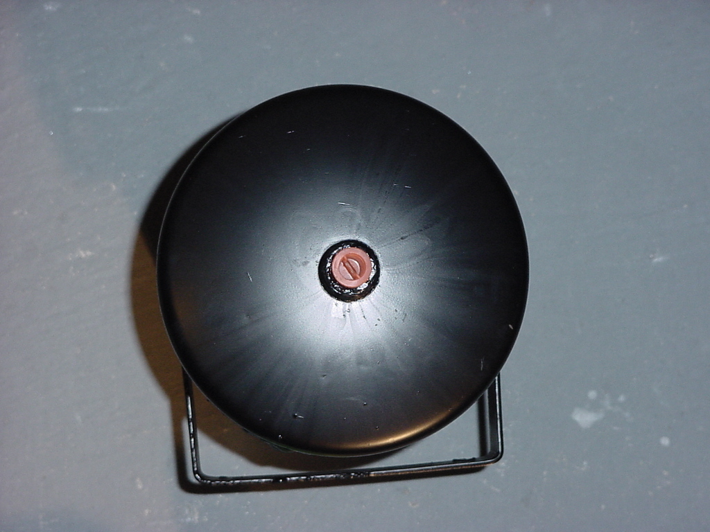
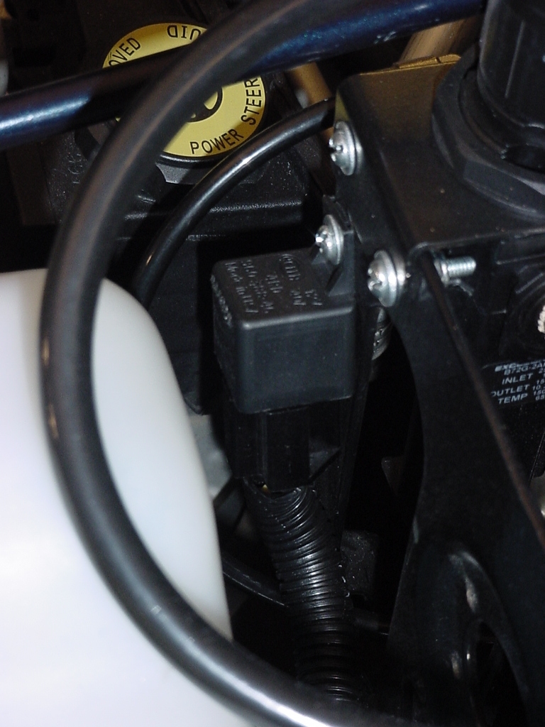
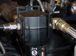
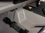
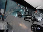
| Install
oil return fitting to the bottom of the oil filter. As you can
see with it installed in the location, it fits perfectly into the
hole. Be careful, the connection on the bottom of the filter
is plastic. I used a 9/16" Combo Wrench. You will
also need to install the brass fitting and other connector into the
side of the York Air Compressor. |
|
|
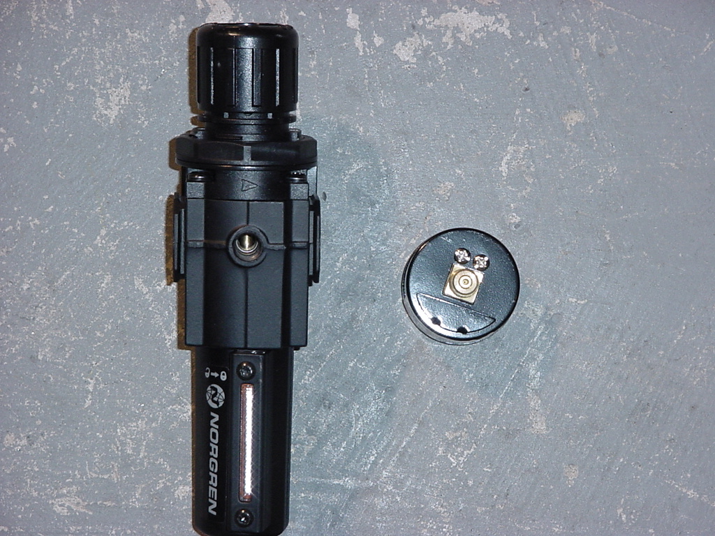
| The
Oil Filter just rests in a bracket. I didn't like this since it seemed
that it could easily jump out of the bracket or just move around in
it. There were 2 small black screws that came with the filter, and
didn't seem to fit in any of the holes except the two in front, so
I screwed these in to hold the filter in place. The holes are not
pre-tapped, so I only assumed that the screws went here. Of
course you use a phillips screwdriver to install these. |
 |
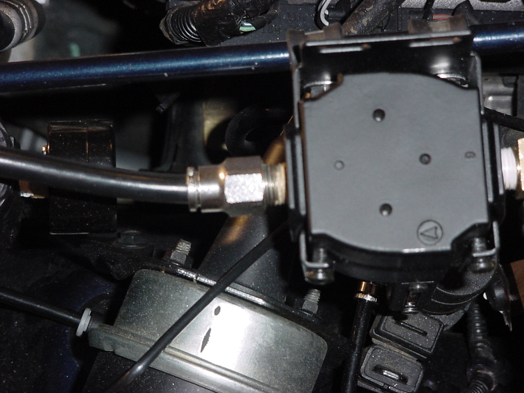
| Connect
Compressor Discharge hose to oil filter inlet. You will need
a 7/8" Combo Wrench and a 15/16" Combo Wrench to hold the
adaptor fitting. |
|
| |
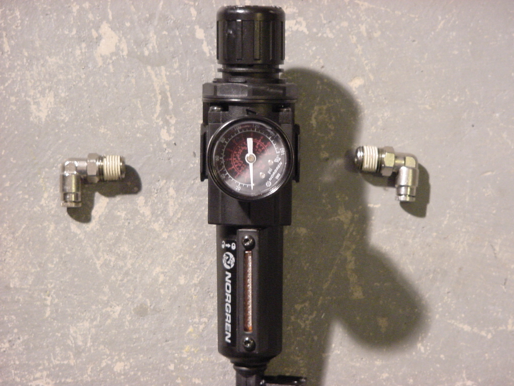
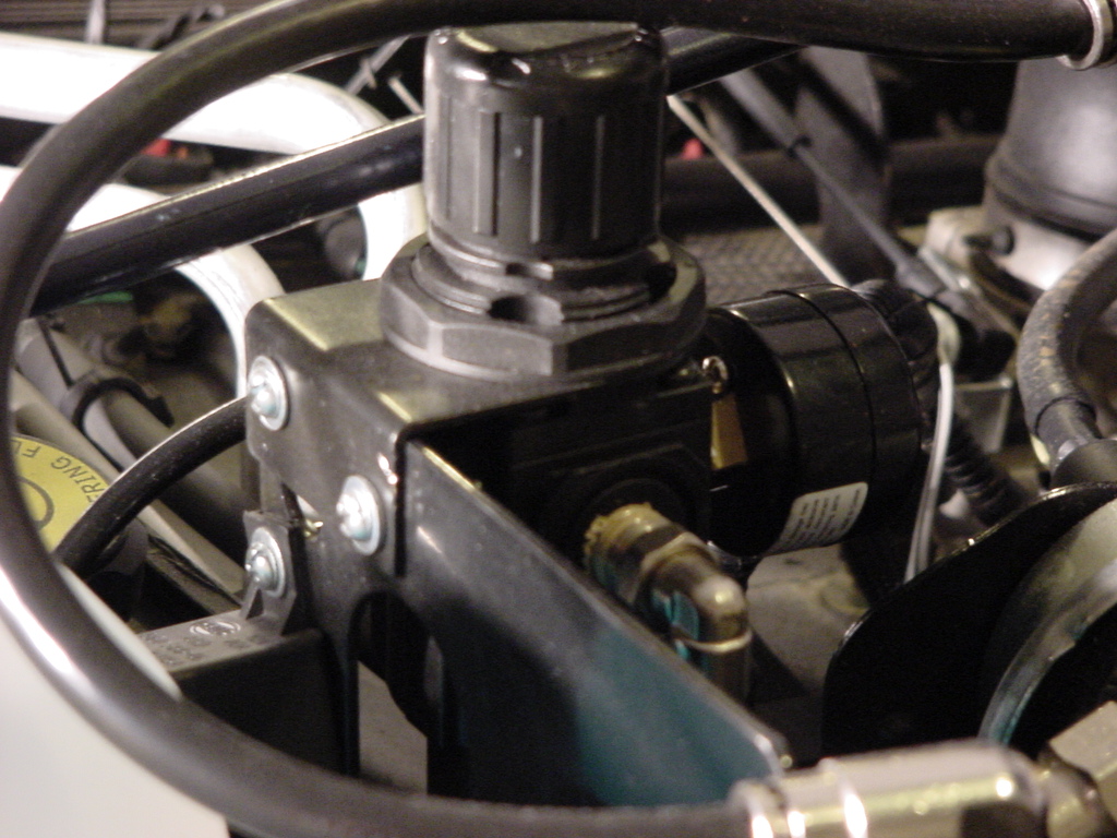
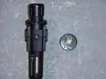
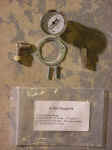
| Mounting
the Pressure Regulator: |
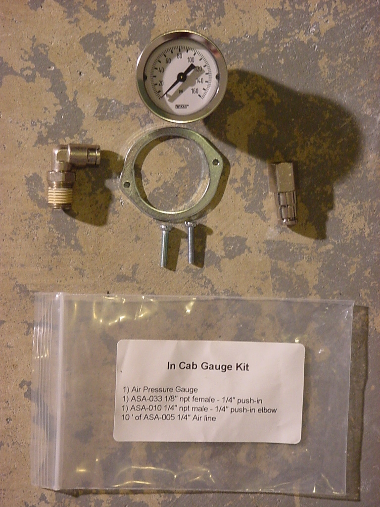
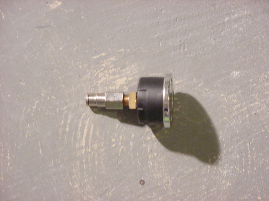
Install the pressure gauge on the regulator. I installed it with
the regulator outlet to the right. This required a 7/16"
Combo Wrench. I didn't get the gauge positioned perfectly,
but it's more important that the gauge doesn't leak. |
 |
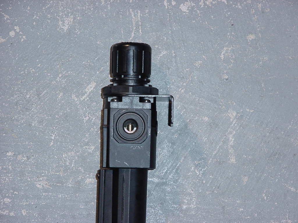
| Install
plug on opposite side. You may need to Teflon tape the plug before
installing it. This requires a 3/16" Allen wrench. |
|
|
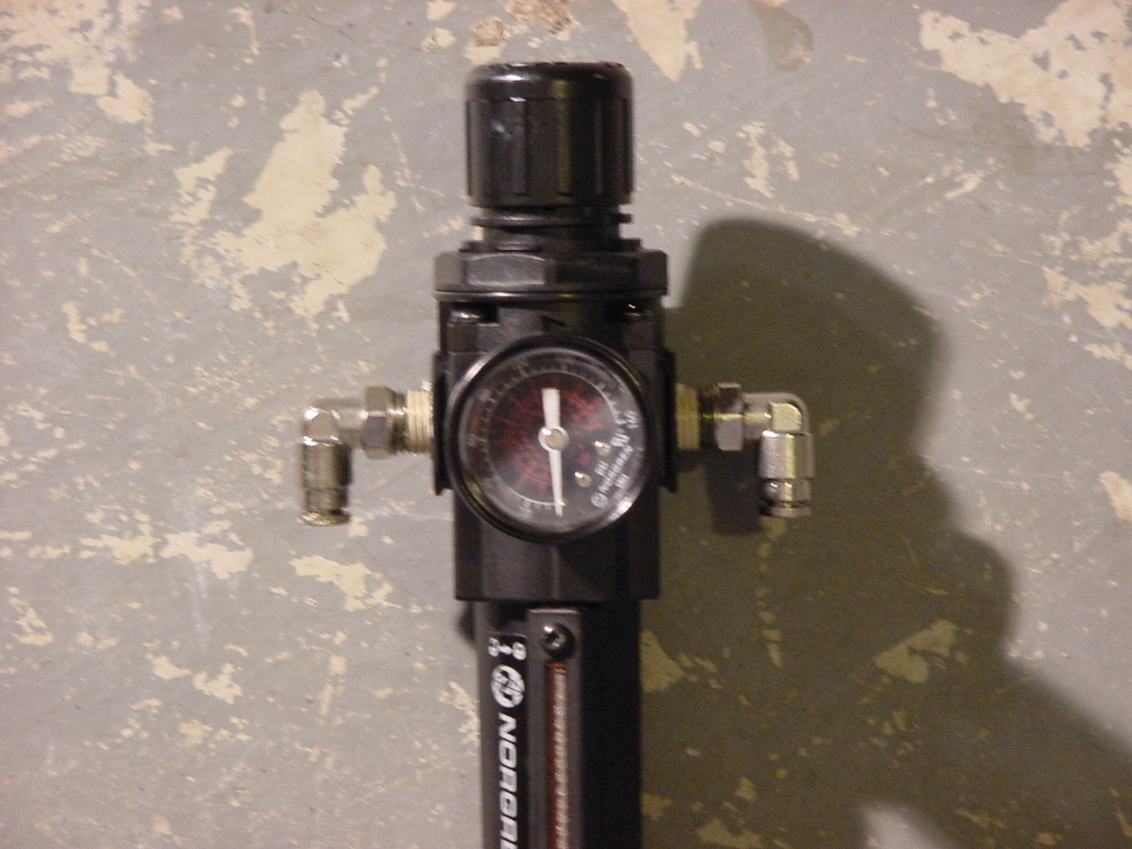
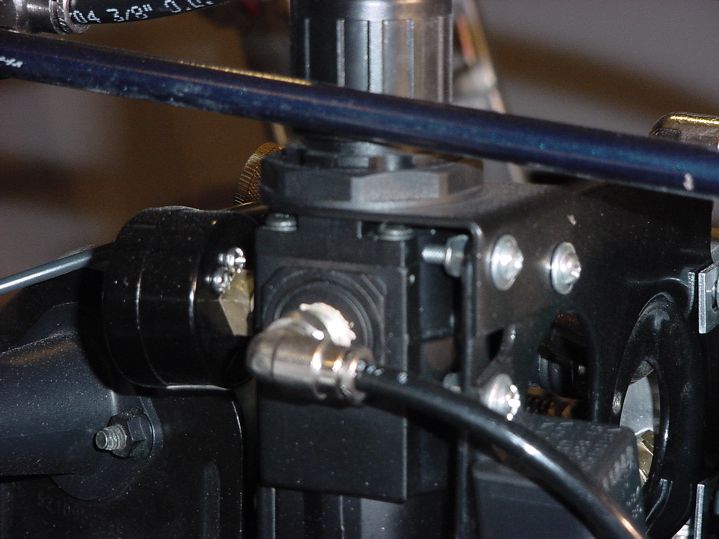
| Install
(2) 3/8" 90-degree fittings onto Pressure Regulator. I
used a 9/16" Combo Wrench. |
|
|
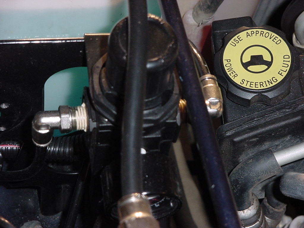
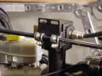
| Install
regulator support bracket on regulator. I installed it with the L
pointed down. The bracket only goes on with the mount holes in the
front or the rear. |
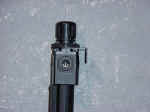 |
I
needed to mount it with the bracket up and over the lip of the Computer
Bracket. This allowed the regulator to be located closer to the
auto computer bracket. I marked and drilled the holes with a 3/16"
drill bit. I then used (2) #8-32x3/4" machine screws,
(4) #8 washers and (2) #8-32 Nylon insert lock nuts to hold it in
place. You will need a phillips screwdriver and an 11/32"
Socket or Combo Wrench. |
|
|
|
|
| |
| Mounting
the Manifold: |
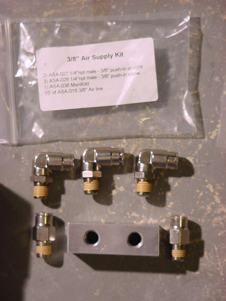
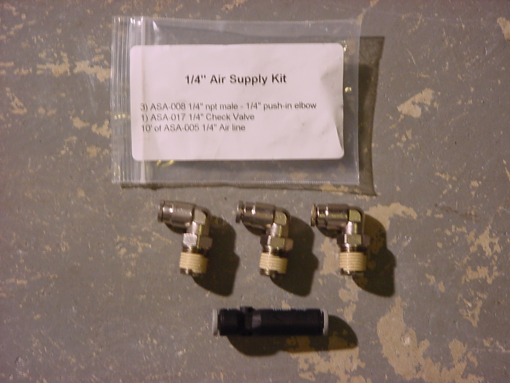
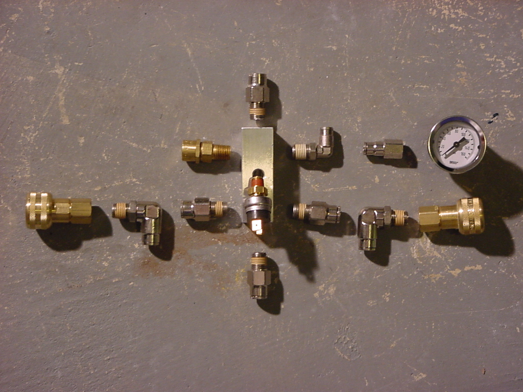
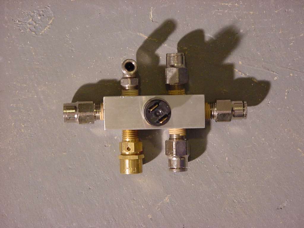
| Install
the fittings in the Manifold. Some fittings may require Teflon
tape to be applied before installation. With the limited space provided.
I decided to install the (4) 3/8" 90-degree elbows that came
with all the parts of the kit onto the manifold. The manifold has
(6) 3/8" holes (1 in each end and 2 on each side) and (1) 1/4"
Hole (in the top) drilled in it. The 1/4" hole is used for the
pressure switch. I installed a 3/8" 90-degree elbow in each end
and 1 in each side of the manifold (ended up being opposite side corners
from each other). I installed the safety valve in the lower hole on
what would be the inboard side and the connection for the air line
to the in cab air pressure gauge in the other. I installed this fitting
on the outside of the manifold so that I could later change it if
I decided to go with a digital gauge vice the mechanical one.
Installing the fittings into the manifold will require an 11/16",
5/8", and 9/16" Combo Wrenchs. |
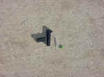
| This
was my first set up that I had arranged. Though after installing
everything I realized that my arrangement didn't work in the area
provided. |
 |
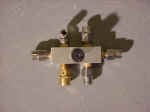 |
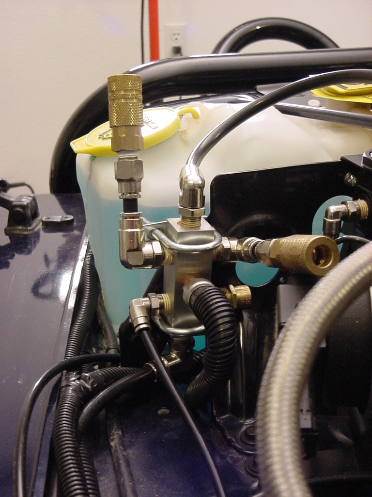
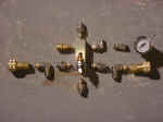
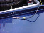
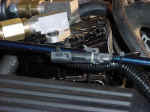
| So
this is the octopus that I finally ended with. The air chucks
are just installed temporarily in this picture until I route them
to their permanent location. The one that is pointed up actually
rotates down so that I can close the hood. |
 |
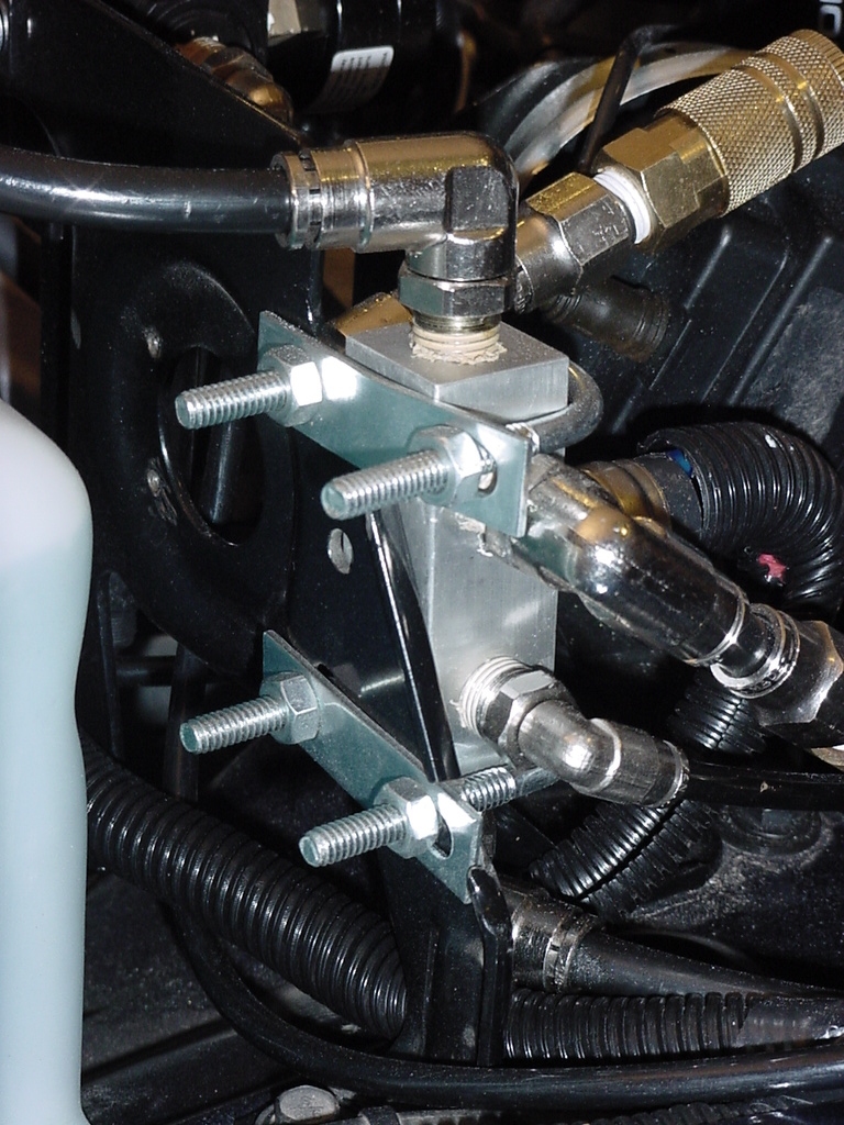
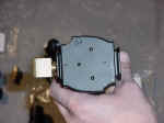
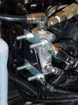
| The
Off Road Only Manifold does not have any mounting holes in it, so
I decided to use some 1 1/8" U-bolts to hold it on to the Auto
Computer Bracket. I tried to get a good location where I could mount
with all 4 ends of the U-bolts, but could only get 3 good ones. I
mounted the Manifold vertically on the outer edge of the Auto Computer
Bracket. I needed to trim down a couple of the edges to get the U-bolts
to sit right. I marked and drilled the holes with a 1/4"
drill bit and tightened the nuts with a 7/16" Combo Wrench.
You will need to trim down the ends of the bolts. I am still
looking for some square U-bolts to fit this better. |
 |
|
| Mounting
the Tank: |
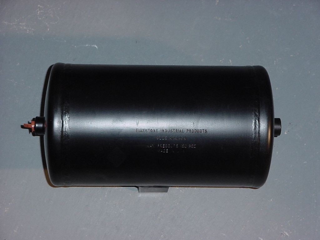
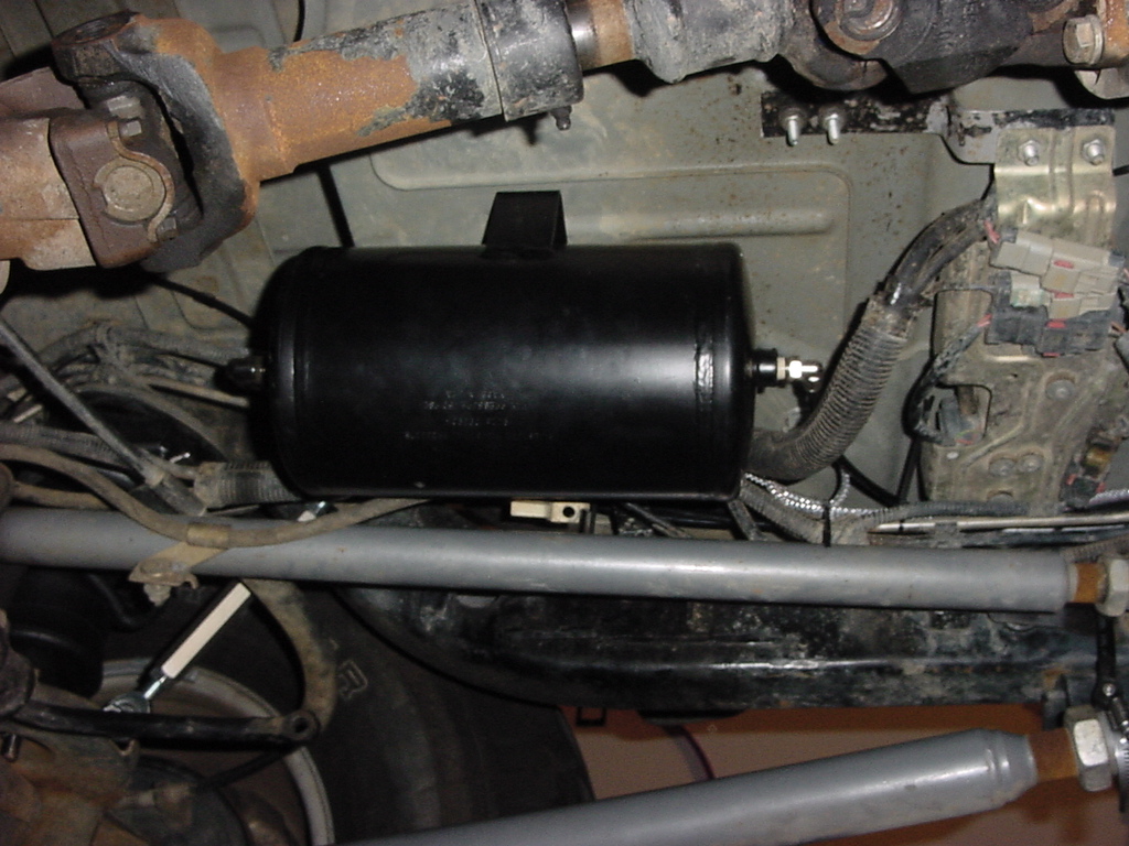
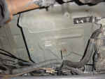
| Now
the 1 gallon tank was for a test purpose so I needed to look for an
area where I could later install a larger tank if I wanted to. This
eliminated installation under the hood and since I didn't have a tire
carrier or the desire to mount it in the back of the Jeep with the
seat removed, I was pretty much limited to installing it under the
rear floor pan just behind the transfer case on the driver side. This
space has been used before for installation of compressors on other
Jeeps with no ill effects. It is fairly well protected in this location. |
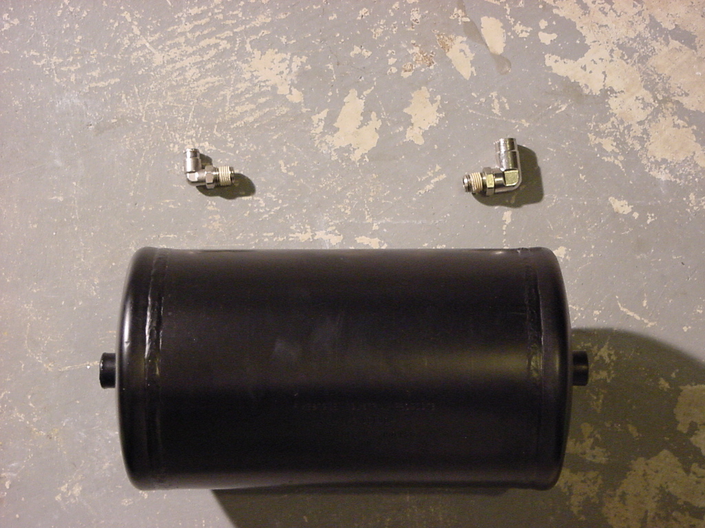
| Remove
the plastic caps from the ends of the tank. I needed a pliers
to pull these out. |
|
|
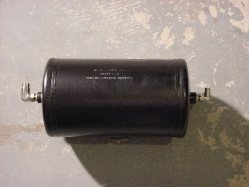
| Install
fitting into the end of the tank. One 90 degree fitting supports
that large tube diameter, and the other 90 degree fitting supports
the smaller tube diameter. This fitting will go to the pressure
regulator. You will use an 11/16" Combo Wrench to install
these. |
|
|
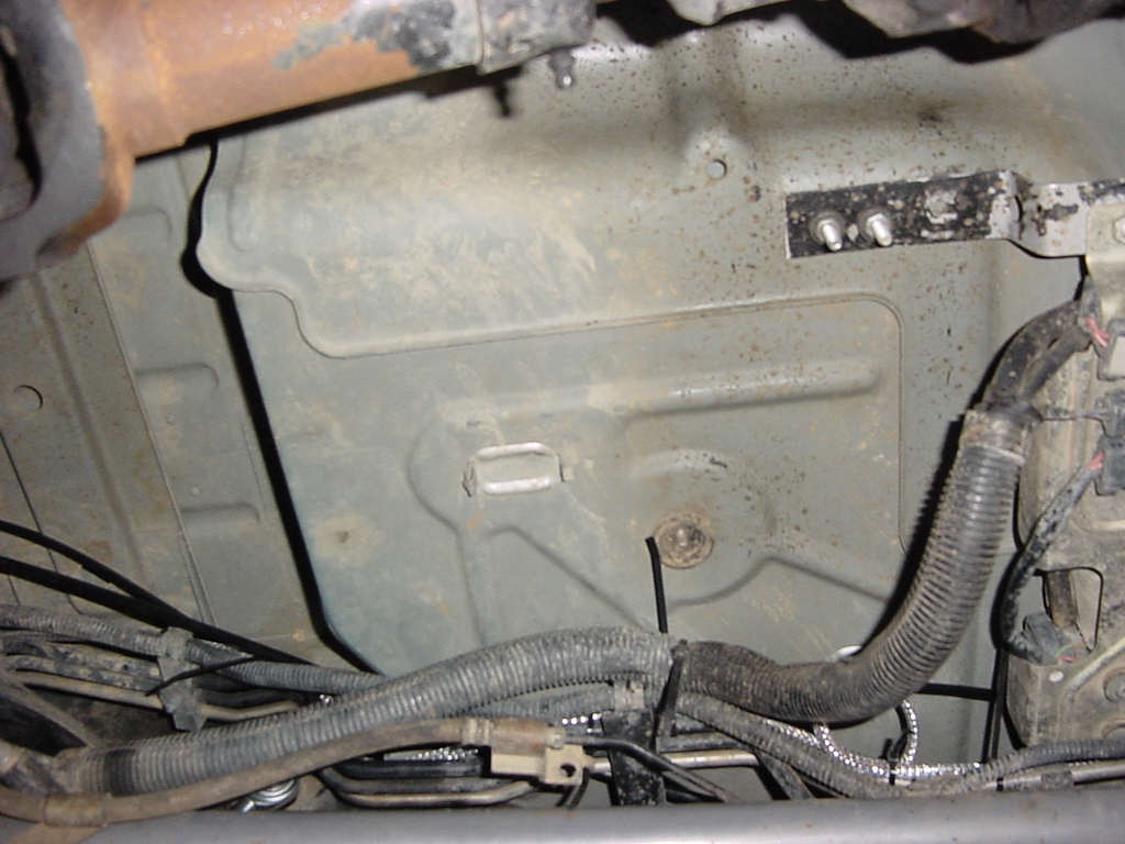
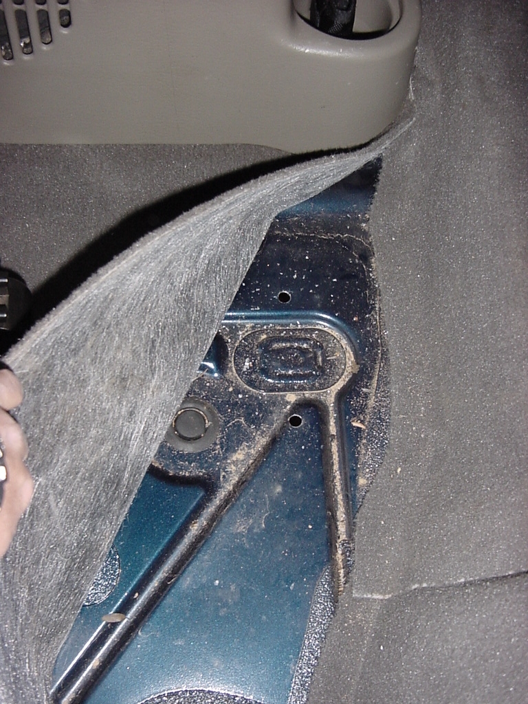
| Hold
the tank up into position and mark the location of the mount holes
for the Tank brackets. |
 |
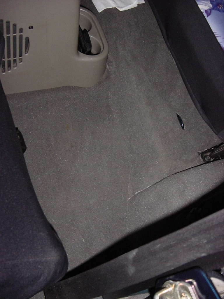
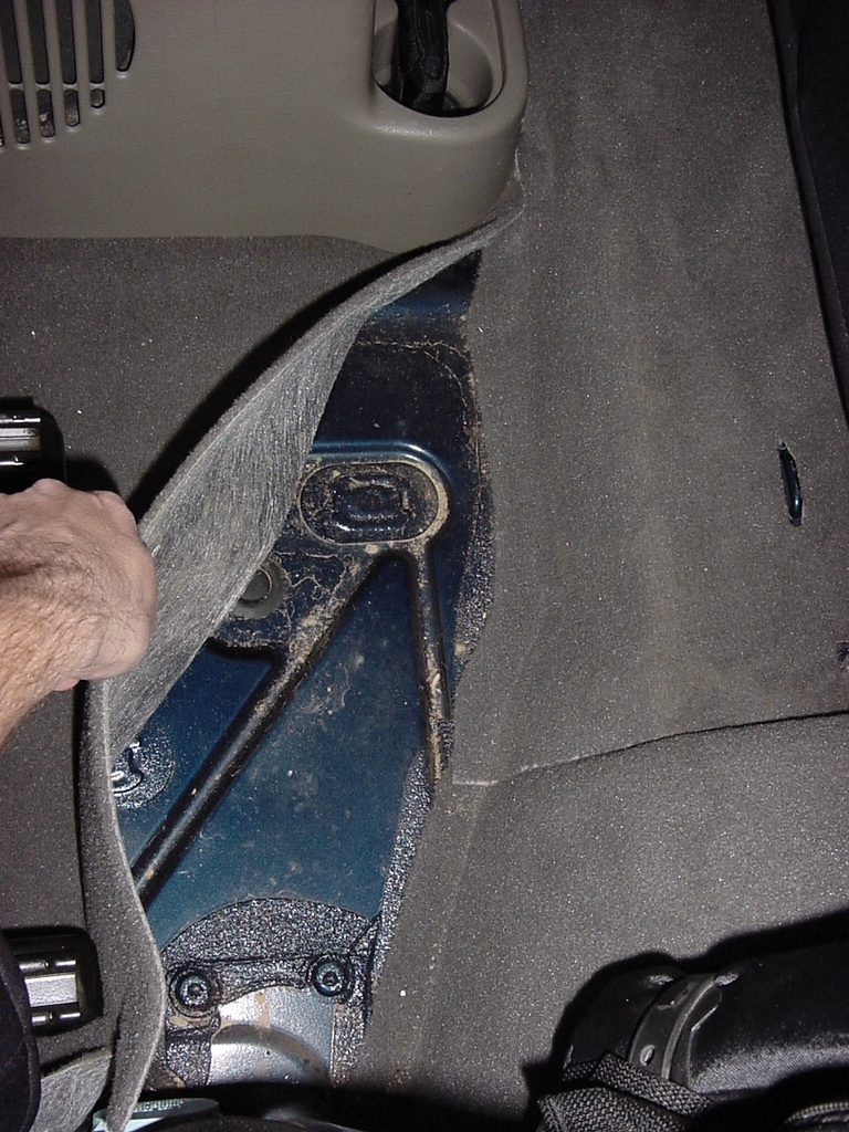
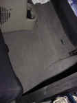
| Pull
back the carpet from inside the Jeep to check for any obstructions
and to prevent damage to the carpet. |
 |
 |
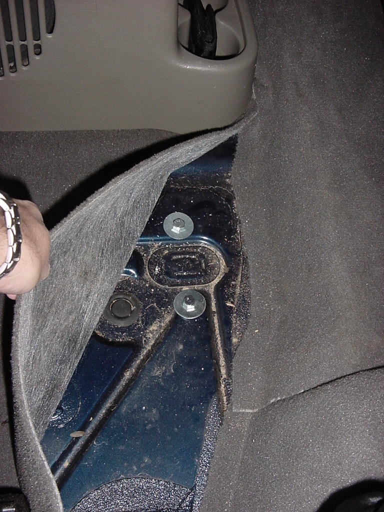
| Drill
through the floor pan. The drill bit size and bolts will depend
on your tank size. |
 |
Install bolts and nuts to secure tank. This may require a second
person unless your really ingenious or Mr. Fantastic with rubber
arms. I used some large fender washers to help spread the
load over the floor pan. |
|
|
| |
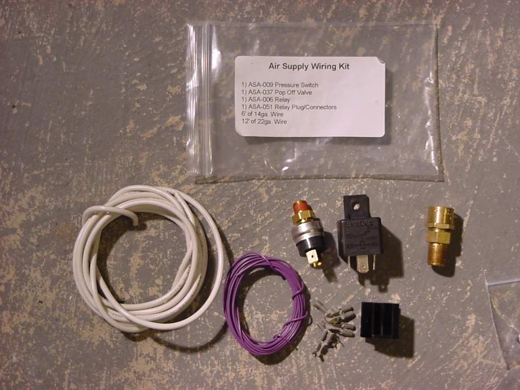
| Mounting
the Relay: |
There was a convenient hole drilled on the front side of the Auto
Computer Bracket. So I used another #8-32x3/4" Machine screw,
(2) #8washers and a #8-32 nylon lock nut to hold it in place.
You will need a phillips screwdriver and an 11/32"
Socket or Combo Wrench.
Note: The
relay allows for power from the battery to power the electric clutch
on the compressor. Otherwise you would have to run this power
through the switch and/or the pressure switch. |
 |
| |
| Installing
the In-Cab Air Gauge: |
| One
of the nice things to know is if you have enough pressure in your
system. Now since I like have reading close at hand I decided
to install a gauge in the cab so that I could see. |
 |
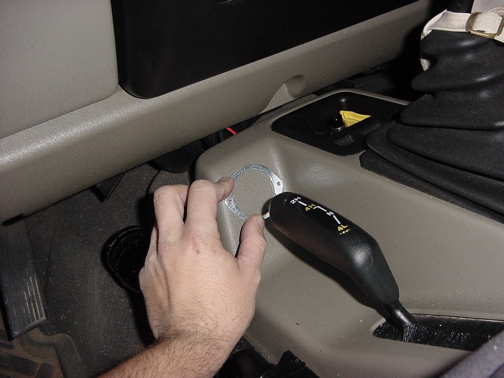
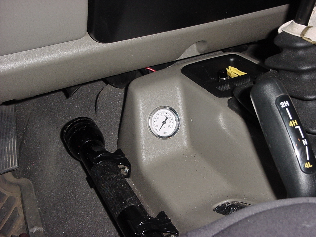
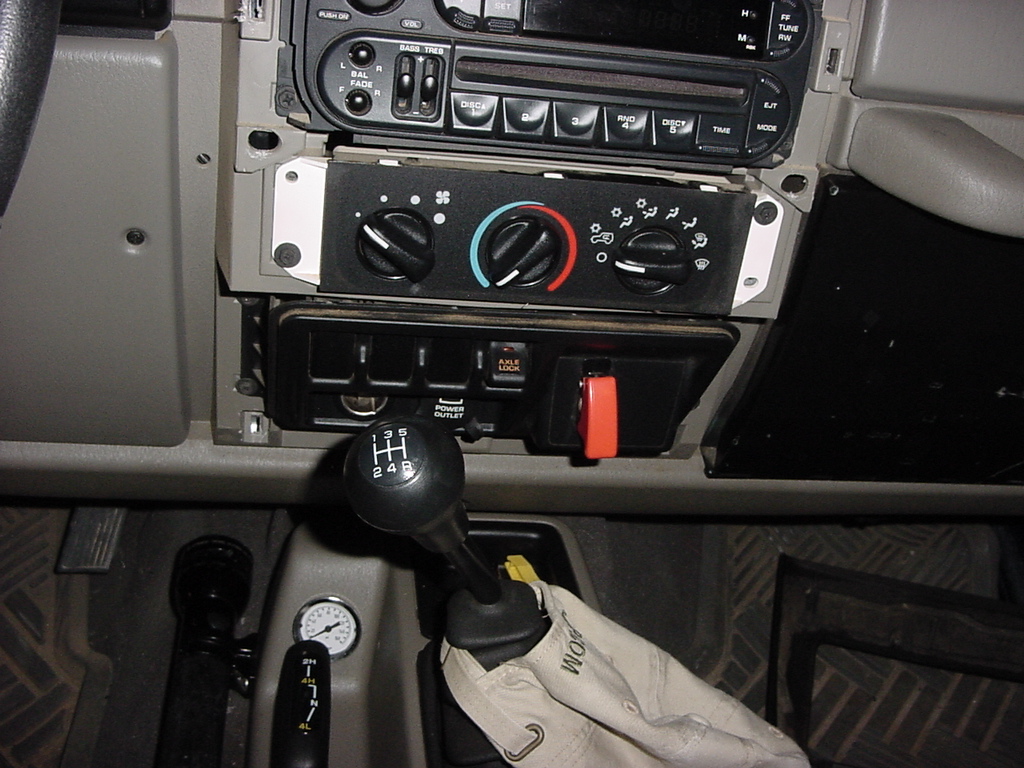
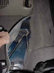
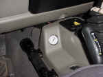
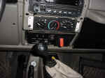
| There
is a convienent mounting location just in front of the 4wd shift lever.
It provides a good view of the gauge from the driver seat. I
used the backing plate for the gauge to mark my hole that I needed
to cut. Move the 4wd
shift lever to 4lo. |
 |
 |
| I
then connected the fitting to the back of the gauge. |
 |
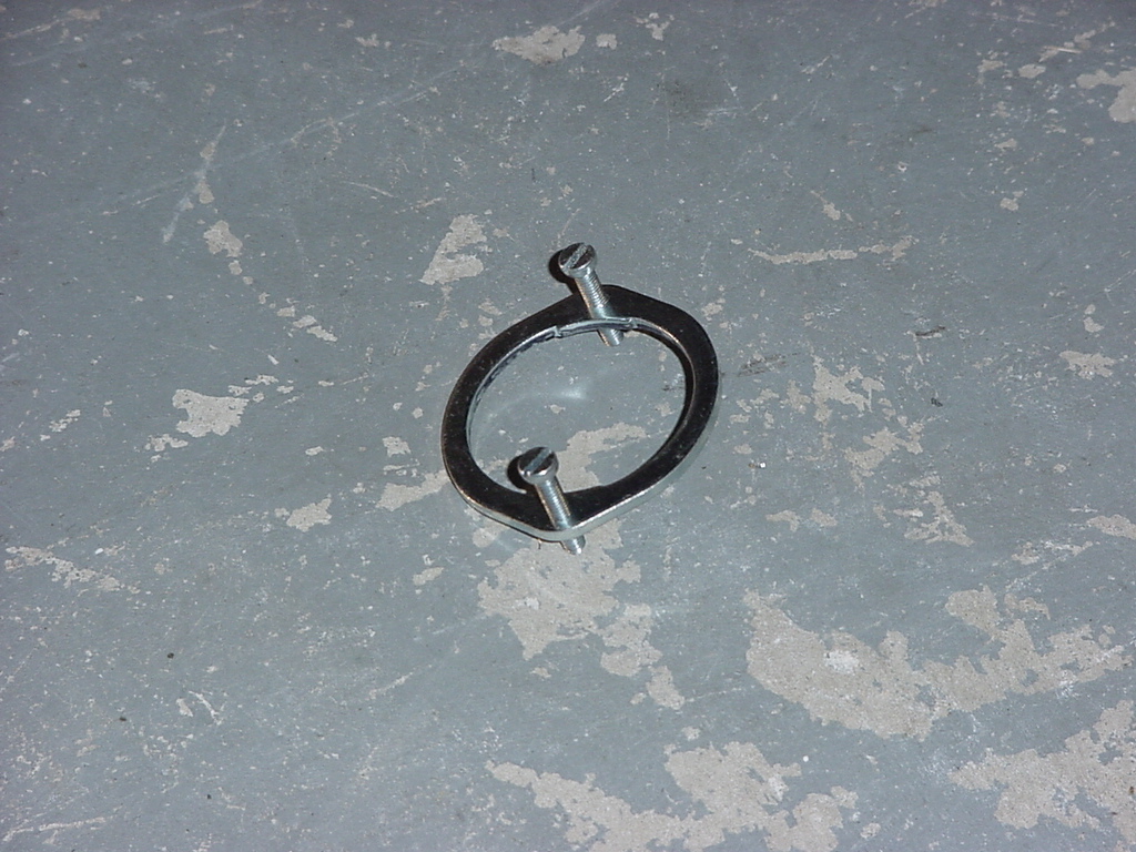
| Inserted
the screws into the back of the backing plate. These screws
will press against the backside of the plastic, so you need to cut
the hole just large enough for the gauge to fit in snuggly.
The plate goes over the back of the gauge and turns to lock in. |
 |
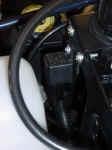
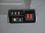
| Insert
gauge through the console, and lock the plate in from behind.
I was able to get to the screws with a stubby screwdriver. |
 |
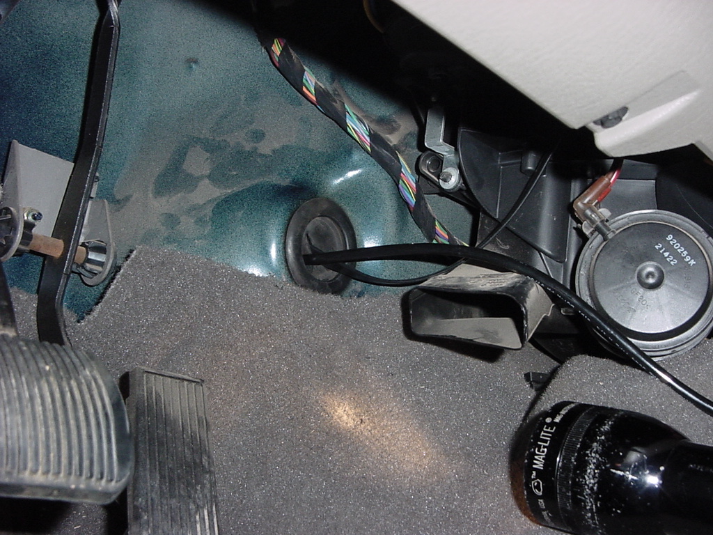
| I
pulled the firewall plug that sits behind the console and drilled
a small hole in it so that I could later route the air line from the
manifold to the gauge. |
 |
| |
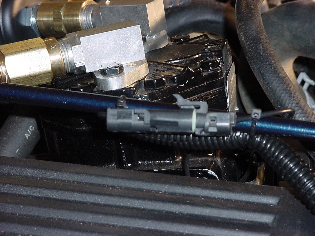
| Compressor
Power: |
| The
kilby's compressor came with a fitting on it to hook up electrical
power for the clutch. Now you could easily just cut this fitting
off and connect straight into the wire, but I liked the idea of being
able to disconnect the compressor if I needed to remove it.
So a quick trip to Pep-Boys netted me the other side of the connection.
I also wanted to be able to turn off the clutch just incase something
happened, like the pressure switch failing. So I also picked
up a safety switch. Normally these safety switch's are wired
so that you have to flip the cover to turn on the switch, but I wanted
to have it the opposite way, so all I did was file off the little
tang on the switch plate so that I could rotate it around. I
already had a switch for the locker override, so I put the compressor
switch right next to it. |
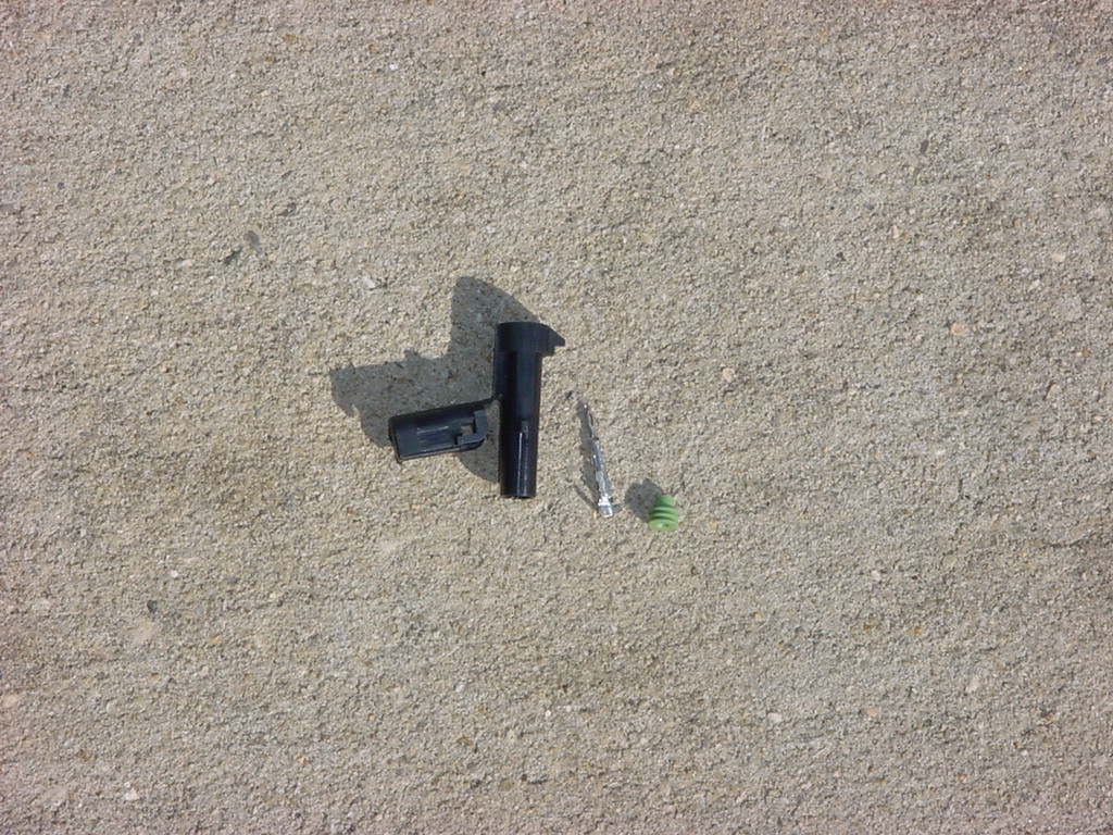
| The
GM connector parts. |
 |
| Insert
the rubber plug onto the wire, then crimp the end on to the wire.
Insert this into the plastic housing and close the end cover. |
 |
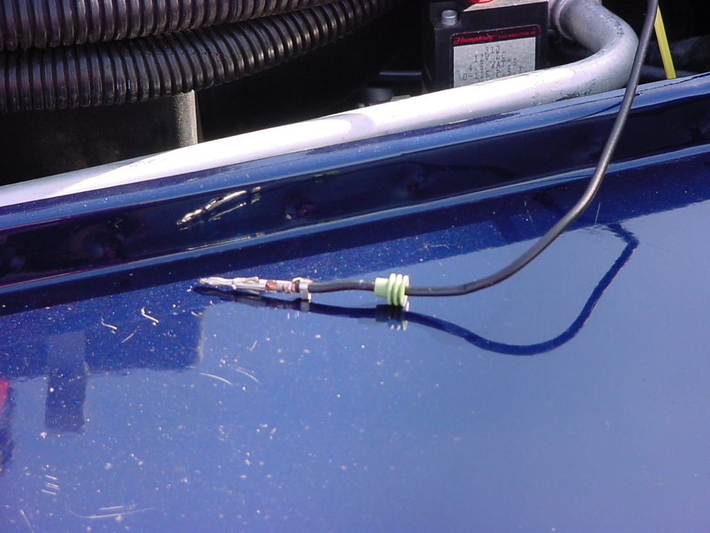
| Connect
the fittings together. This wire will run over to your relay. |
 |
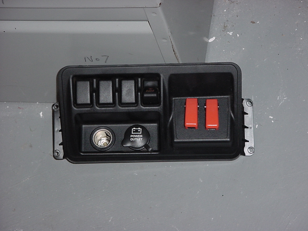
| Now
the simple thing of just taking apart your dash and installing the
switch. See Locker Override for details. The switch is
fed from switched power and feeds the pressure switch on the manifold. |
 |
 |
| |
| Now
that I had all the major parts installed, I could start routing my
air lines. Routing of the lines is fairly simple. Compressor
to oil filter, to manifold, to tank, to pressure regulator.
From the manifold you have 2 air chucks, 1 pressure gauge. |