The Rubicon came with lockers, but DC decided to add a little
bit of safety. So you can't engage them above 10 mph, at 45 mph
they disengage (45 in 4-low = scary), and you have to be in 4-low.
Well I didn't like this idea of having to be in 4-low to engage them.
I like my options. I don't think that I will need to use it anytime
in the near future, but since I had the parts I figured why not install
it. Now this installation just overrides the shifter position and
nothing else. So you still have the requirement of being under
10 mph to engage and they will automatically disengage at 45 mph.
Additional
Parts:
Wire
Wire end connectors
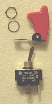
Safety switch (Pilot PL-SW26)
Tools
Needed:
Soldering Gun/ solder
small flat tip screwdriver
Phillips screwdriver
Drill
Installation:
First
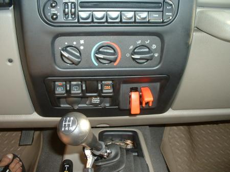
thing I did was figure out where I wanted to mount the switch.
A few others mounted it down by the 4wd shift lever, but since I
had my CB box in behind there I couldn't put it there. So
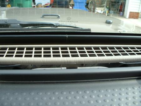
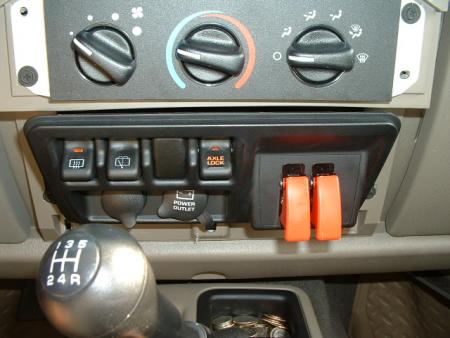
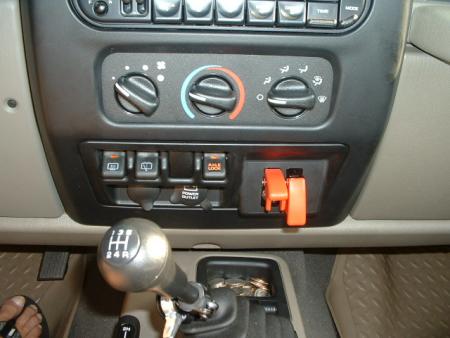
I looked at that flat spot on the dash where the air bad switch
goes on the 2003's. Close and convenient to the locker switch,
so I wouldn't need to run wires a long distance.
So
once again I disconnected the battery and slowly pulled up the defroster
panel.
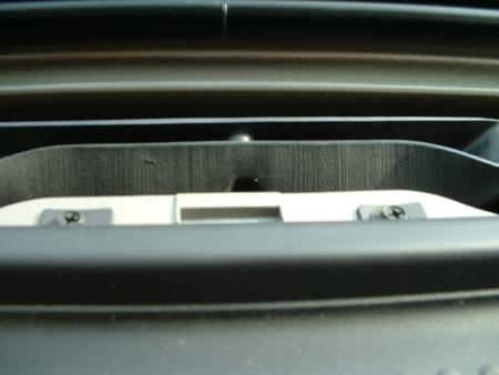
I
then removed the 2 center surround screws and pull off the center
dash surround.
Now
you will need to remove the switch panel. Unscrew the 4 screws
and pull it out.
I
found this switch at Autozone for $10. Now while it isn't
waterproof, I would be a little less concerned about the switch
if I was into water waist deep inside the Jeep.
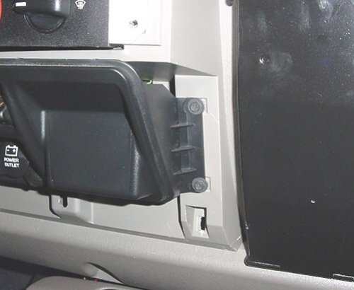
I
looked at the back of the flat area, and marked the position for
the switch and drilled the hole. After I got the switch mounted
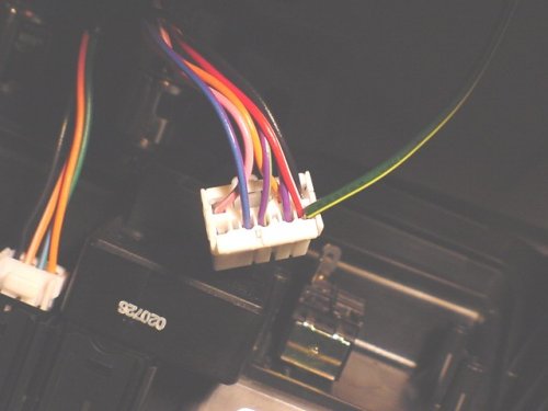
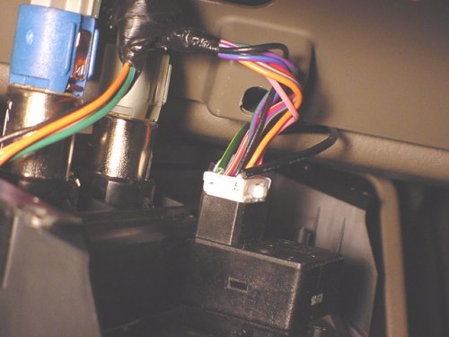
I turned my attention to the locker switch.
I already new that
I needed to ground the red and white wire to the black wire via
the override switch, but I didn't want to splice into the wires.
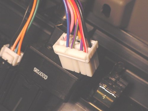
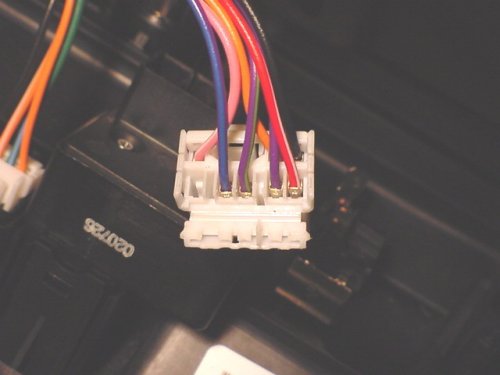
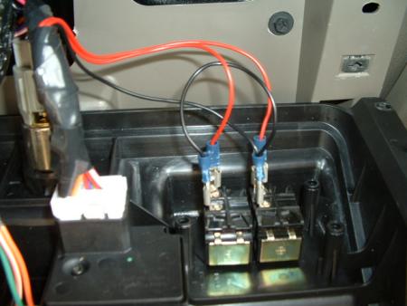
I carefully looked at the locker harness and saw that I could open
it up with a small screwdriver. Once I got the harness open
I could see that there was enough room to insert a wire down along
the original wires next to the metal connector. This would
give me good contact and not damage any wires. I carefully
installed connectors on the ends of 2 wires and then stripped and
soldered the ends of the others. I gave it just a light solder
to allow the wires to flatten out so that I could install them.
I was able to put the wires in to the harness without this step.
Close the harness back up after you get the wires down inside.
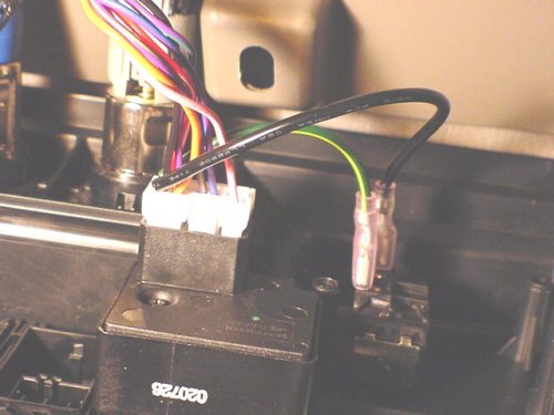
The
great thing is 4 yanks and the only thing left is a switch.
No signs that wires were ever installed. Now once you have
everything hooked up, time to test. I did this in my garage,
(open the door). Start it up, flip the switch and hit the
lockers. It was nice to see the lockers come on in 2wd.
Okay turn everything back off and put it all back together.
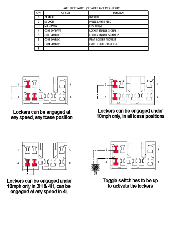
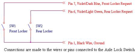
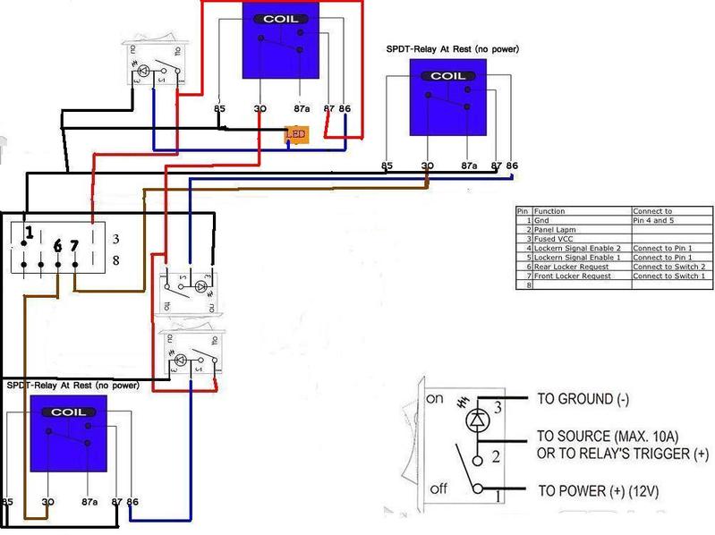
Here is a diagram showing the other ways to wire in this switch. I
don't take credit for this diagram.
After having this installed for a few months, I still haven't
used it. I like having the option. I will be moving the switch when
I install my power converter. I will probably place it down by the 4wd
shift lever like a few others.
Independent Locker Control by Ken White (used
with permission)
Independent control of the Front and Rear
Lockers is accomplished by adding 2 Single Pole, Single Throw (SPST) switches,
some jumper wires, and connectors to the existing Axle Lock Switch and/or wiring
located in the center console.
As with most electrical installations, the first thing that should be done is to
disconnect the battery’s negative terminal connection from the battery.
Inside the TJ’s cockpit, gently pull back and up on the defroster ventilation
panel located between the windshield and dash. It should easily unsnap without
much effort.
Once the vent is out of the way, you will
see two �” Hex/Phillips head screws located on the top of the center console.
Remove these and then gently pull the center console facade straight out and
upward – it is held in place by 4 spring clips so hold the top and bottom when
performing this task.
Once the console facade has been removed, remove the four �” Hex/Phillips
head screws holding the switch panel in place. Pull the switch panel out and you
will now have access to the connections needed to accomplish this modification.
The schematic shows the electrical connections that need to be made for this
modification. The switches I used are from AutoZone. The manufacturer is Pilot,
the P/N is PL-SW26, and the type is Racing Switch with Safety Cover – about
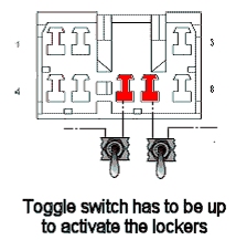
$10.00 each. I put both switches in the vacant Passenger Air Bag On/Off switch
area.
Connect a jumper wire from Pin 1, or the BK Wire, located on the back of the
Axle Lock Switch to the same contact on both switches. Then connect a jumper
wire from the other contact on the Front Locker Switch to Pin 7, or the VT/DB
Wire. The remaining Switch will control the Rear Locker, so connect a jumper
wire from the remaining switch contact to Pin 6, or VT/LG wire. This completes
the modification.
Connect the negative battery terminal back to the battery and test. Insert the
key into the ignition and turn on one of the switches. You should hear the pump
engage and then turn off as well as well see the dash indicator light flashing
or in steady on state. Turn the switch off and the light should extinguish. Test
the other switch. If everything looks good, put everything back together in the
reverse of taking it apart.
Rear Engage
Rear Indication
Front Engage
Front Indication
Theory of Operation
(See section 8W-31-12, 13, 14, and 15, and 8W-80-5 of the FSM)
Since the Relays always have power
applied to the D4 and D13 connection, applying a ground to D6 or D11 will
cause the Rear and Front Locker Relay to energize, respectively. Once
energized, voltage will be supplied to the Rear or Front Locker Pumps.
They will turn on until 5 PSI of pressure is achieved, and then the pump
will turn off – assuming no air leaks.
The two switches basically bypass the existing Axle Lock Switch and control
the Front and Rear Locker Relays independently, as well as sending a Logic
“0” to the Instrument Cluster (EMIC). The Front and Rear Locker Indicator
lamps function exactly the same as originally designed: slow flashing
when lockers are engaged without the axles actually being locked, and
steady on when the lockers are fully locked and have sent an additional
ground signal to the EMIC.
Two important things to recognize about this modification:
1. The switches bypass all safety interlocks, so the lockers can be engaged
at any speed, and in any transfer case setting, and will almost certainly
not disengage when going over 45 mph.
2. The Locker Relays always have voltage applied to them, even when the
key is out, so the switches must be returned to the open position when
not in use. If not returned to the Off position, then there is a possibly
of running the battery down if there is a leak in the air lines and the
pumps continue to cycle, and/or damaging the pumps.
This modification is performed at your own risk, and I in no way assume
any responsibility if you break your drive train using this modification
foolishly.
Now that all that legal junk has been said, this modification works well
and allows great flexibility when playing!
Ken
Independent Locker Control LED Diagram by Greg Donohoe (used
with permission)
Greg worked out this trick LED setup for the independent locker control.