I was looking for a little more air for the engine. The JK's seem to have a slight power lag around 2,000 rpm's. If you look at the intake for the JK's it is a little restrictive at the start. I also wanted an air filter that was easy to clean and would last a long time. I wasn't to concerned with horsepower and torque gains at the high end of the rpm's. I had dealt with the oiled filters in the past, and have heard of warranty claims being denied because of oil on the sensors from these filters. AEM's filter is a dry filter, so no oil to give it this possibility. Though a custom intake in itself could raise issues with DC. Here is some information borrowed straight from AEM's web site if your interested in what they say about their intake..
I looked at allot of different intakes, including fabing my own system. I decided that the dry filter was the deciding factor and went with the AEM. A quick call to Mike at 4x4rockshop and a system was on the way. Actually I should be more descriptive. The quick call was about 30 minutes.
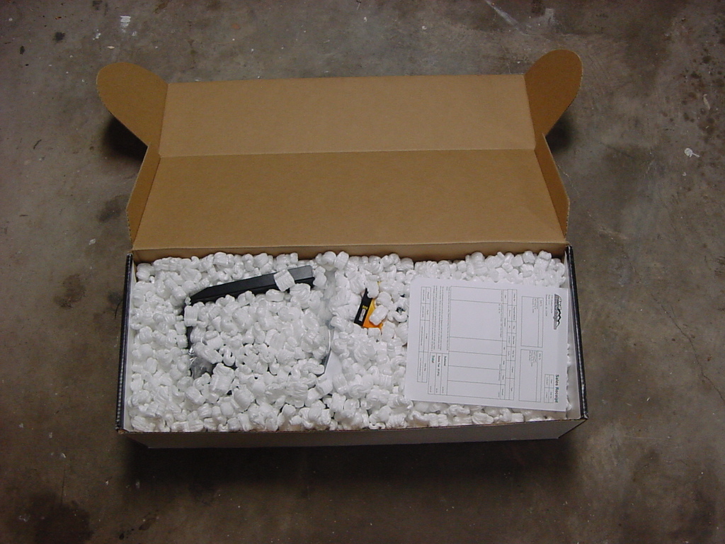
| The Parts: |
| Be careful opening up the box. It can be messy and if you got it from Mike their might be a few other surprises in it. |
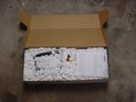 |
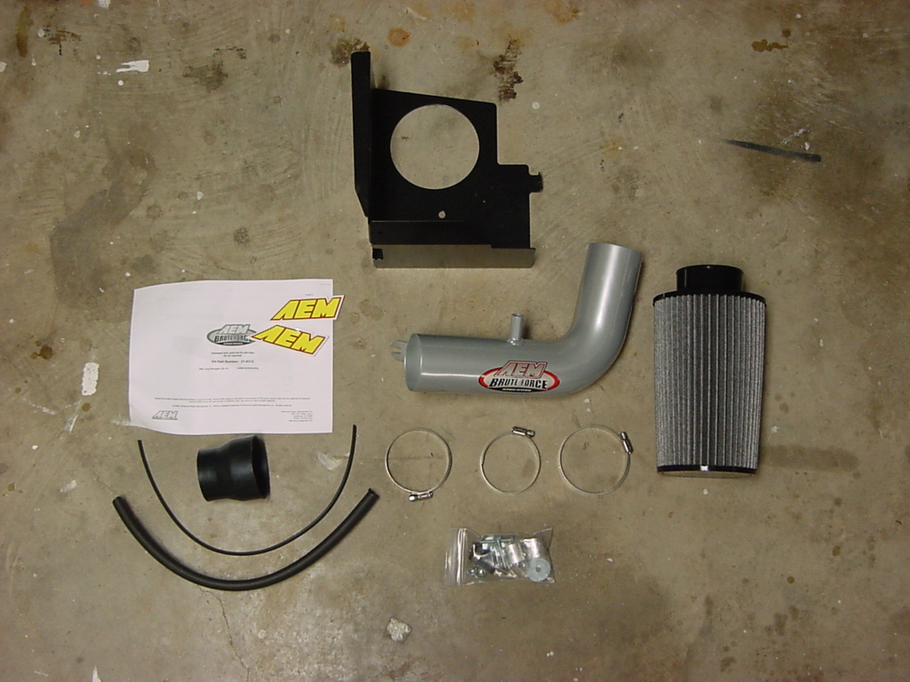
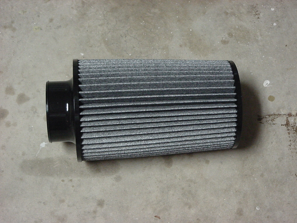
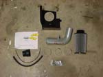
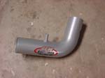
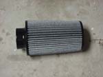
| Here is what you get in the kit. The packaging was nice and I really didn't have to clean out to many pieces of the packing from the intake tube. Take a good look into the tube and filter just to make certain that nothing is there that can cause you an engine problem. |
 |
| |
| Installation: |
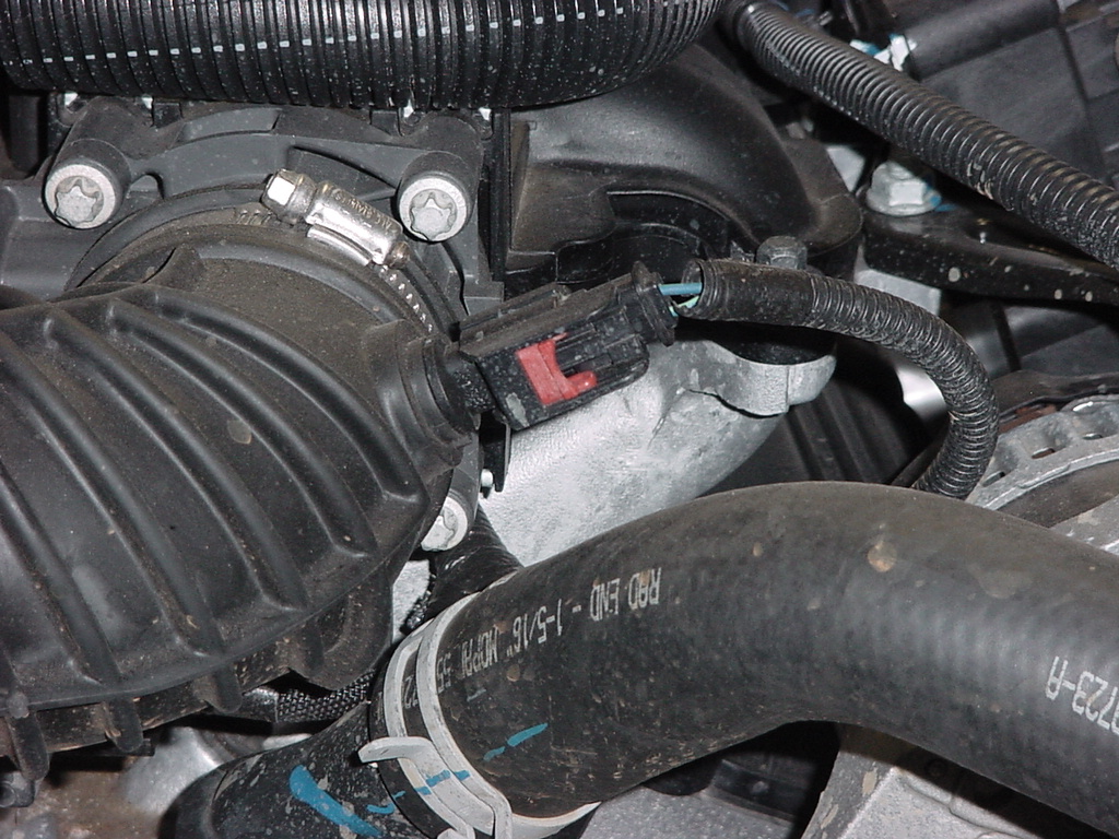
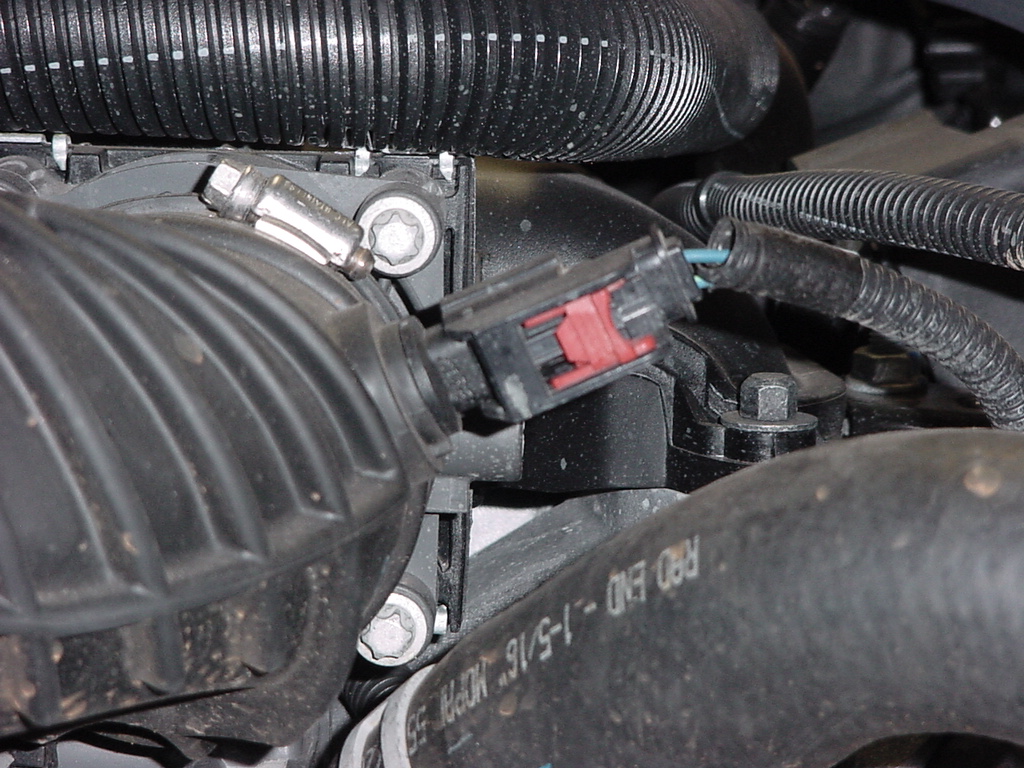
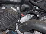
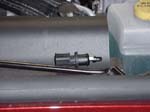
| 1. Remove the lead from the Inlet Air Temperature (IAT) Sensor. You will need to pull this red clip up first before you press down on the tab above it to release the connector. Be careful you do not want to break this piece. |
 |
 |
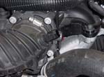 |
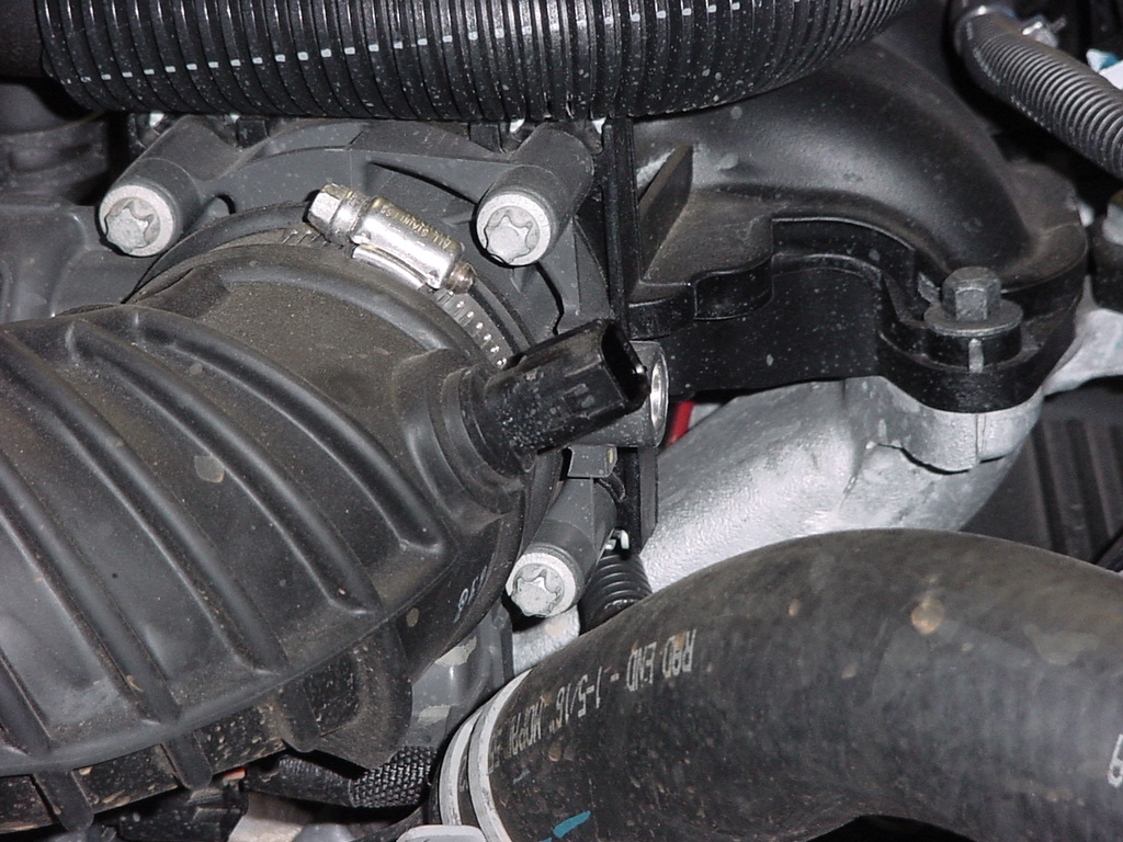
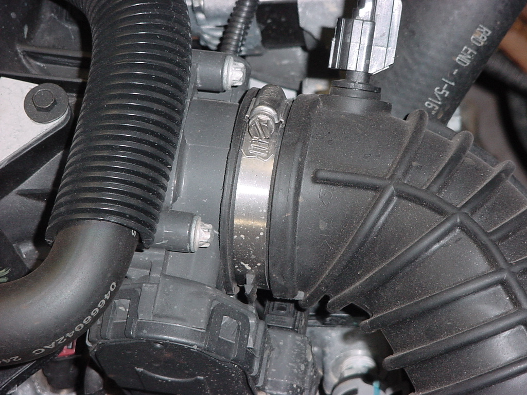
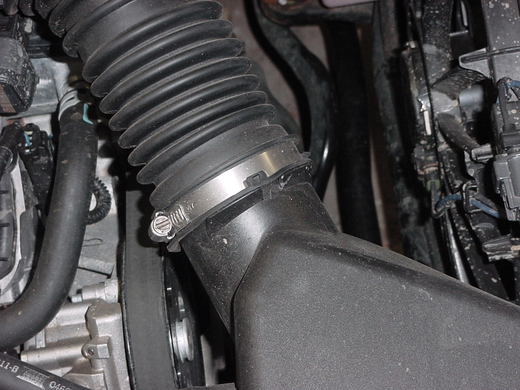
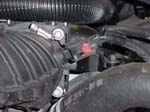
2. Remove the air inlet hose. Loosen the band clamps at both ends of the air tube with a 5/32" socket. You can just pull the tube off. Be careful the throttle body is plastic.
Note: You can remove the IAT sensor from the hose with the hose installed on the vehicle. I tried it both ways, neither was any harder to get the sensor out. |
 |
 |
 |
 |
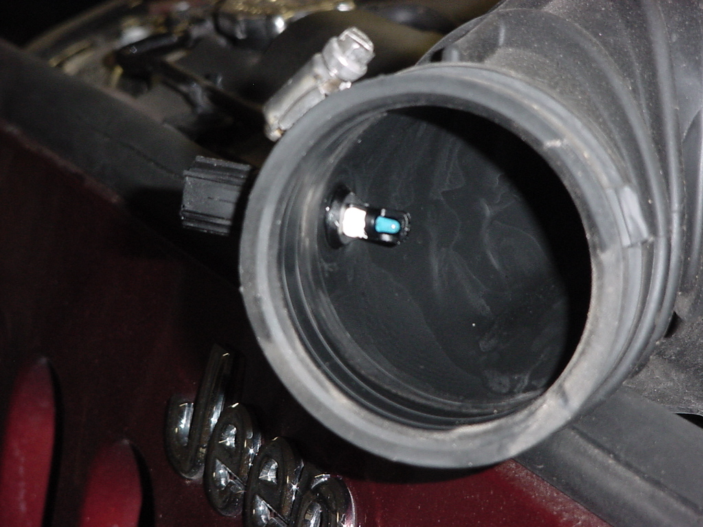
| 3. Remove the IAT sensor from the air inlet tube. This has a small lip that engages the inside of the air tube. I just wiggled it side to side and up and down until I was able to get it to come out. As you can see from the inside picture the tip is easy to break, but you don't need a lot of force to get it out. |
 |
 |
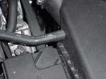
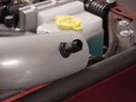
| 4. Remove the crankcase breather hose from the air filter box. Just give it a slight twist to break the seal and pull off. Once again this doesn't take much pressure. |
 |
 |
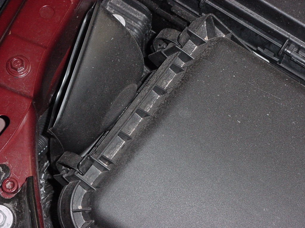
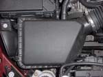
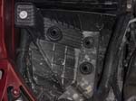
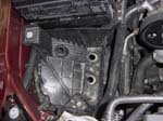
| 5. Remove the filter box. There are 2 ways to do this. I was able to just grab the whole box and pop it free from the grommets below. This may work for you. Otherwise. Release the 4 clips that hold the filter cover on and remove the top. |
 |
 |
 |
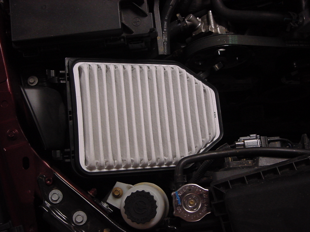
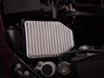
| 6. Remove the air filter. On an interesting note, you can put this filter in either way, so if you remove it for some reason, make certain you remember or mark which side was the dirty side. Not a good idea to reinstall an air filter with all the debris collected now pointing down stream towards your engine, slightly defeats the purpose of an air filter. |
 |
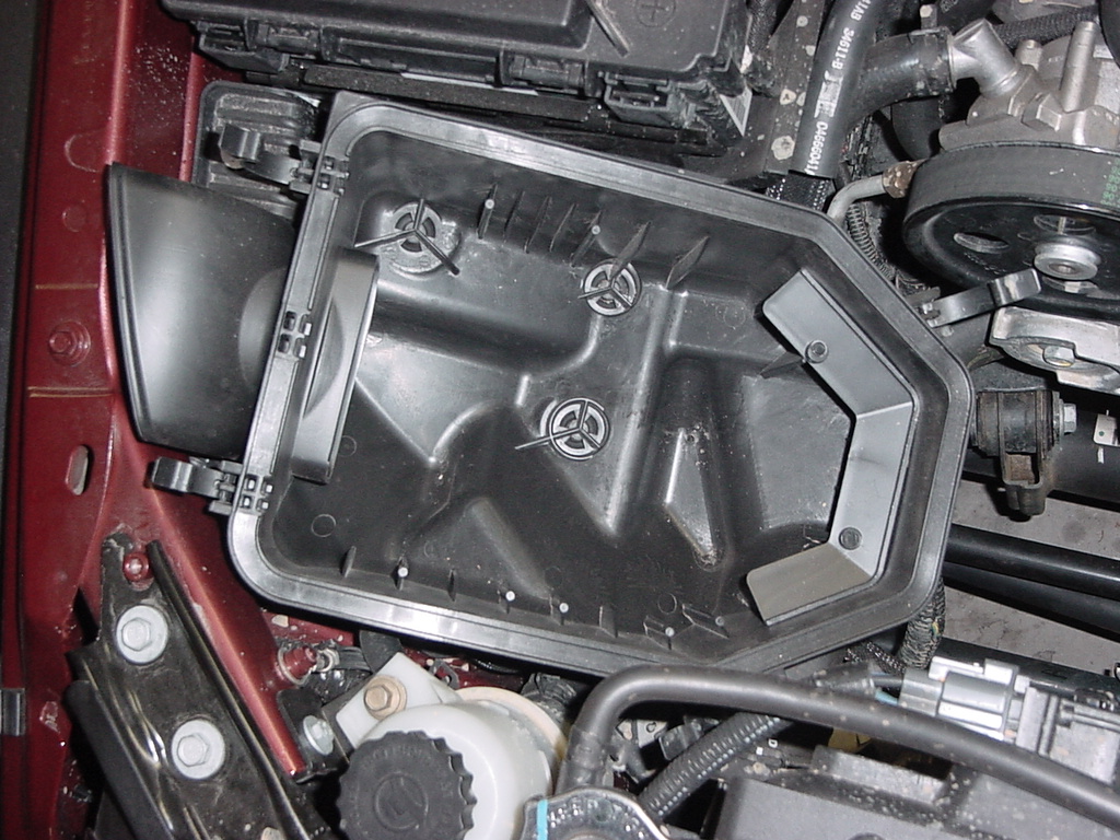
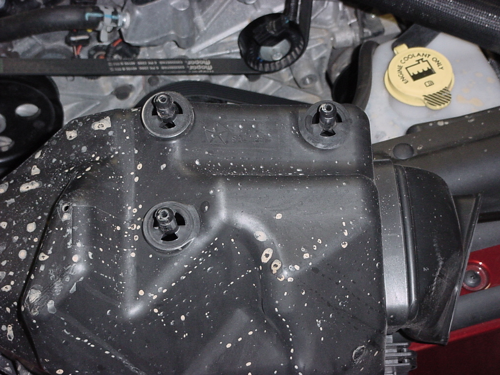
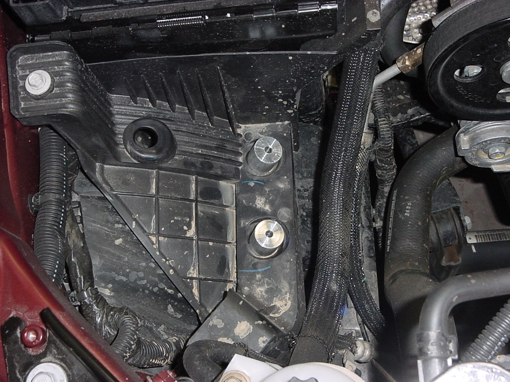
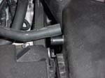
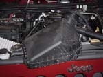
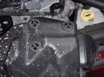
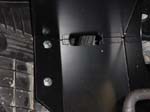
| 7. Remove the base of the Air filter box. The 3 prongs that hold it in are located at what looks like radiation symbols in the first picture. Just pull up as you wiggle the box back and forth the prongs will release from the grommets underneath. |
 |
 |
 |
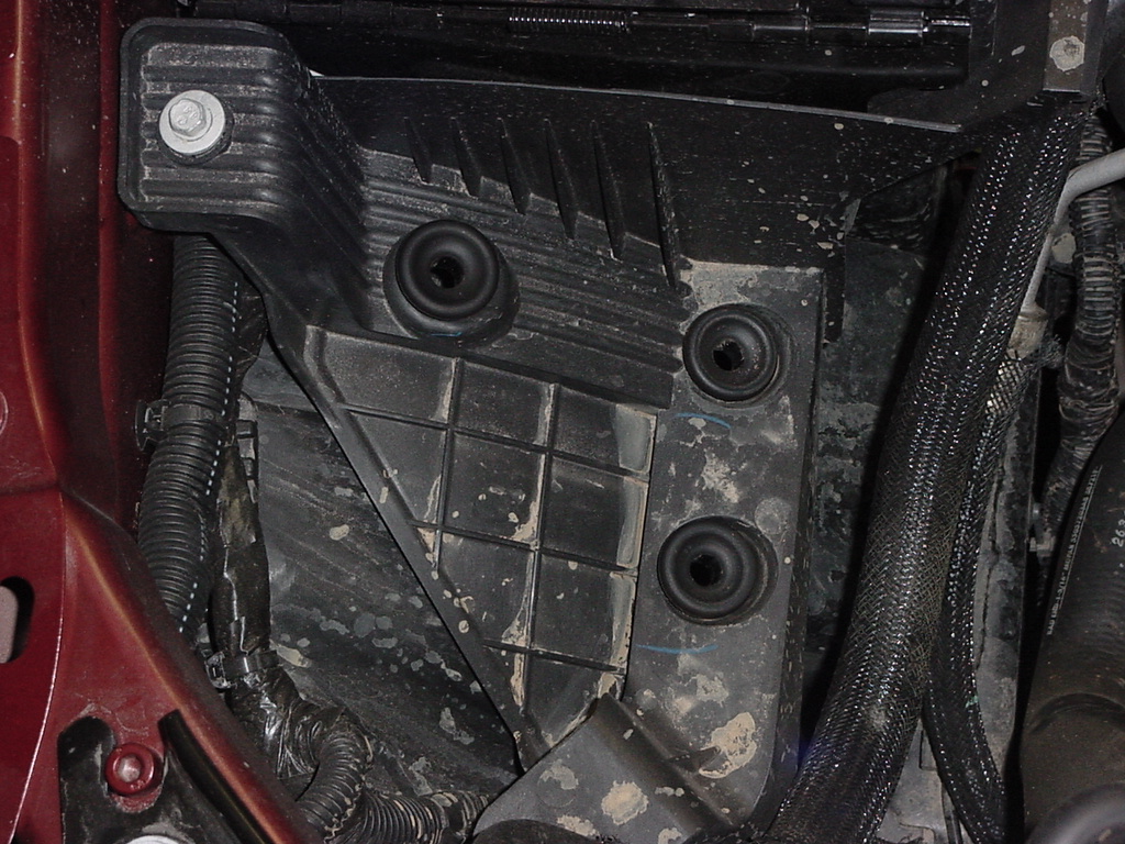
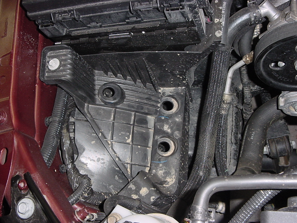
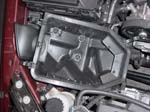
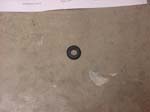
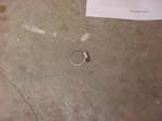
| 8. Remove the three grommets from the base support. I was able to pull two of them out by hand, but the third requires grabbing it with a pair of pliers. |
|
 |
 |
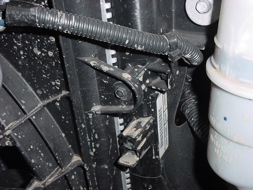
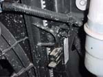
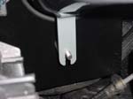
| 9. Remove the self tapping screw securing the ran shroud to the radiator with a 5/32" socket. You will reuse this screw to mount the heat shield, so try not to lose it. |
 |
| Note: When installing the AEM intake, leave everything loose fit until you read to tighten it. Some alignment and fitment of parts will require you to adjust positioning of parts. |
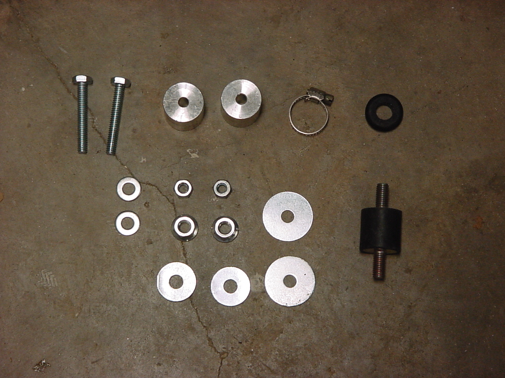
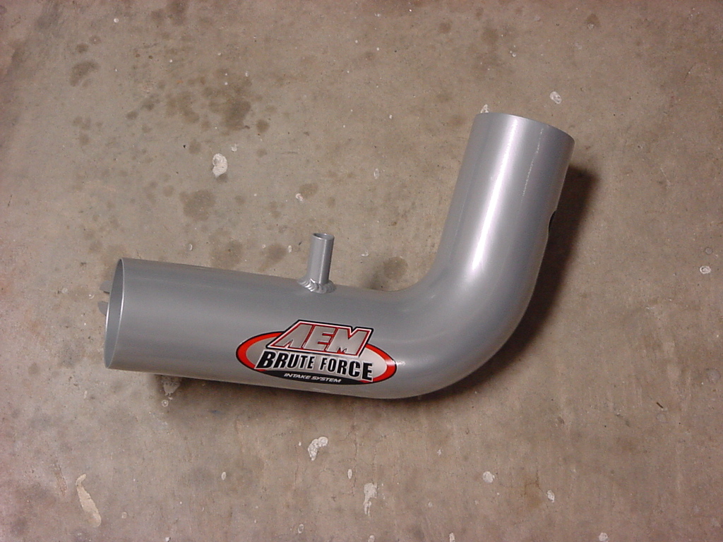
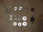
| 10. Open up the parts bag without sending the parts scattering across the garage. This is what you should have, just in case that happens to you, also. |
 |
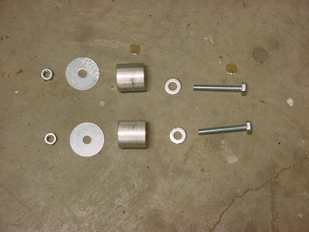
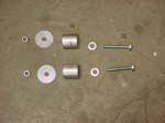
| 11. Here is what you need to pull out of the bag to install the heat shield. |
 |
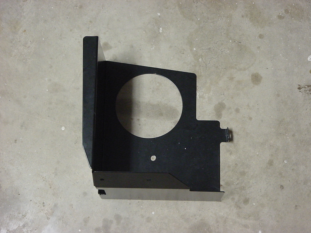
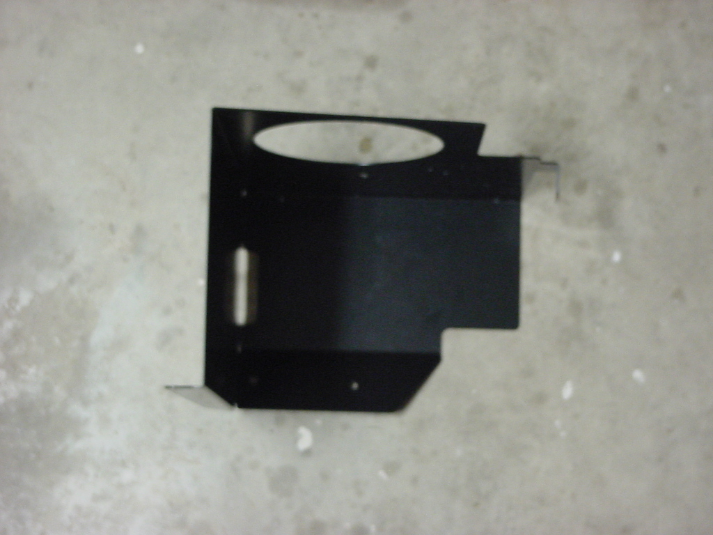
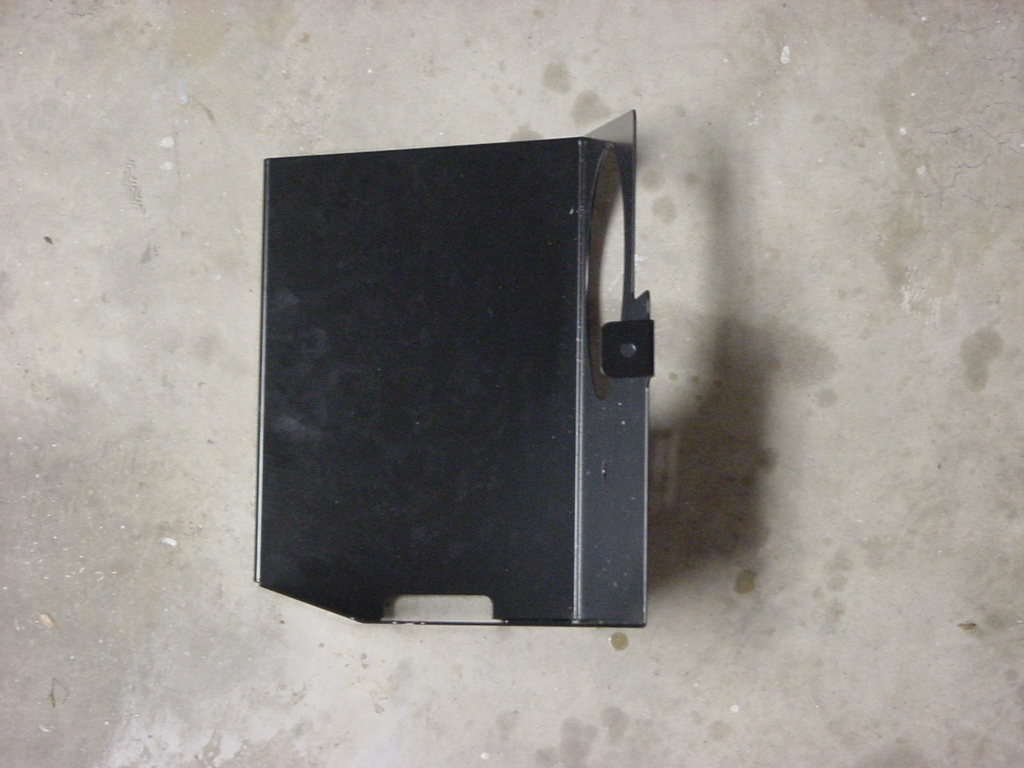
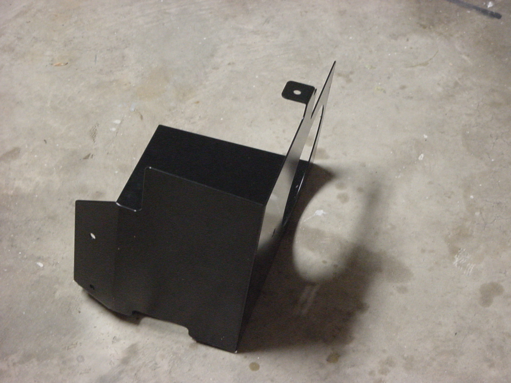
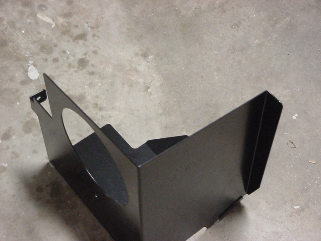
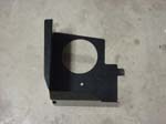
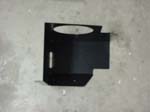
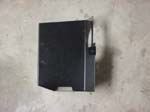
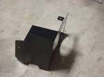
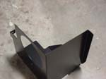
| 12. Here is a few different pictures of the heat shield. |
 |
 |
 |
 |
 |
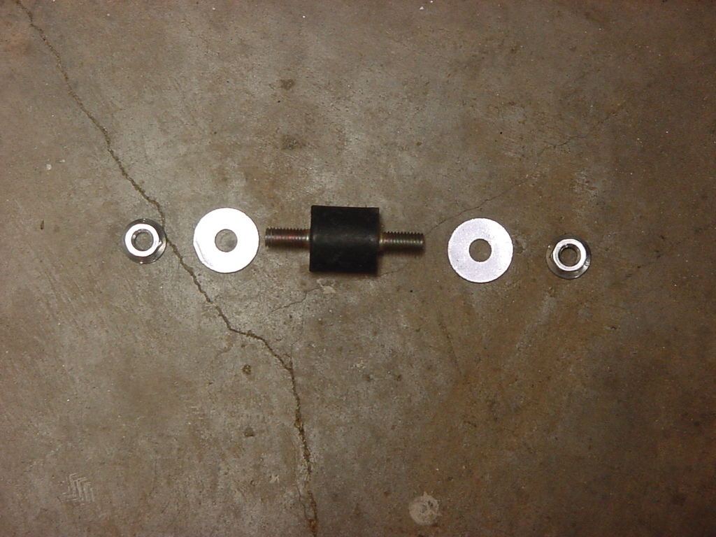
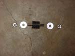
| 13. Place the two supplied spacers in the same location as the bottom stock grommets that you removed. |
 |
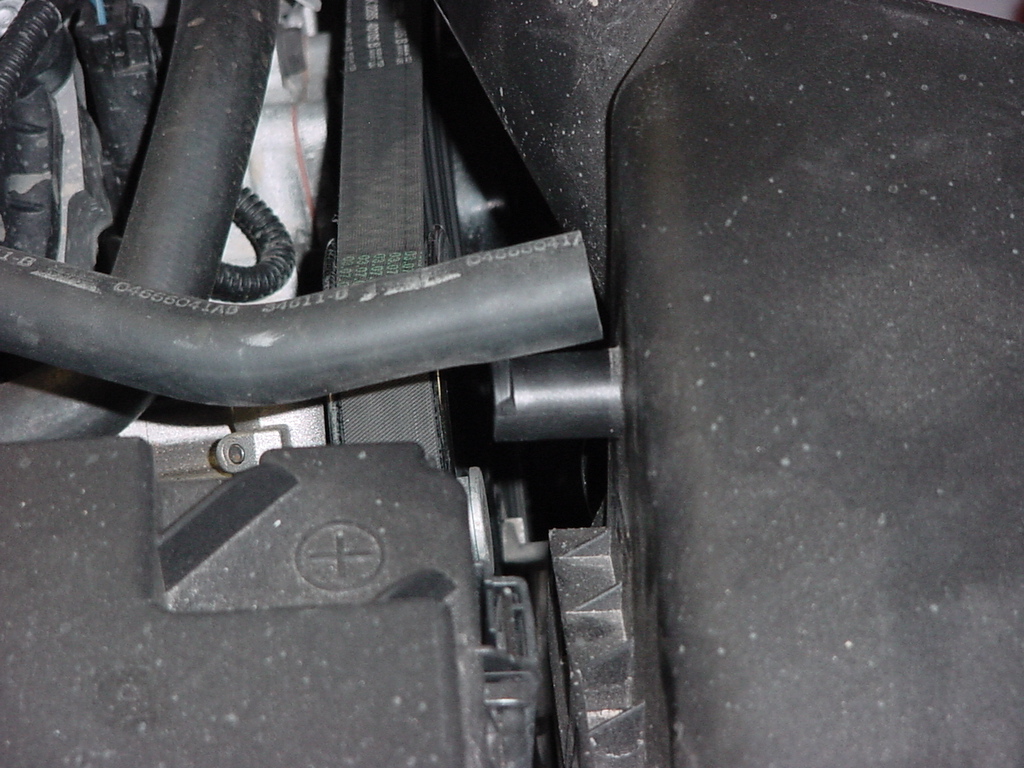
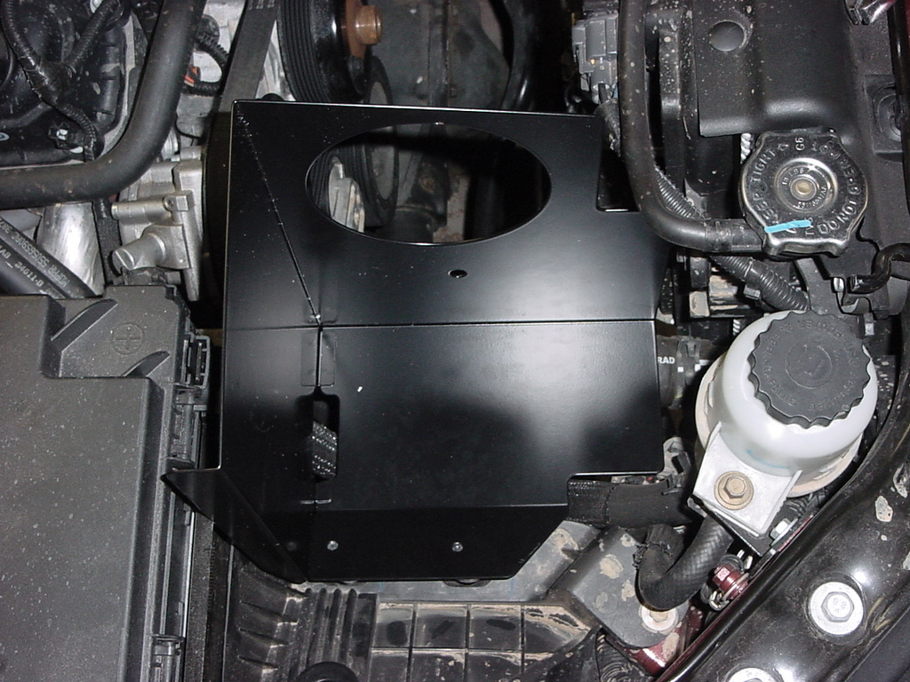
| 14. Place the two small washers over the bolts and insert them into the heat shield. Slide the heat shield between the fan shroud and the fuse box guiding the bolts into the spacers. |
 |
 |
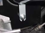
| 15. Reinstall the self tapping screw through the heat shield and into the fan shroud support. Do not tighten yet. This will hold the heat shield in position while you install the nuts below the heat shield. |
 |
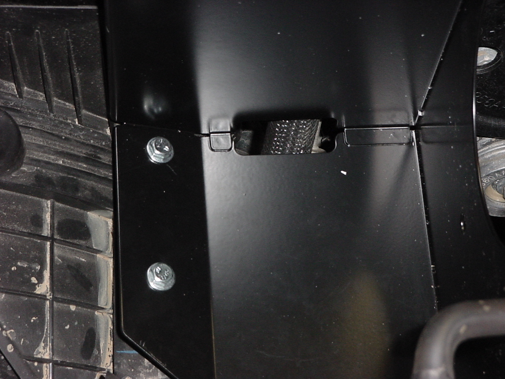
| 16. Install the fender washers and nuts below the heat shield. You will be reaching blind underneath here, so you will have to do this by feel at the same time that you hold down the bolts from above. Tighten the bolts and nuts with a 7/16" Socket and Combo wrench, then tighten the self tapping screw with a 5/32" socket. |
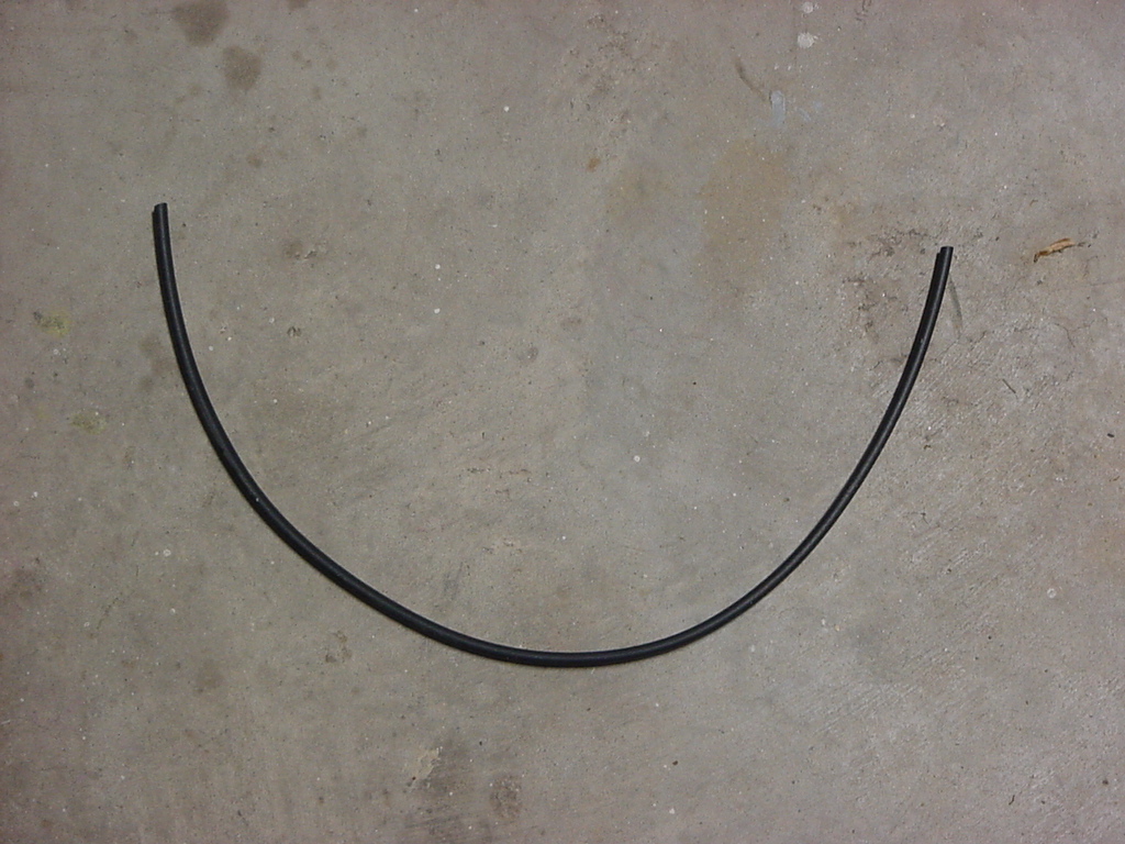
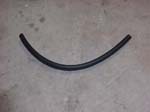
| 17. Install the rubber edge trim and the rubber gasket on the heat shield. You will need to cut the rubber gasket to fit around the corners with a metal shears. The rubber edge trim can be cut with a scissors. |

Rubber edge trim
|
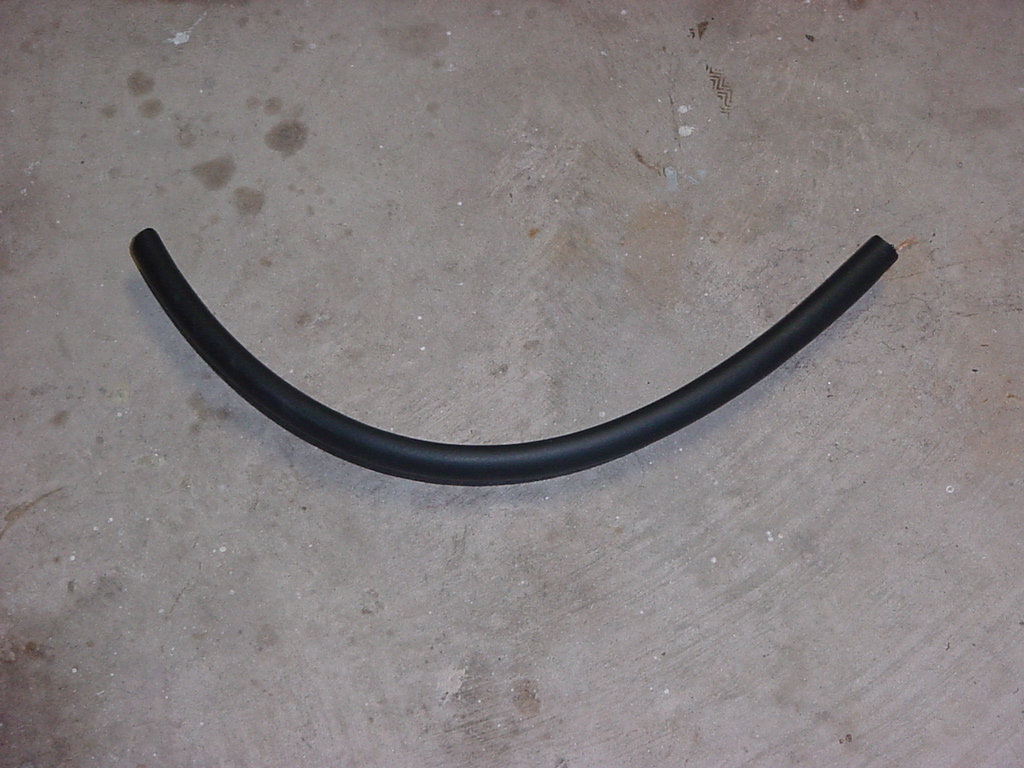
Rubber gasket
|
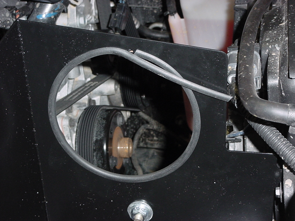
| 18. Line the pipe opening with the rubber edge trim, cut to length. I used the left over piece on the side where the radiator coolant bottle lines run. |
 |
 |
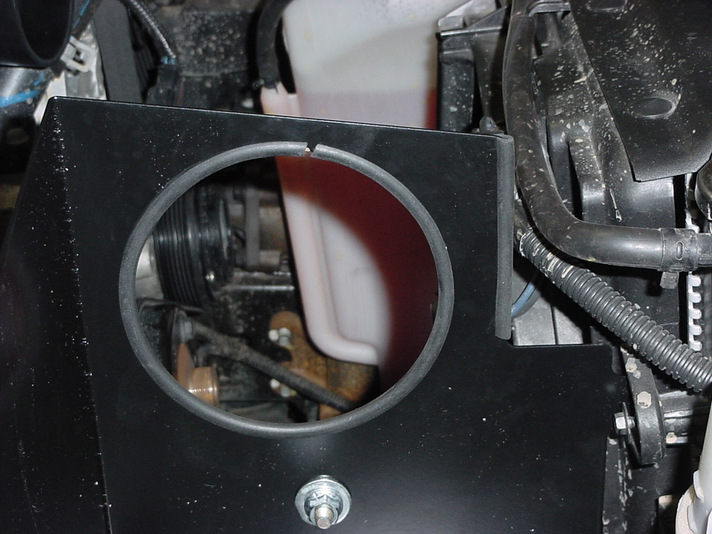
| 19. Cut the rubber gasket to fit along the top edge of the heat shield. I recommend starting at the point by the fuse box and working your way around the top. I just left the extra hanging out. I will check to see if this is causing any issues in a while. |
 |
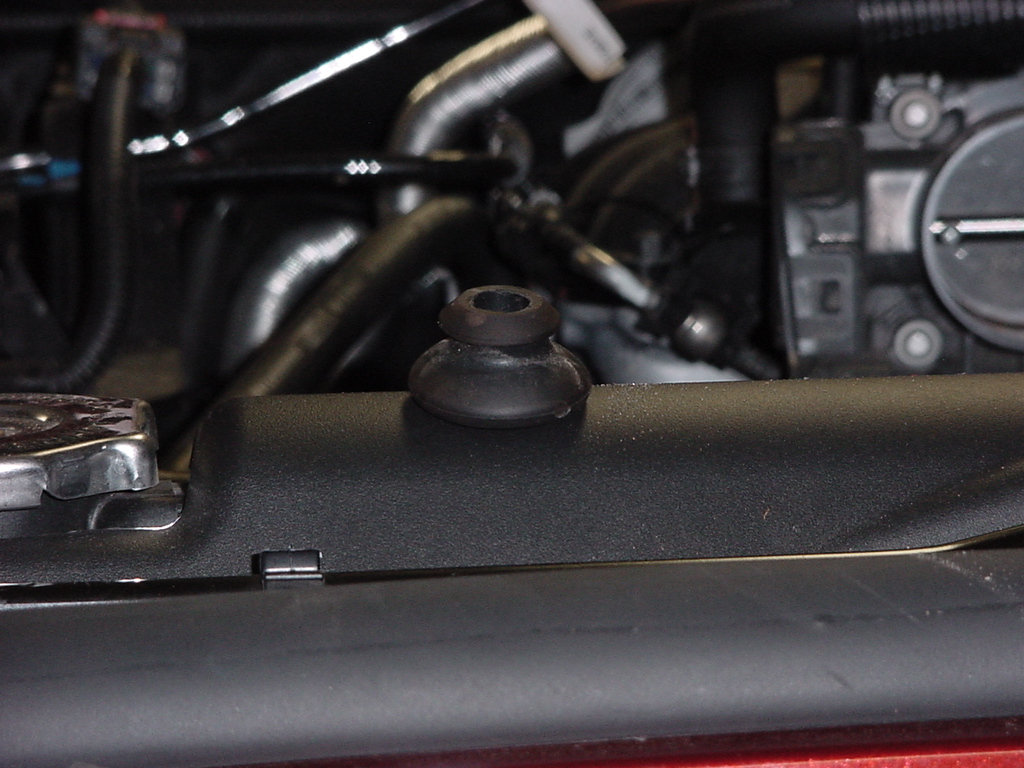
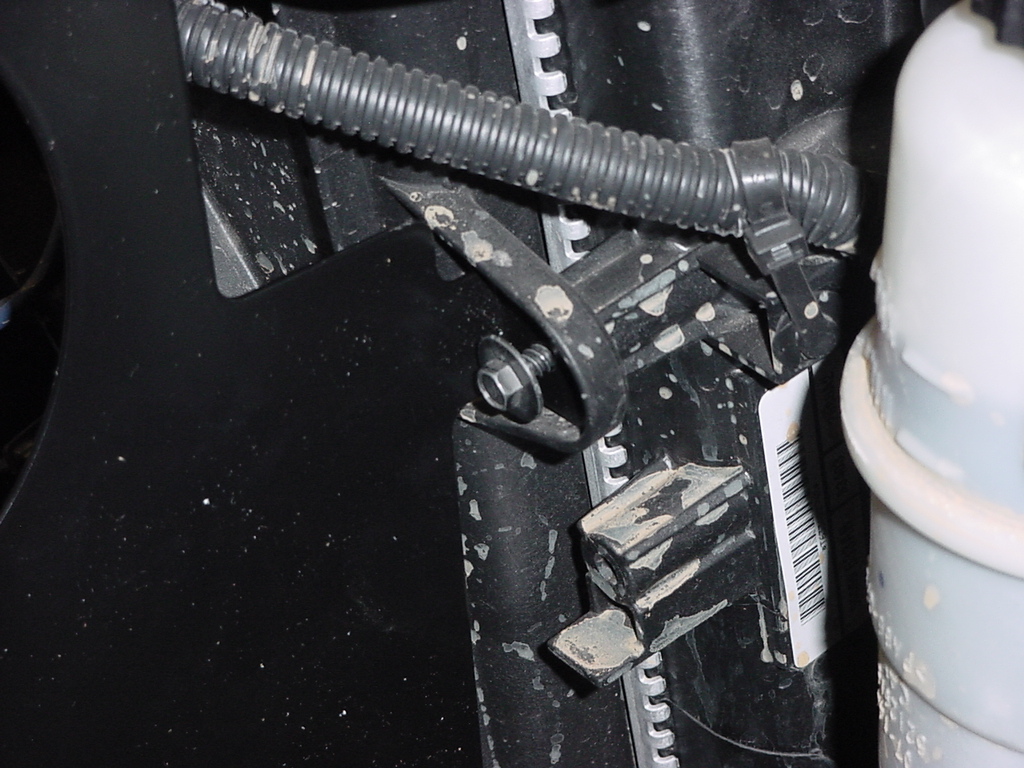
| 20. Install the rubber mount to the heat shield. Insert one end of the mount through the heat shield and secure with the washer and nut. Tighten with a 1/2" Socket. |
 |
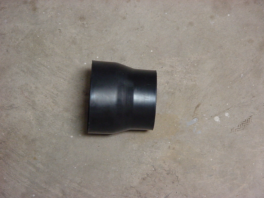
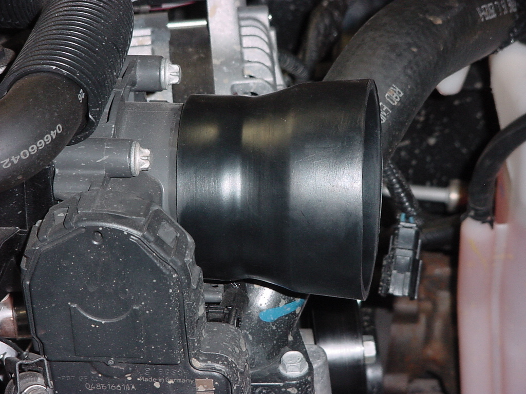
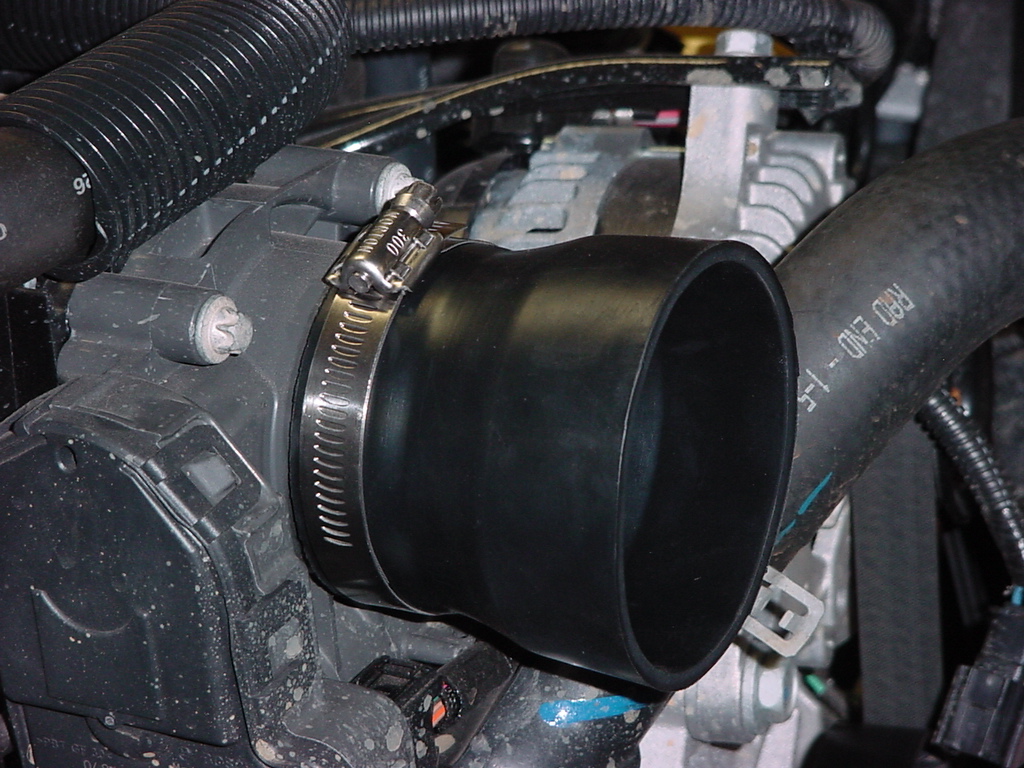
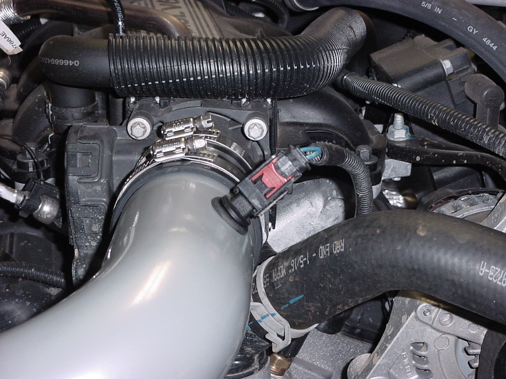
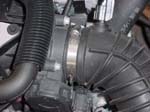
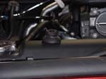
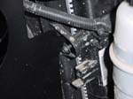
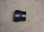
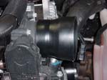
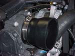
| 21. Install the rubber reducing coupling over the throttle body. This is a very tight fit, so will require some work to get it over the throttle body mouth. It is best to work it over from the inside. Patients on this, remember the throttle body is plastic. |
 |
 |
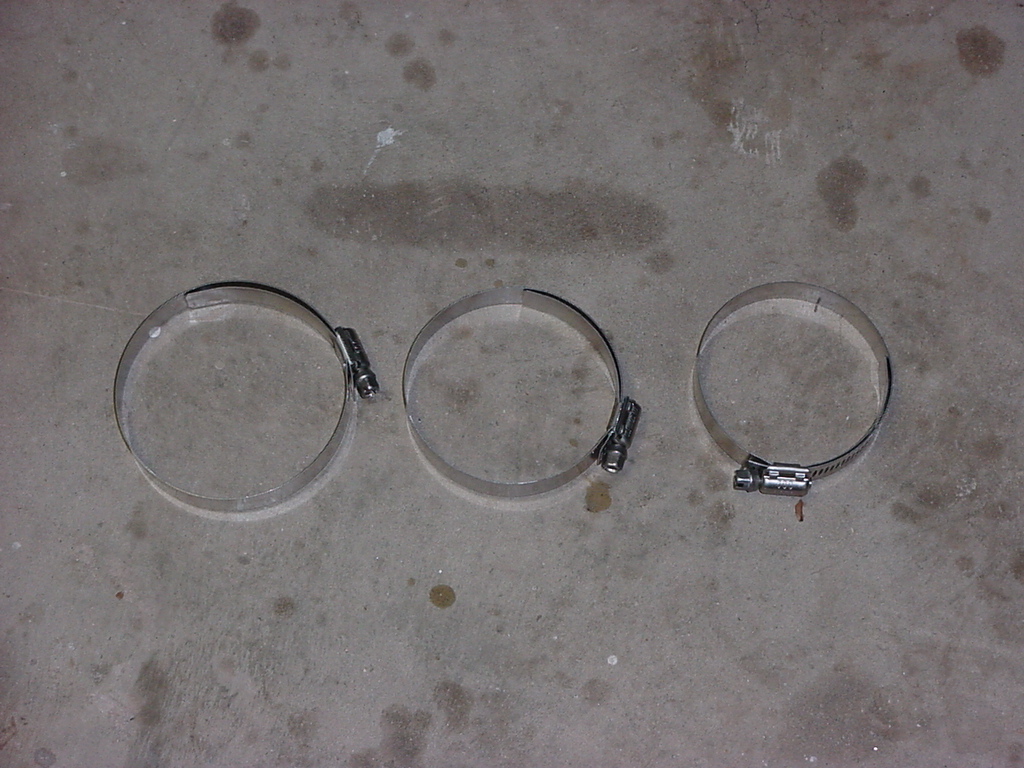
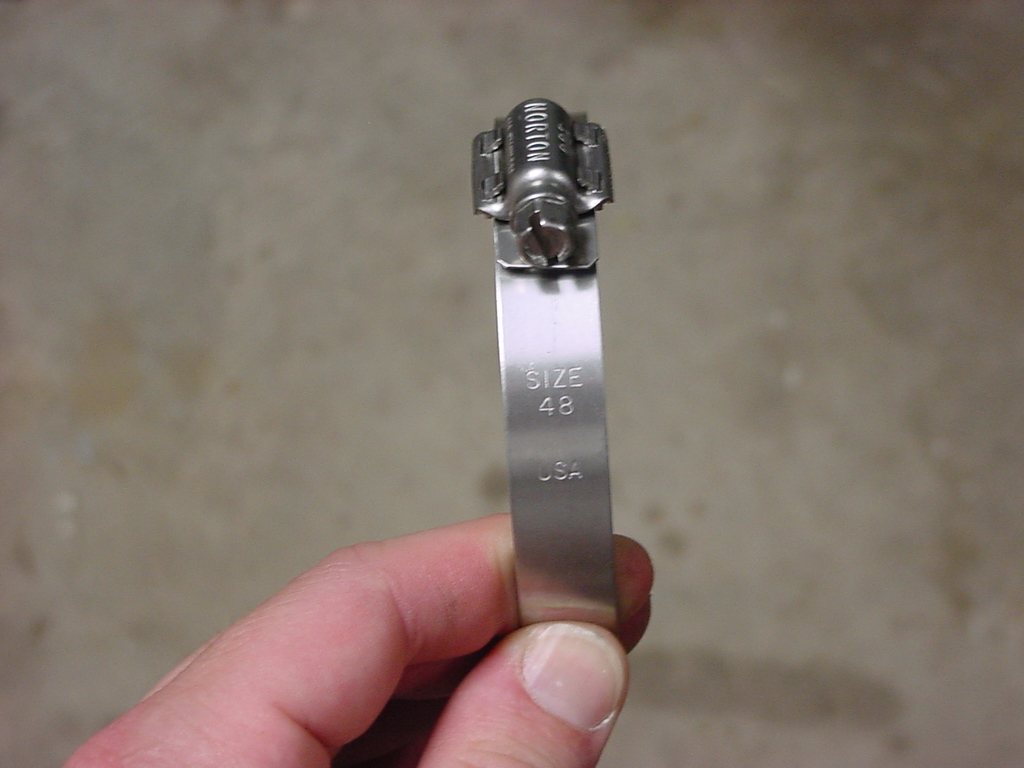
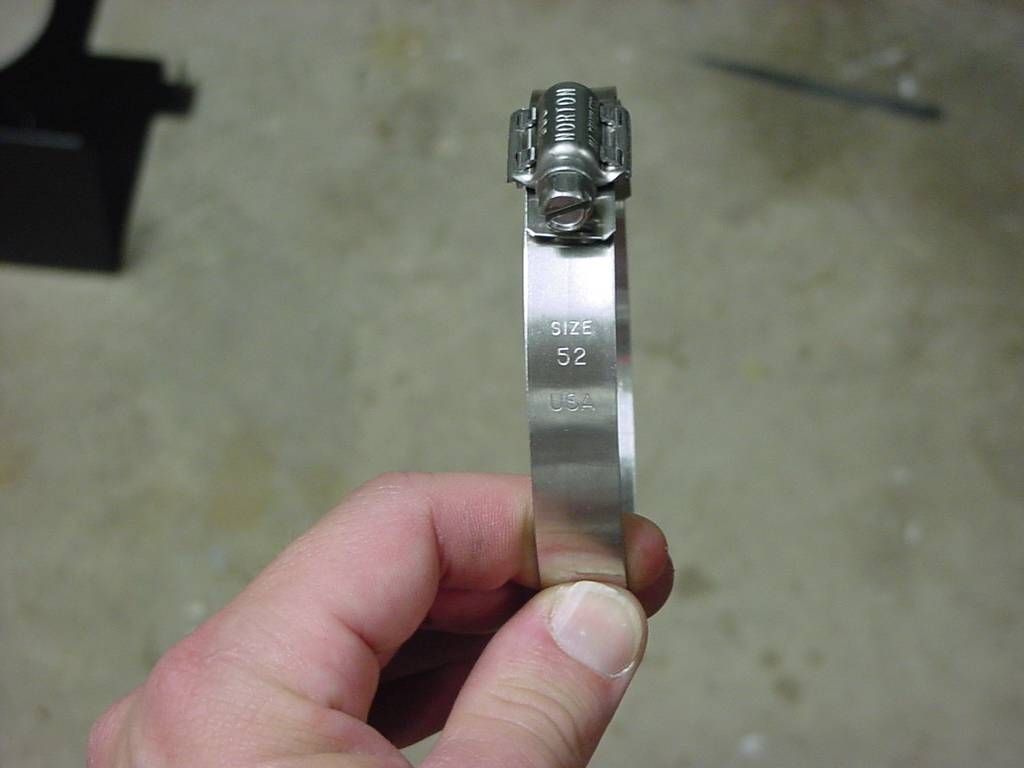
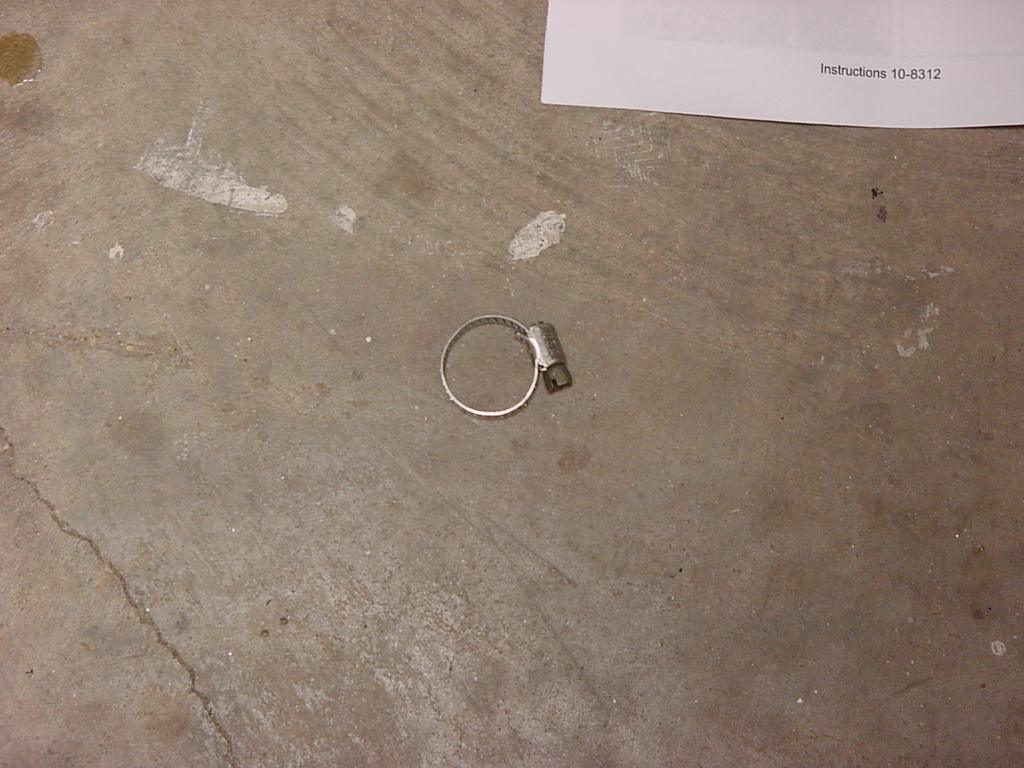
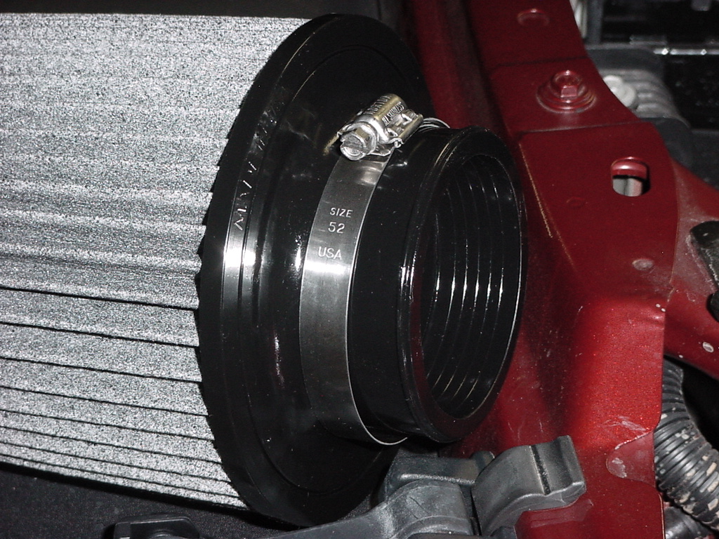
| Note: AEM provided three large hose clamps for this project. Size 44, 48, and 52. The numbers are stamped on the side of the hose clamp. |
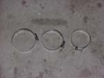 |
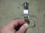
Size 44
|
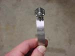
Size 48
|
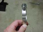
Size 52
|
| 22. Unscrew the Size 44 hose clamp and install loosely around the throttle body. |
|
 |
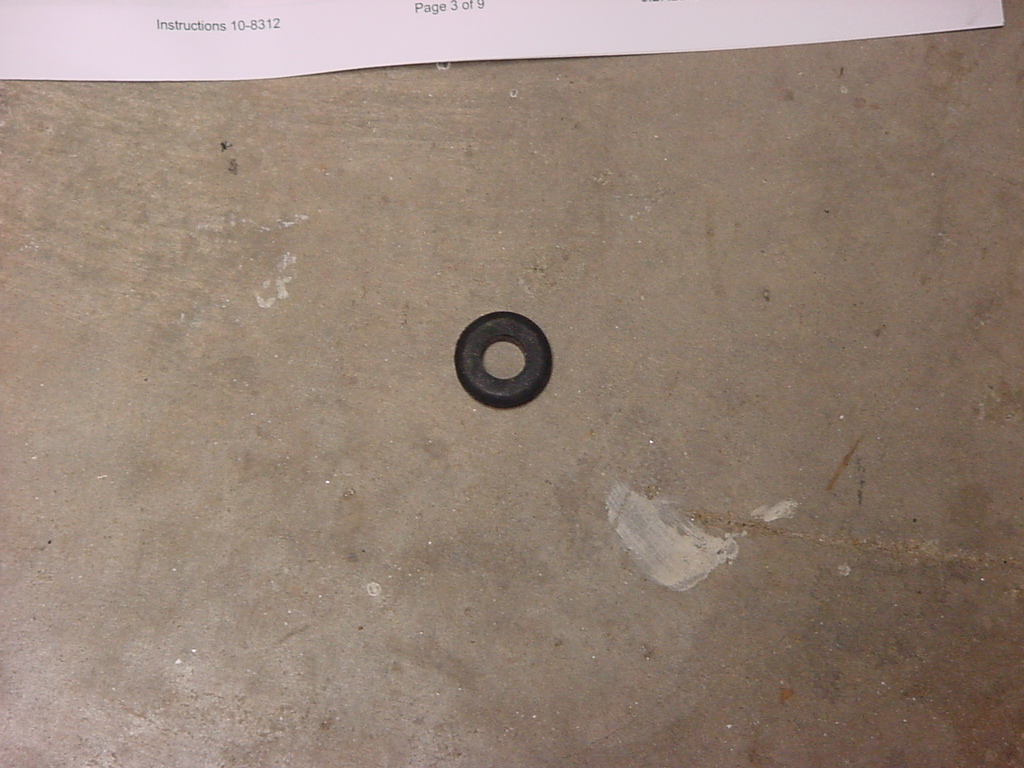
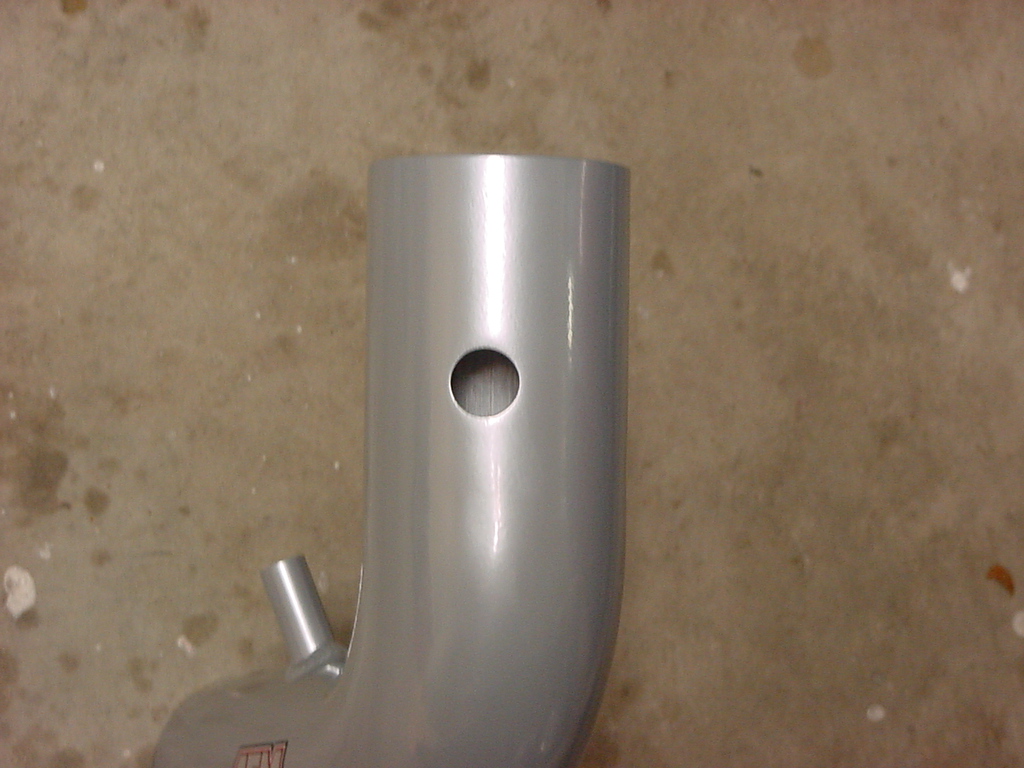
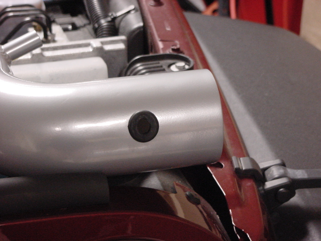
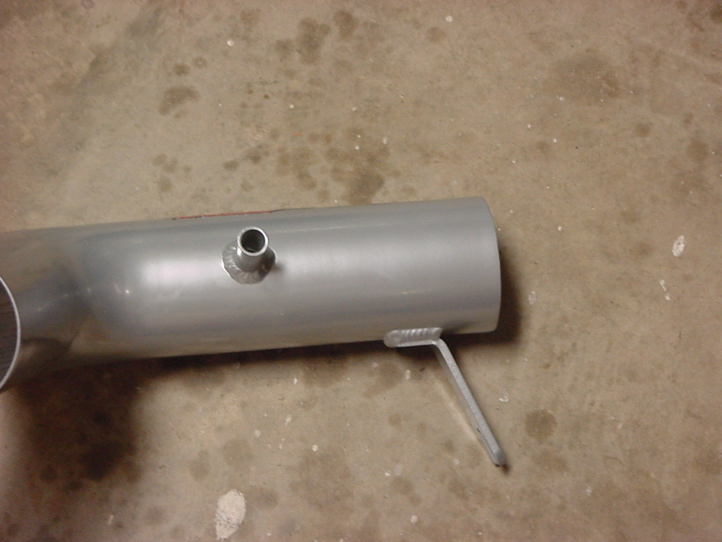
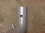
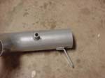
| 23. Find the small grommet and the intake pipe. You will insert the grommet into the hole on the side of the intake pipe. The AEM instructions have you do this after you have the pipe installed on the Jeep, but you still need to install the IAT sensor. |
 |
 |
 |
 |
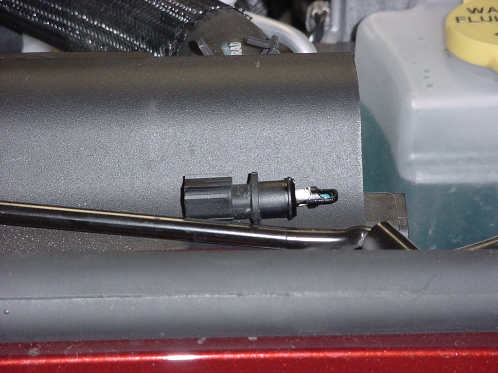
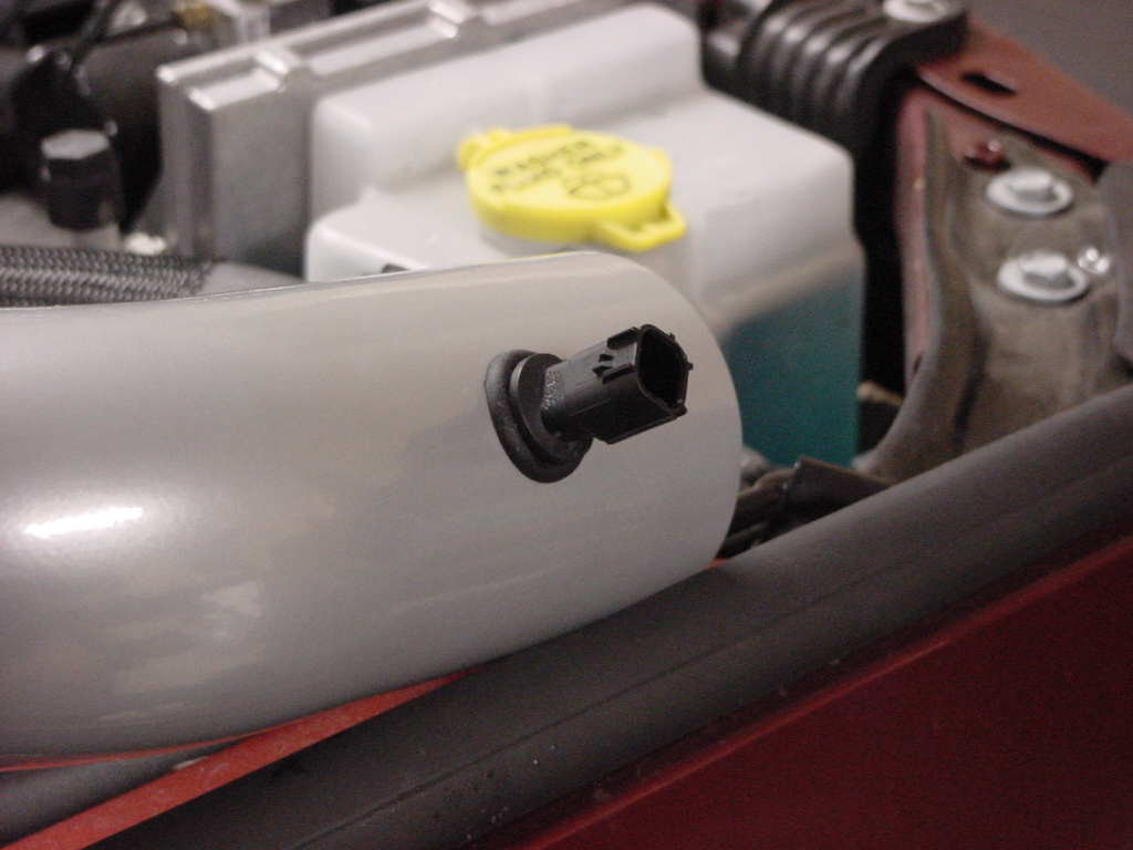
24. Install the IAT sensor in to the grommet. You will need to hold the grommet from inside the pipe to prevent the sensor from pushing it through. The sensor is a tight fit in the grommet. I ended up spitting on the grommet so that I could slide the sensor in.
NOTE: DO NOT APPLY ANY LUBRICANT OTHER THAN A LITTLE WATER, IT WILL DAMAGE THE SENSOR! |
|
 |
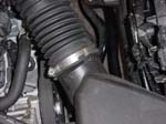
| 25. Insert the IAT sensor end of the inlet pipe into the rubber coupling on the throttle body. |
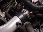 |
| 26. Unscrew the size 48 hose clamp and loosely install around the inlet pipe at the rubber coupling. |
|
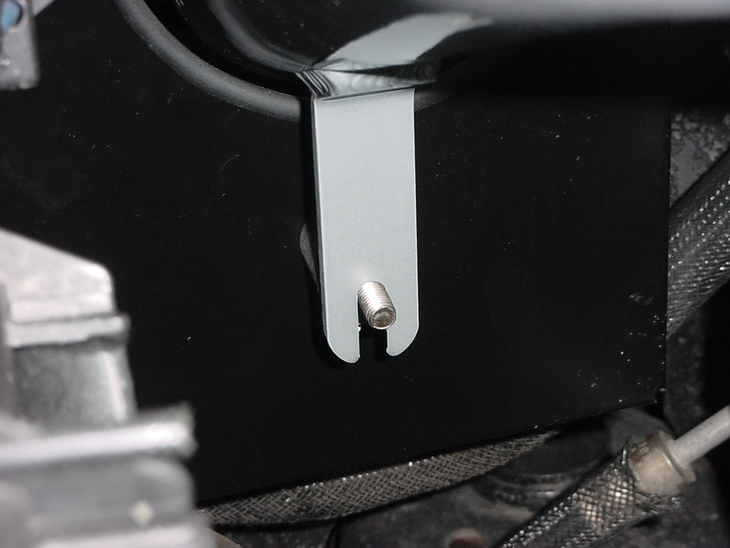
| 27. Install the tube into the hole on the heat shield and slide the bracket over the rubber mount on the heat shield. |
 |
 |
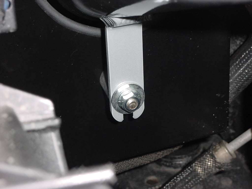
| 28. Loosely install the washer and nut on rubber mount. |
 |
| 29. Slide the small hose clamp over the end of the breather hose and reinstall the hose over the nipple on the intake pipe. |
 |
 |
 |
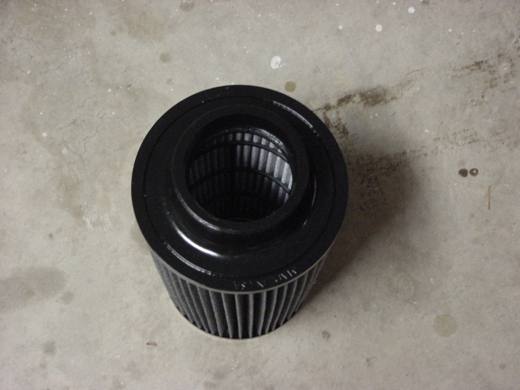
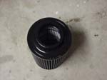
| Locate the dry air filter and the size 52 hose clamp. |
 |
 |
|
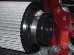
| 30. Place the Size 52 hose clamp over the end of the AEM filter and slide the filter over the end of the inlet pipe. This may require you to lift the pipe to slide the filter all the way on. Tighten the hose clamp with a 5/32" Socket. |
 |
 |
| 31. Reinstall the electrical lead to the IAT sensor. Push the red clip down to lock in place. |
 |
| Adjust the position of the pipe and filter. Make sure that the pipes and other components do not contact any other parts. Adjust as necessary. The IAT sensor sits a little high so I adjusted the inlet pipe up as much as possible on the rubber mount. |
| Tighten |
Check |
| Rubber bushing |
_____ |
| Breather hose, hose clamp |
_____ |
| Inlet pipe to coupling hose clamp |
_____ |
| Coupling to throttle body hose clamp |
_____ |
|
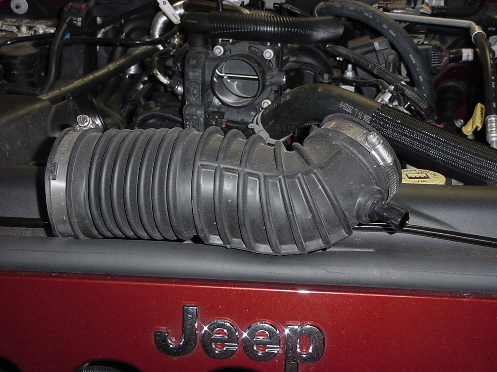
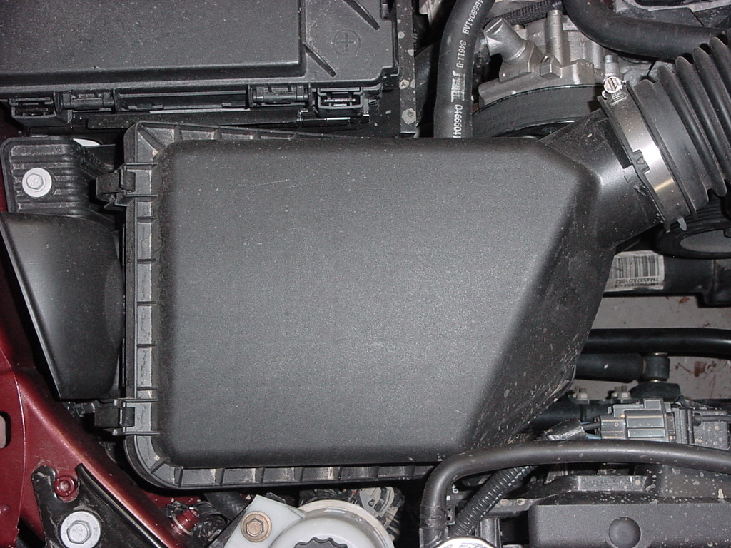
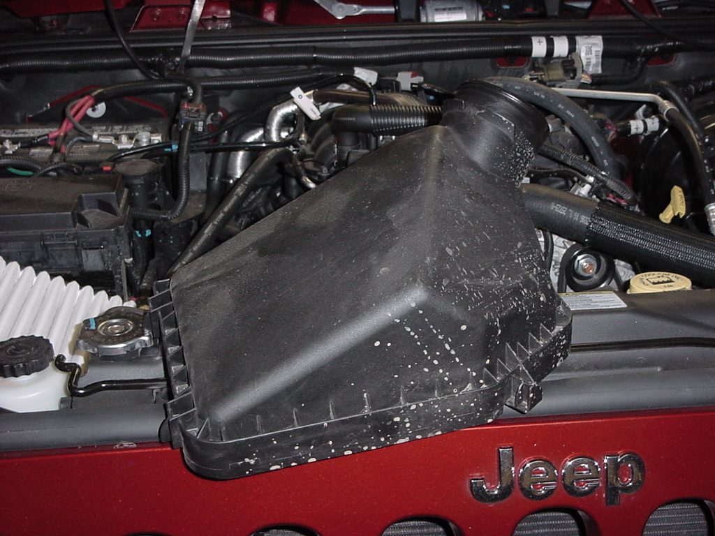
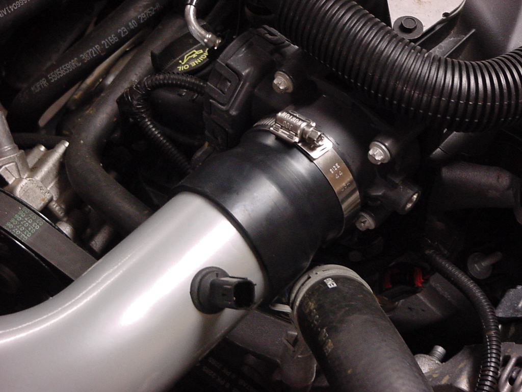
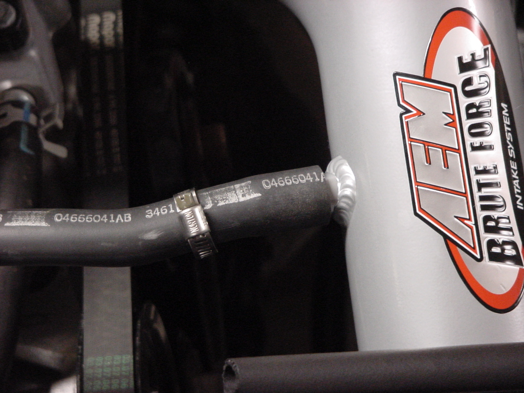
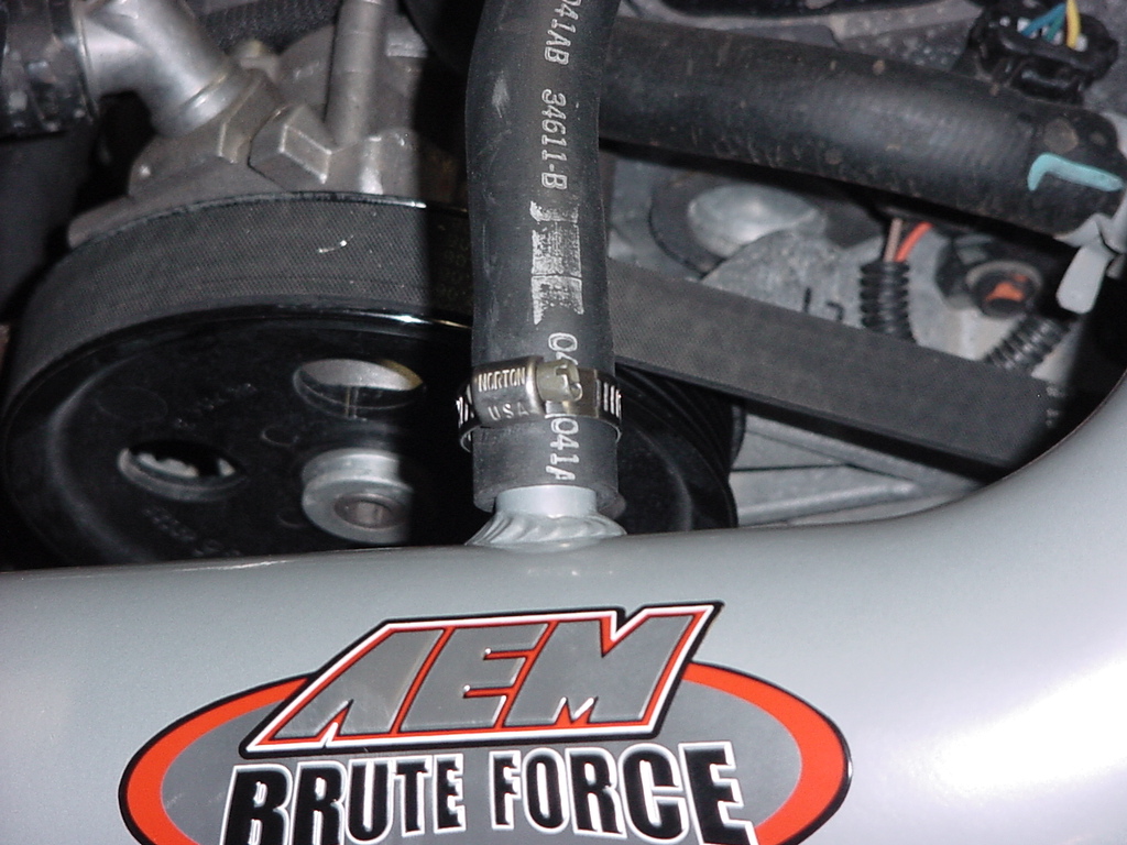
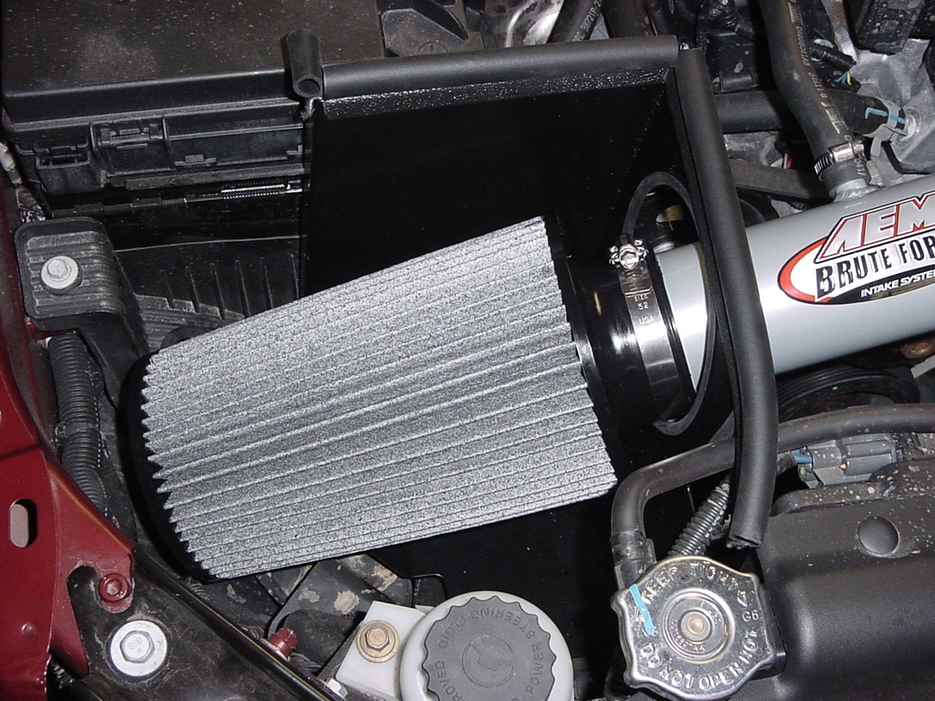
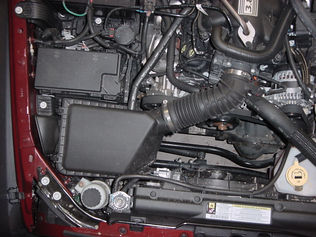
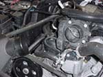
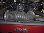
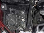
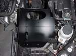
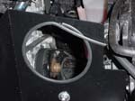
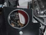
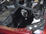
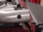
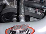
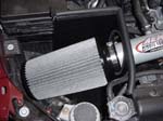
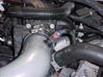
| Here is the before and after pictures. |
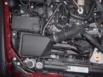
Before
|
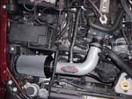
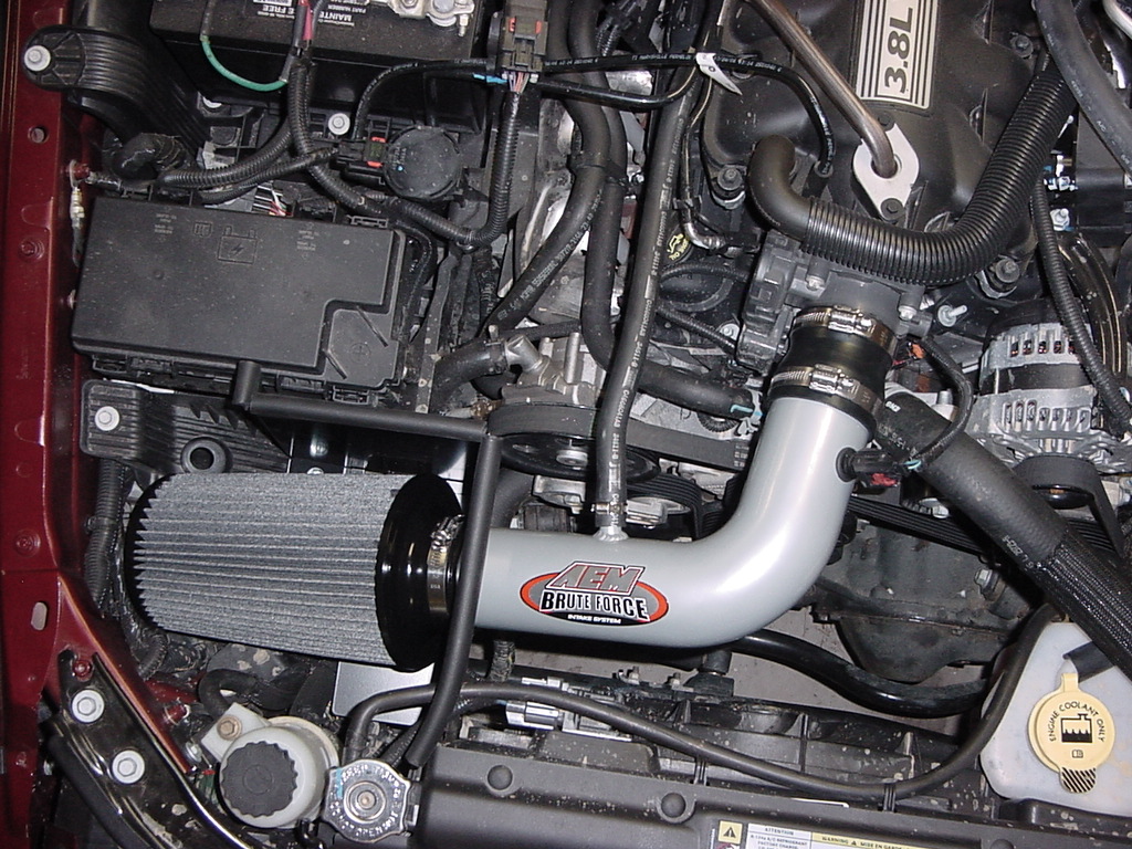
After
|