Communications while off road and even while you are on the road are important. Having a good radio system is important. The offroad community has been moving away from the old traditional CB radios and moving in the world of GMRS radios. For many years I ran a cobra 75wxt CB radio, but fewer and fewer members in the clubs and at events used these in the last couple years. GMRS while it does require you to get a license (currently $35 for 10 years to cover the family) it offers a much greater range and clairty over the CB radios. CB's were pretty much line of sight while off road and many times you couldn't reach someone that was just 1/2 mile ahead of you. The Midland MXT275 GMRS radio is a fairly budget friendly modification to mount inside of your vehicle and is completely capable with other GMRS radios. Since the MXT275 is hardwired to your vehicle you do not need to worry about the batteries being charged in your handheld GMRS radios. I do have a pair of GMRS handhelds that I take with me on the trail so I can use them for spotting, or loan one out to a member who doesn't have a radio with them. Yes I know that's not quite legal since they may not have a license, but from experience they usually end up with a vehicle mounted radio and license in the future.
| The Parts: |
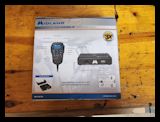
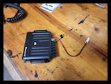
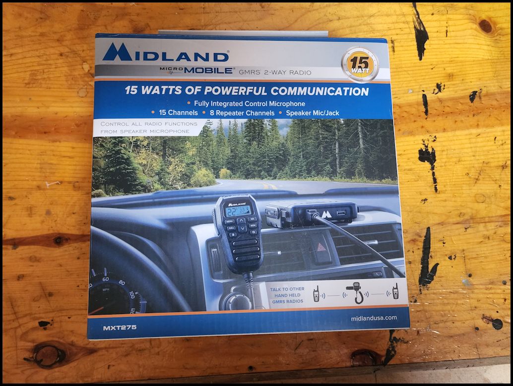
Midland MXT275:
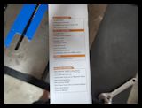
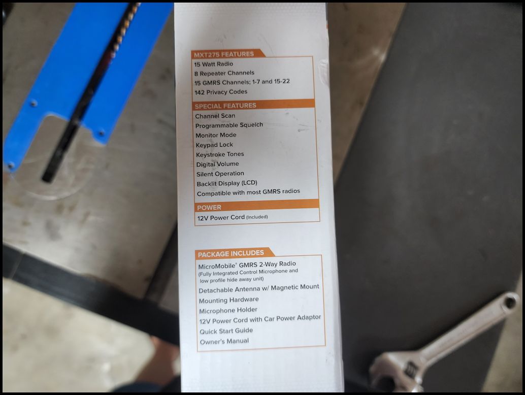
- 2-WAY RADIO - This 2-Way Radio features 15 high/low power channels (GMRS Channels: 1-7 and 15-22) with 8 GMRS repeater channels.
- 50-MILE RANGE - Full 15W Radio with an external magnetic mount antenna for extended range.
- 142 CTCSS/DCS PRIVACY CODES - The privacy codes give you up to 3,124 channel options to block other conversations.
- NOAA WEATHER SCAN + ALERT - NOAA Weather Scan will automatically scan through 10 available weather (WX) band channels and locks onto the strongest weather channel to alert you of severe weather updates. NOAA Weather Alert will sound an alarm indicating that there is a risk of severe weather in your area.
- Channel Scan to monitor radio activity
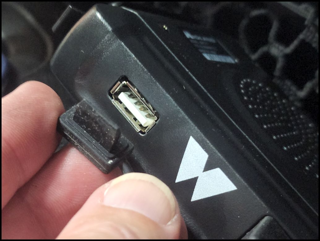
- USB-C charging port for charging mobile devices
- FCC license required
- dimensions with bracket: 5" D x 5-1/4" W x 1" H
- warranty: 1 year
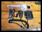
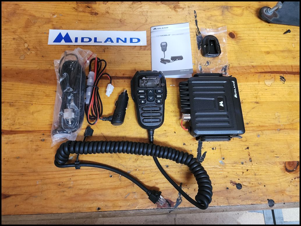
- INCLUDED IN THE BOX - Radio, Fully Integrated Control Microphone, Mount, Antenna with Magnetic Mount, Microphone, Microphone Holder, 12V Power Cord with Car Power Adapter, Owners Manual, and Quick Start Guide.
Range:
- No Obstruction - 50 miles
- Partial View - 15 miles
- Obstructed - <10
|
 |
 |
 |
 |
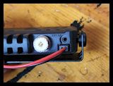
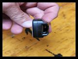
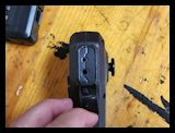
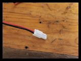
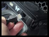
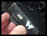
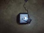
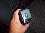
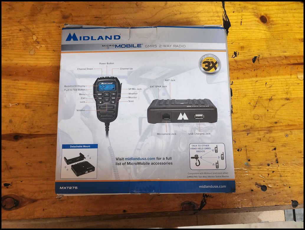
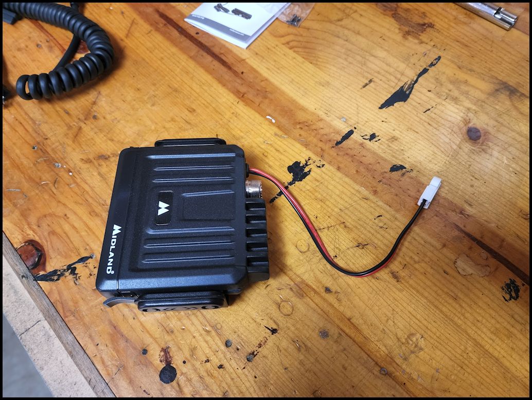
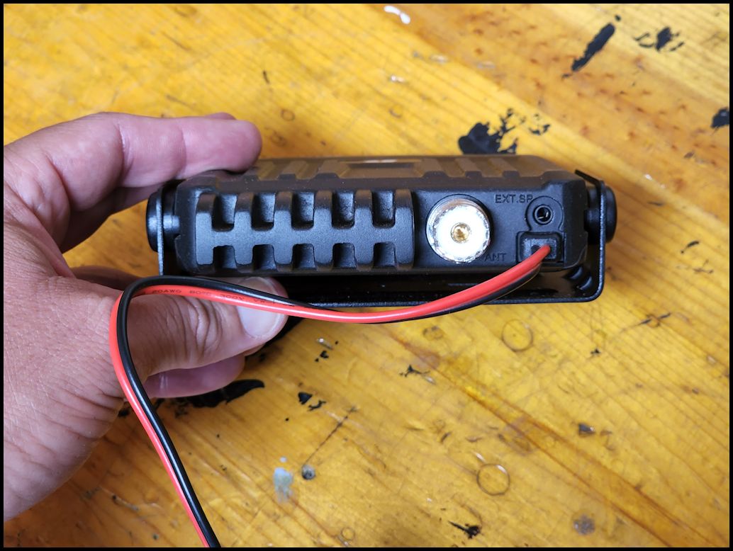
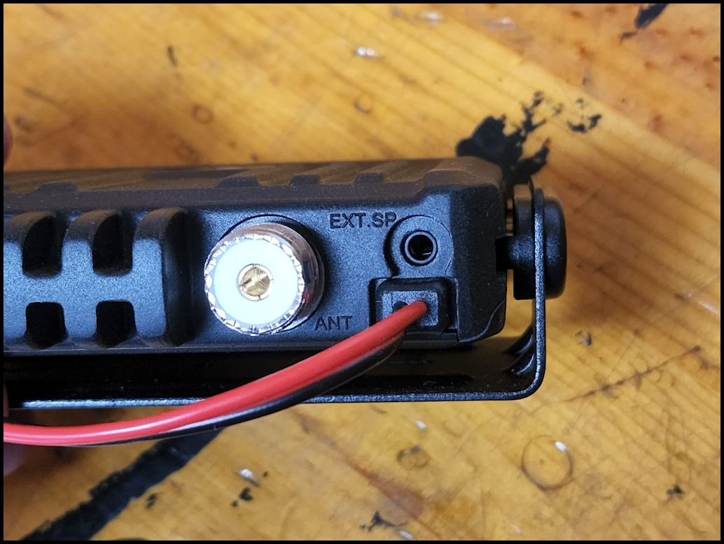
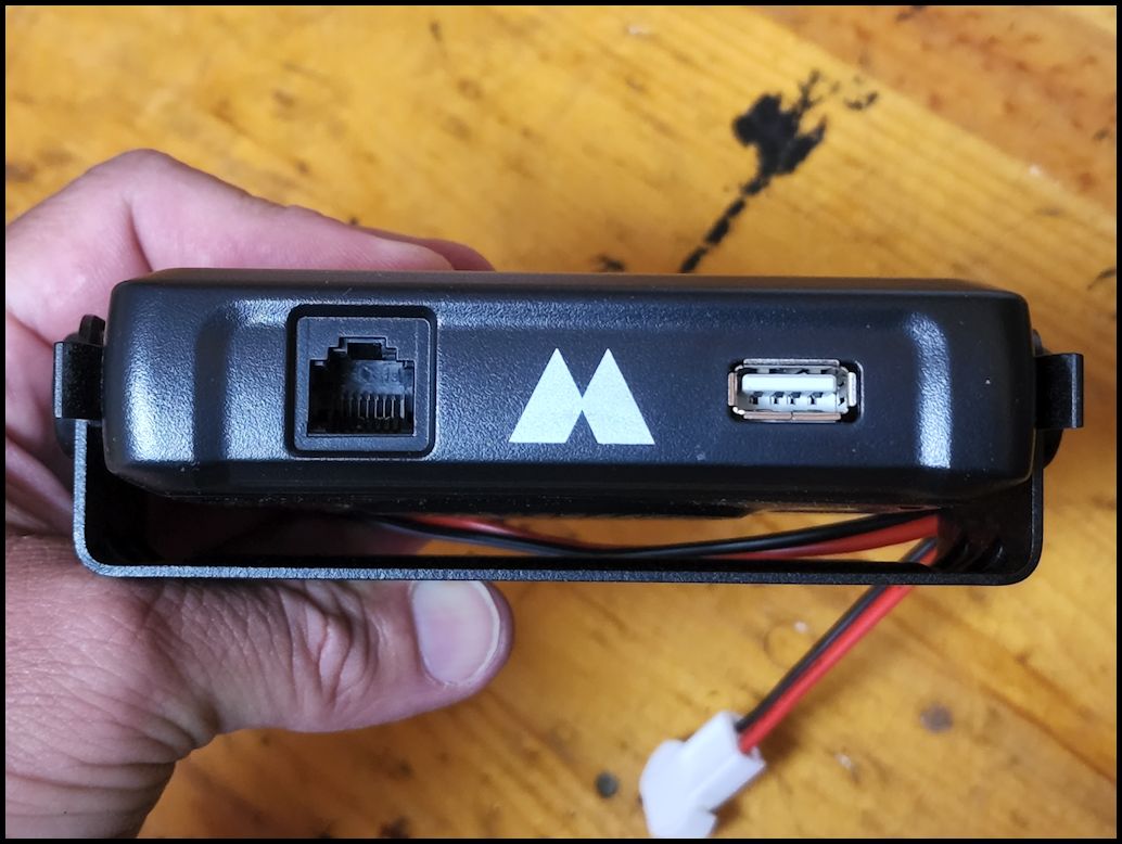
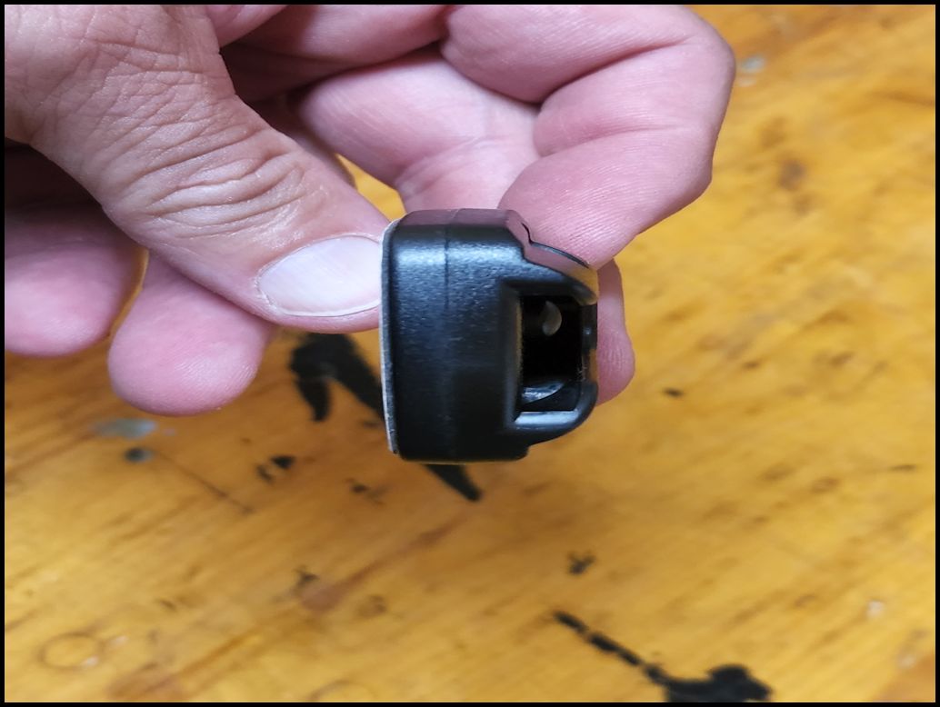
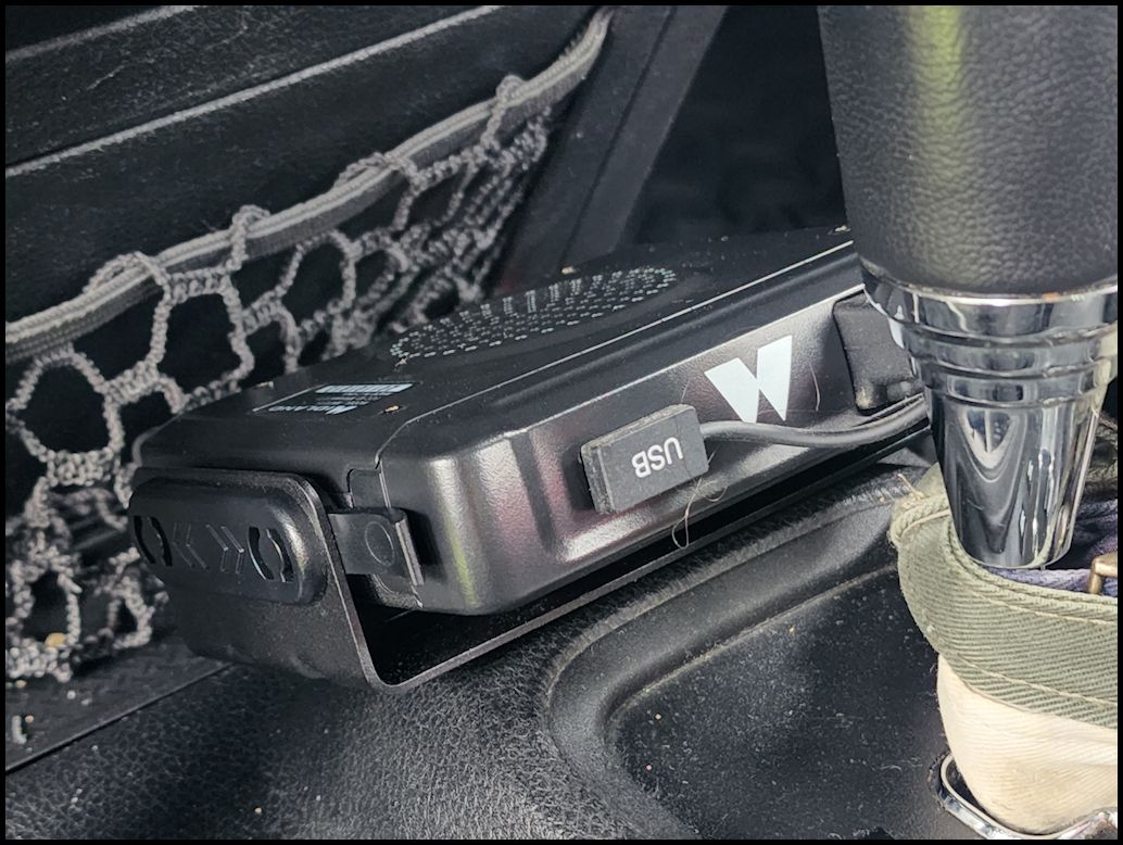
| The head unit is fairly small at about 5x5x1 inch. This allows it to be mounted in a lot more locations than a CB radio could. The back side has a SO-239 connector for the antenna cable along with a standard external speaker jack. A short power lead comes out the back that goes to a white connector for the power cable. The front has a RG45 jack for the handset along with a USB charging port. |
 |
 |
 |
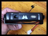 |
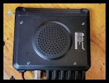
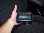
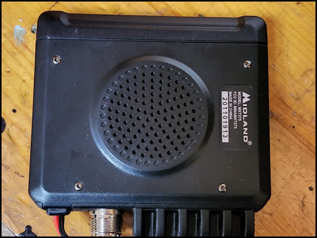
The bottom of the base unit does have an installed speaker and it is fairly loud if you turn the volume all the way up for the speaker. I did install this with the speaker pointed up, and going down the free way with the windows open I couldn't hear anything but noise, though as soon as I rolled up the windows it was really loud.
Note: You do need to go into the menu and switch the speaker mode to either the base unit or base unit and mic. |
 |
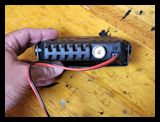
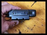
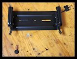
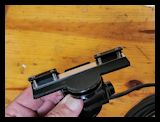
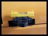
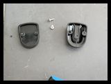
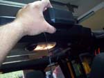
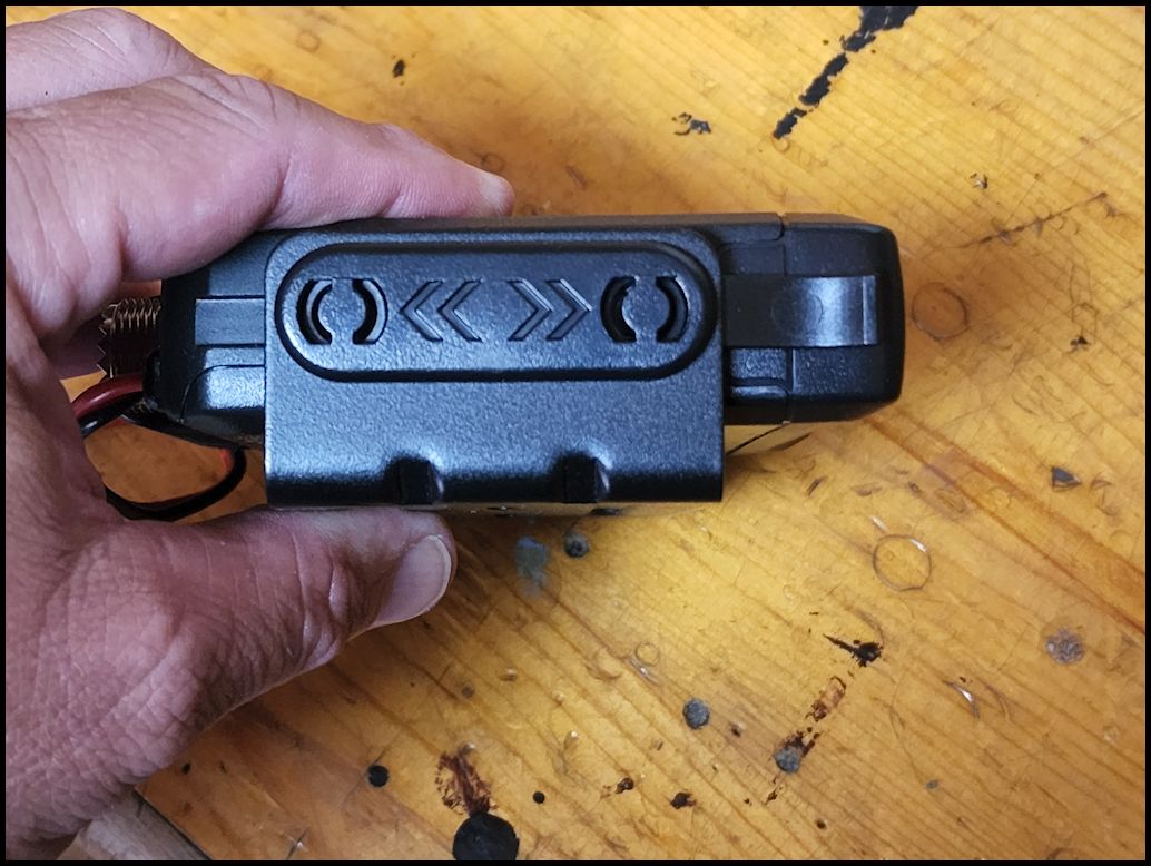
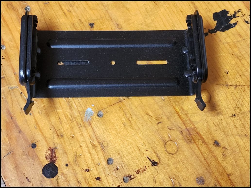
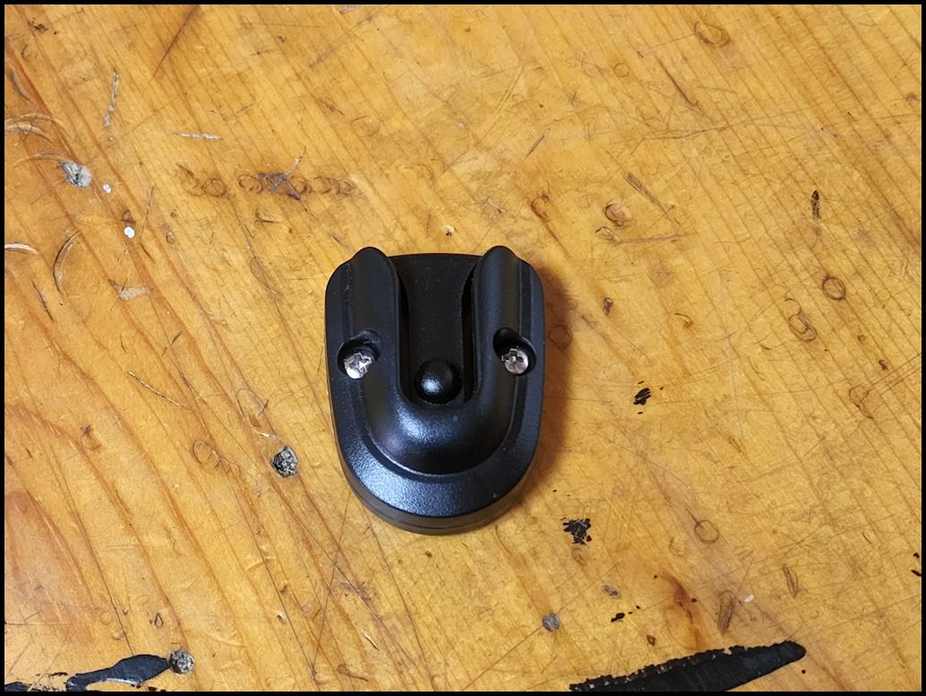
| Flip-Frame Detachable Mount. This allows slide-out removal of radio while bracket remains mounted. You can mount the bracket either down or up and still position the radio whichever way you want into the mount. I have mine currently mounted down with the radio flipped upside down and the speaker pointed up. To get the radio out you need to pull the two (2) tabs out while simultaneously pushing the radio forward in the mount. |
 |
 |
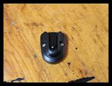
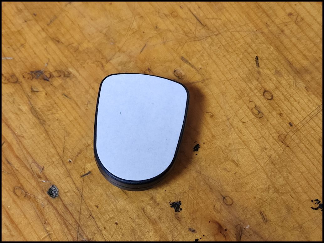
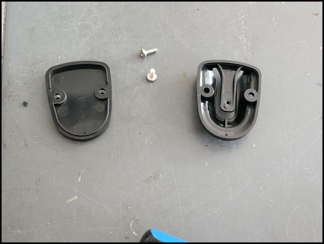
| The mic holder has a piece of double sided tape on the back to allow it to be mounted to most flat smooth surfaces. You can also screw mount it by removing the two (2) screws on either side, removing the back and then using those screws to screw into plastic or thin metal. I did try to use the CB mic mount that I had installed inside the Jeep, but I couldn't get the mic to go into that mount without a lot of force. |
 |
 |
 |
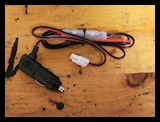
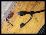
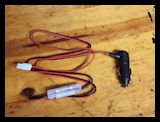
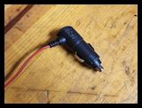
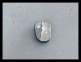
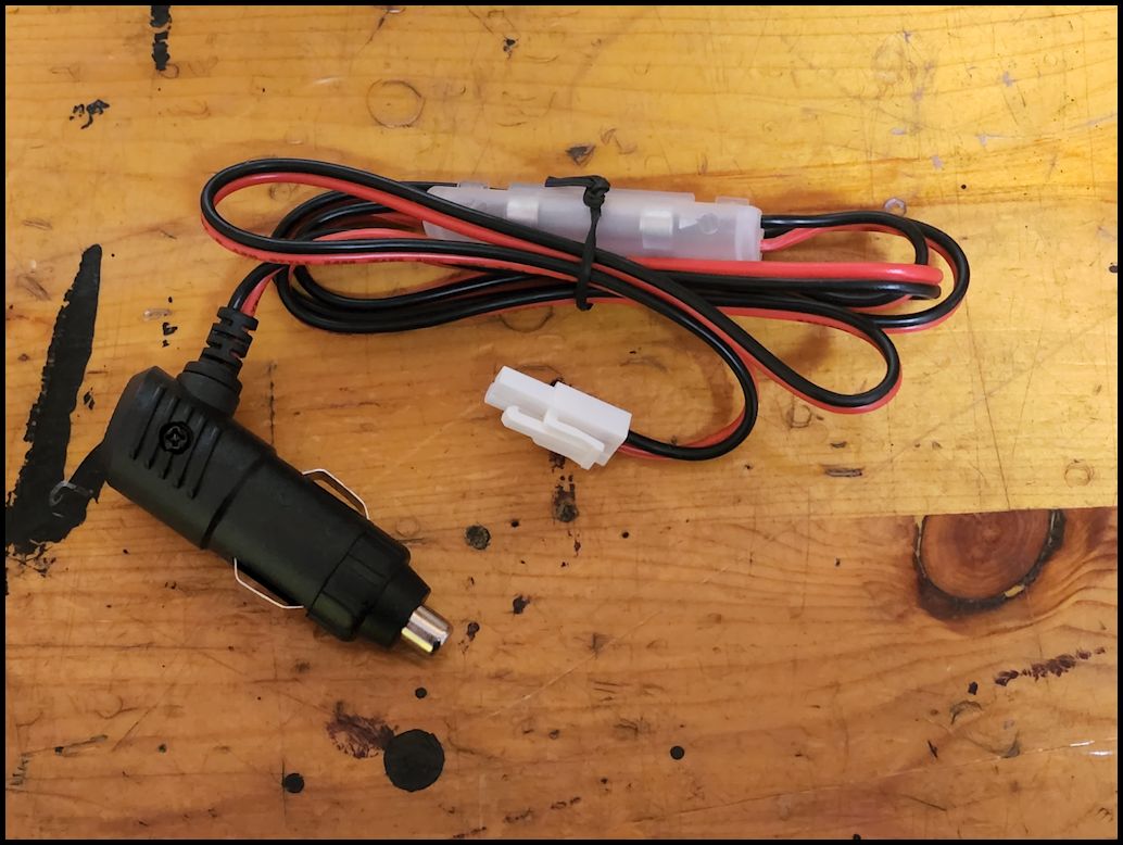
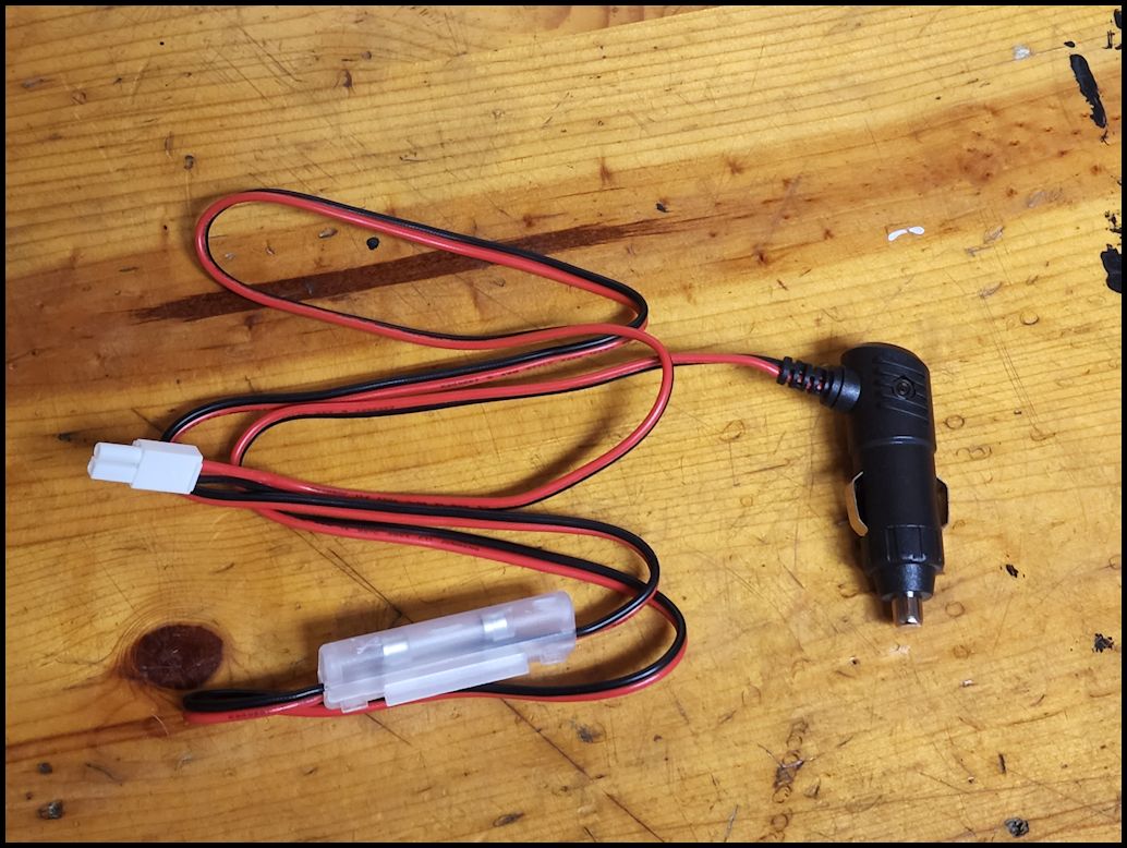
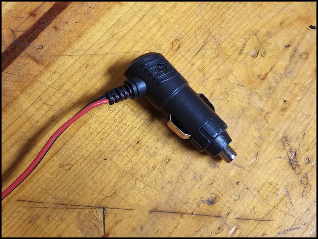
| The radio comes with a standard 12 Volt accessory plug. Simply plug the radio into your vehicles 12-Volt accessory port for power. You will need to cut the plug off if you intend to hardwire it into your vehicles system. The plug is fused with a glass fuse (there is an second fuse inside the plastic housing). I am not a fan of type of fuse, but it is definetly nice that a second fuse is included. There is another fuse located inside of the accessory plug. You will need to unscrew the end of the plug to access the fuse. |
 |
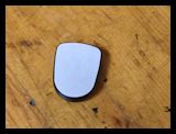
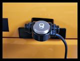
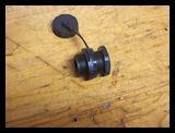
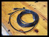
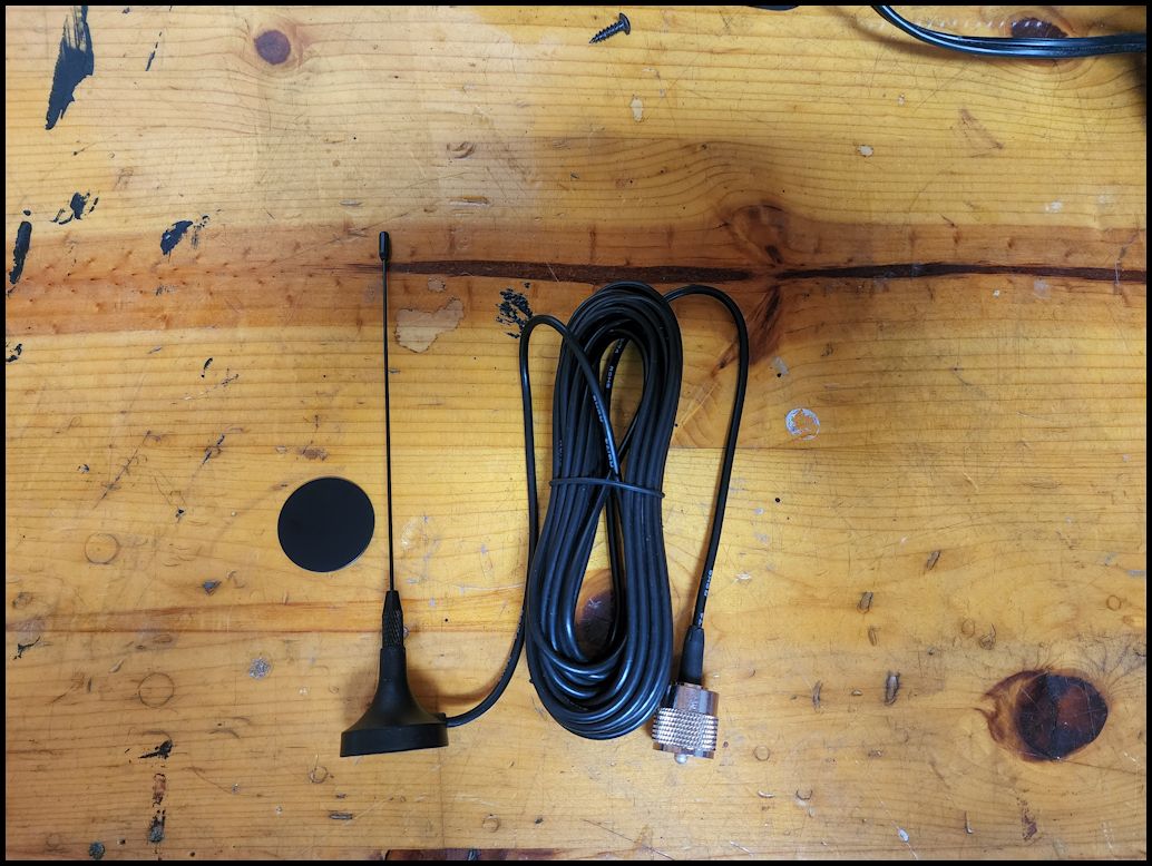
| The supplied antenna has a magnetic base along with a adhesive metal disk so that the antenna can be mounted on a non magnetic flat surface. The cable is about 20 feet long (6 meters) and has a PL-259 connector on the end. This is plenty length to reach from the MXT275 to almost anywhere on a vehicle. The antenna is only about 8" high. |
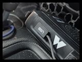
 |
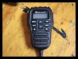
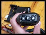
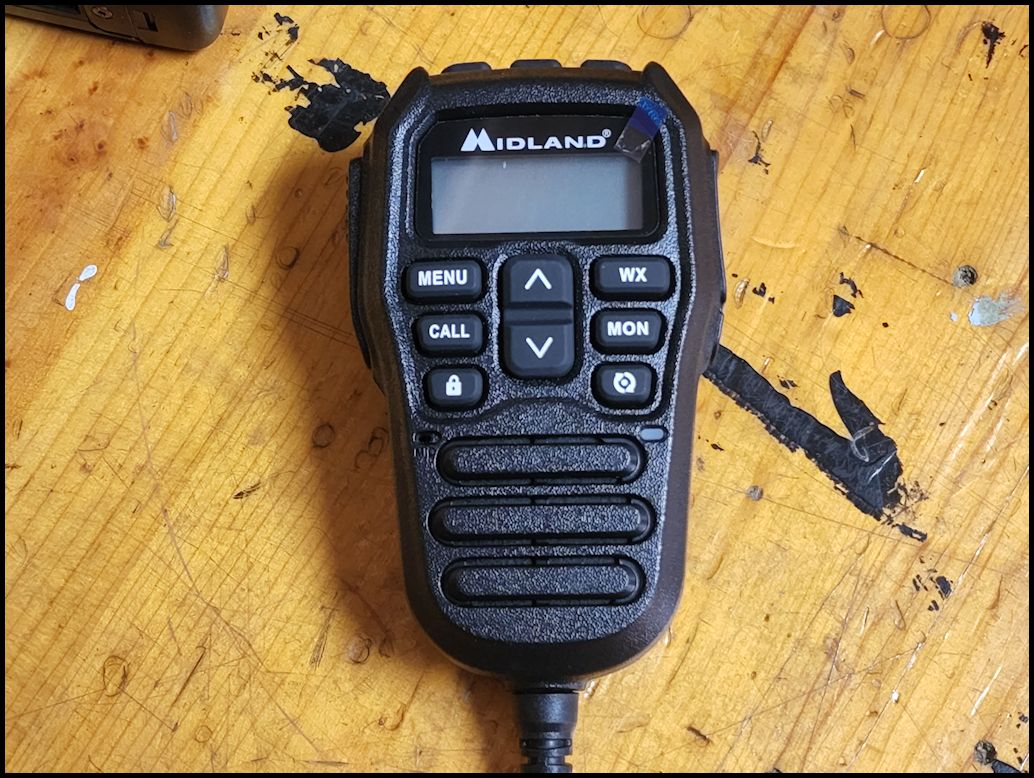
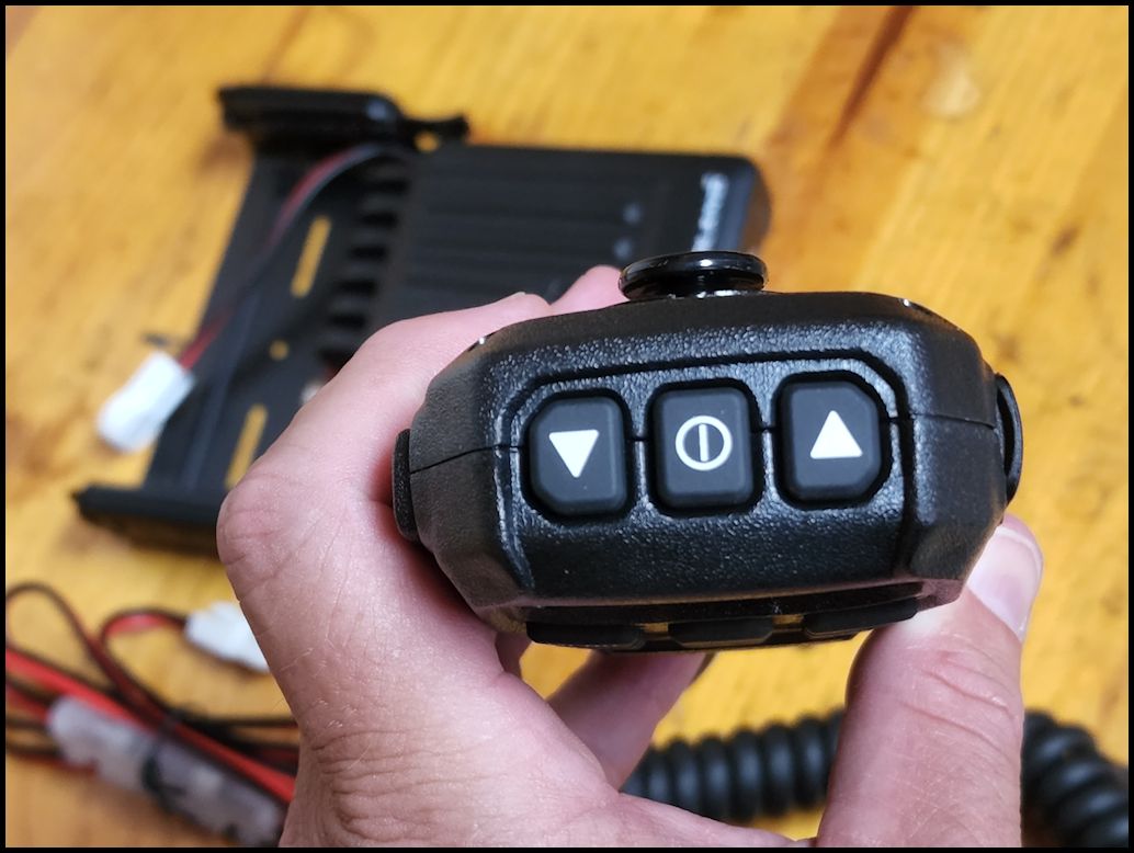
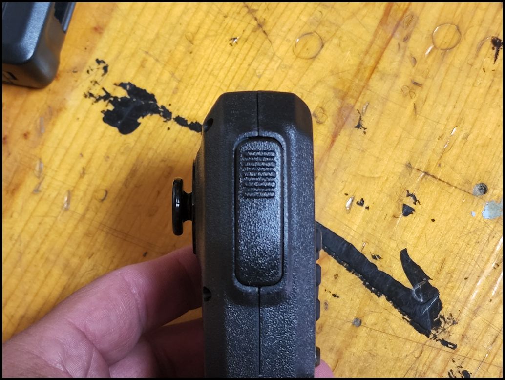
| The MXT275 incorporates all radio controls directly into the microphone for easy operation, once you figure out how to operate all the buttons. I still press the wrong buttons for volume and channel. |
 |
 |
 |
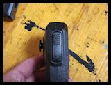 |
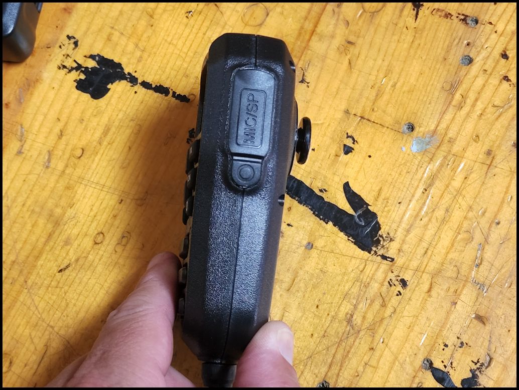
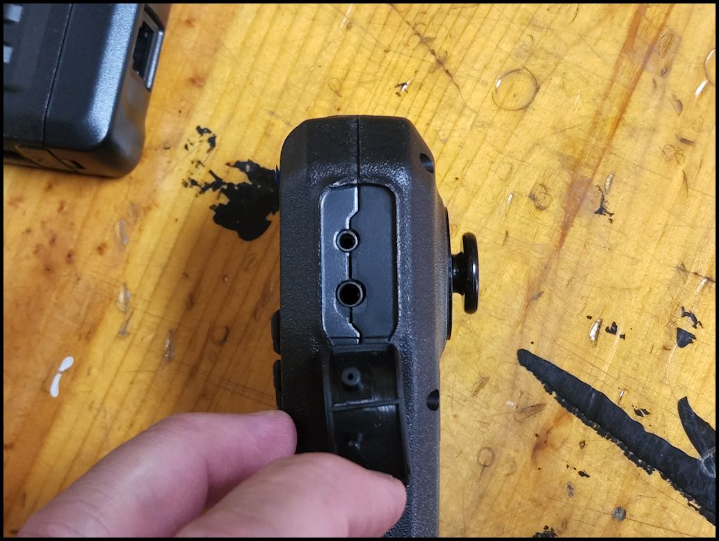
| The mic does have a speaker Jack behind a rubber cover on the right side. This is an accessory input for the use of Midland FRS and GMRS radio headsets. I need to see if the radio ear pieces that I have with the Baofeng radios work on this, they are the same style connector. |
 |
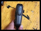
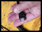
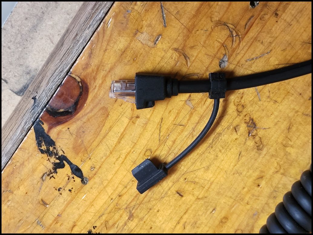
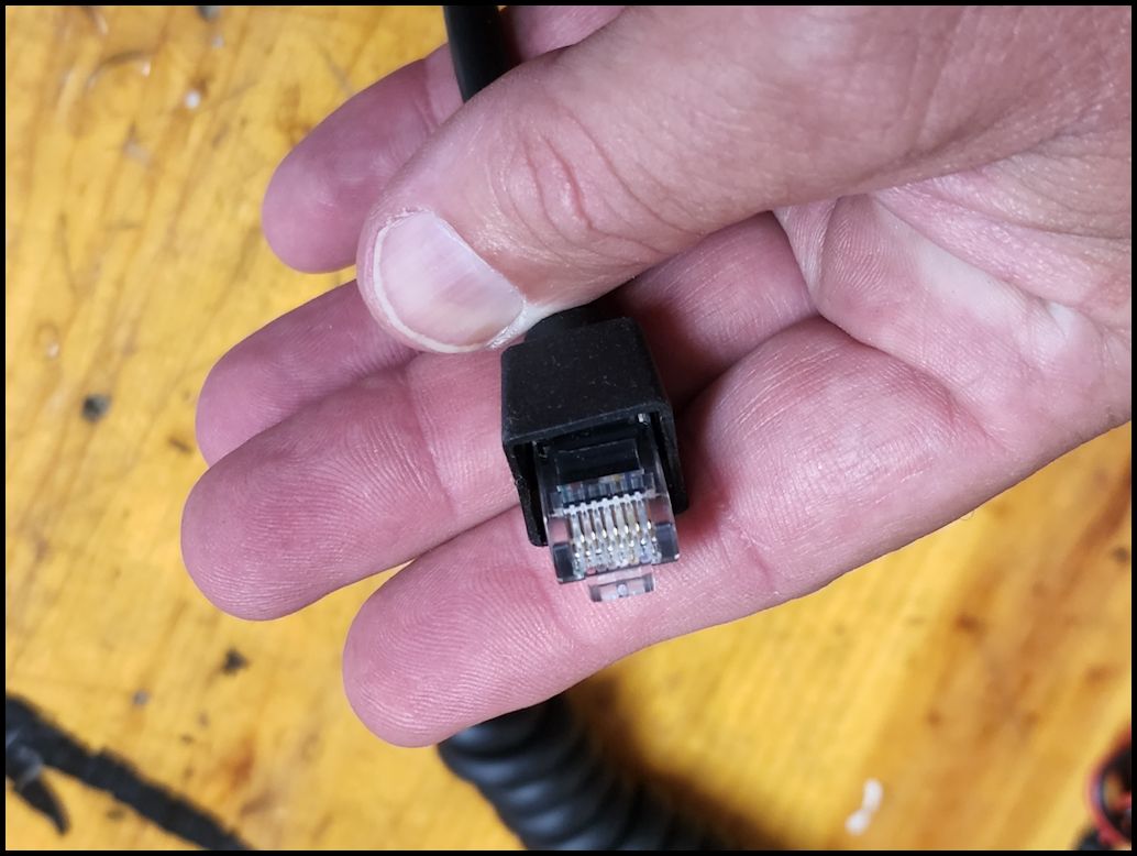
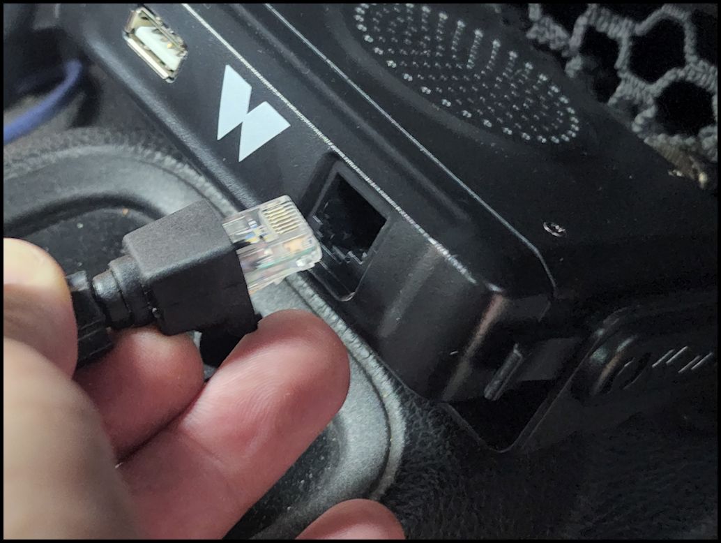
| The microphone cord is terminated in a standard RJ45 ethernet connector and includes a tethered cover for the USB port on the box. I only wish that the box had covers for the USB port and ethernet port attached. I think this would be a much better way to protect the ports when the mic is not connected. |
 |
 |
| |
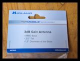
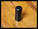
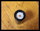
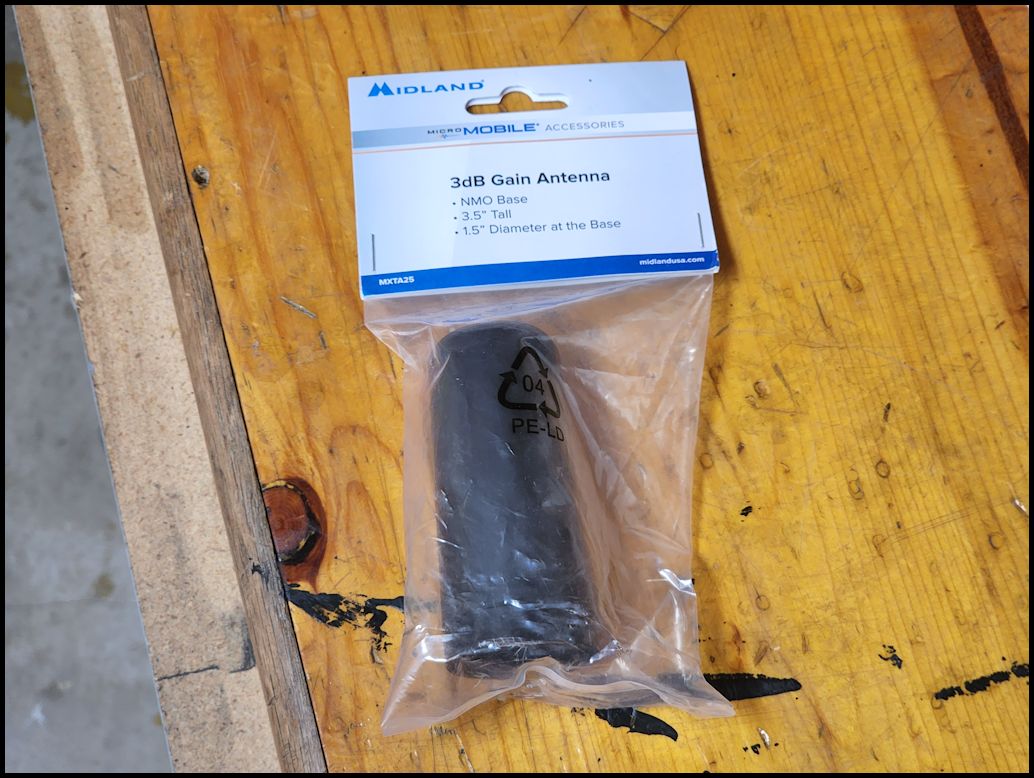
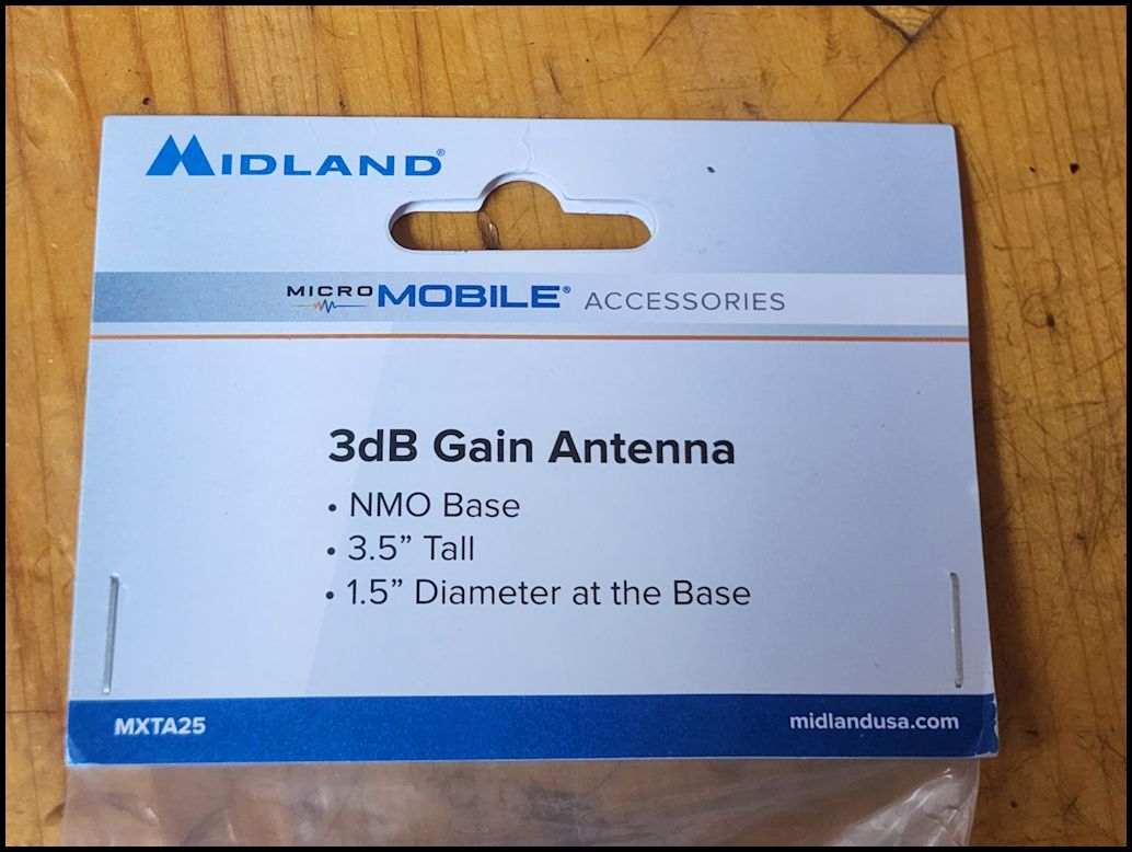
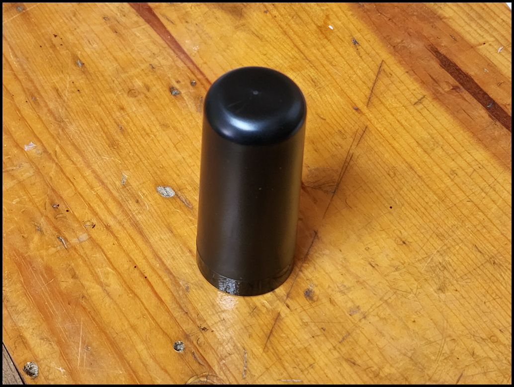
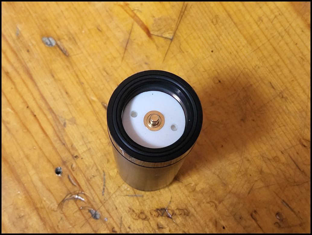
Midland MXTA25 3dB Gain Ghost Antenna with NMO Connection:
I have run some basic tests comparing this to the regular magnetic mount antenna that comes in the package. I was actually really surprised at the signal quality provided by the basic antenna in the kit. The only time I noticed much of a difference was in areas where my line of sight was really limited the MXTA25 was able to pick up a signal better than the small antenna. I will have to see how this antenna handles the branches on the trail. The good thing is that it stays out of my line of sight inside the Jeep.
- 3.5” overall height
- 1.5” base diameter
- Mobile Antenna Mounting Type – NMO
- Frequency – 462 MHz
|
 |
 |
 |
 |
| |
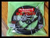
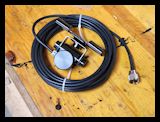
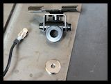
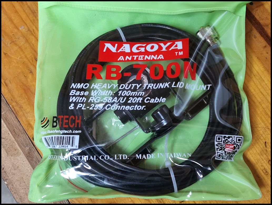
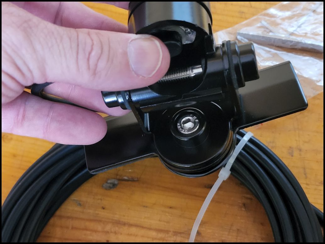
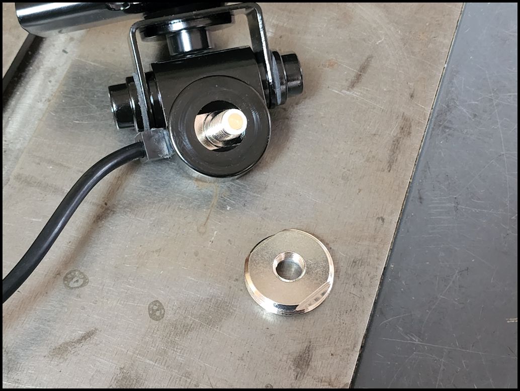
Nagoya RB-700N Heavy Duty Universal (Multi Axis Adjustable)NMO Lip Mount:
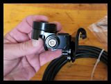
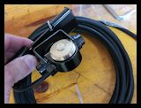
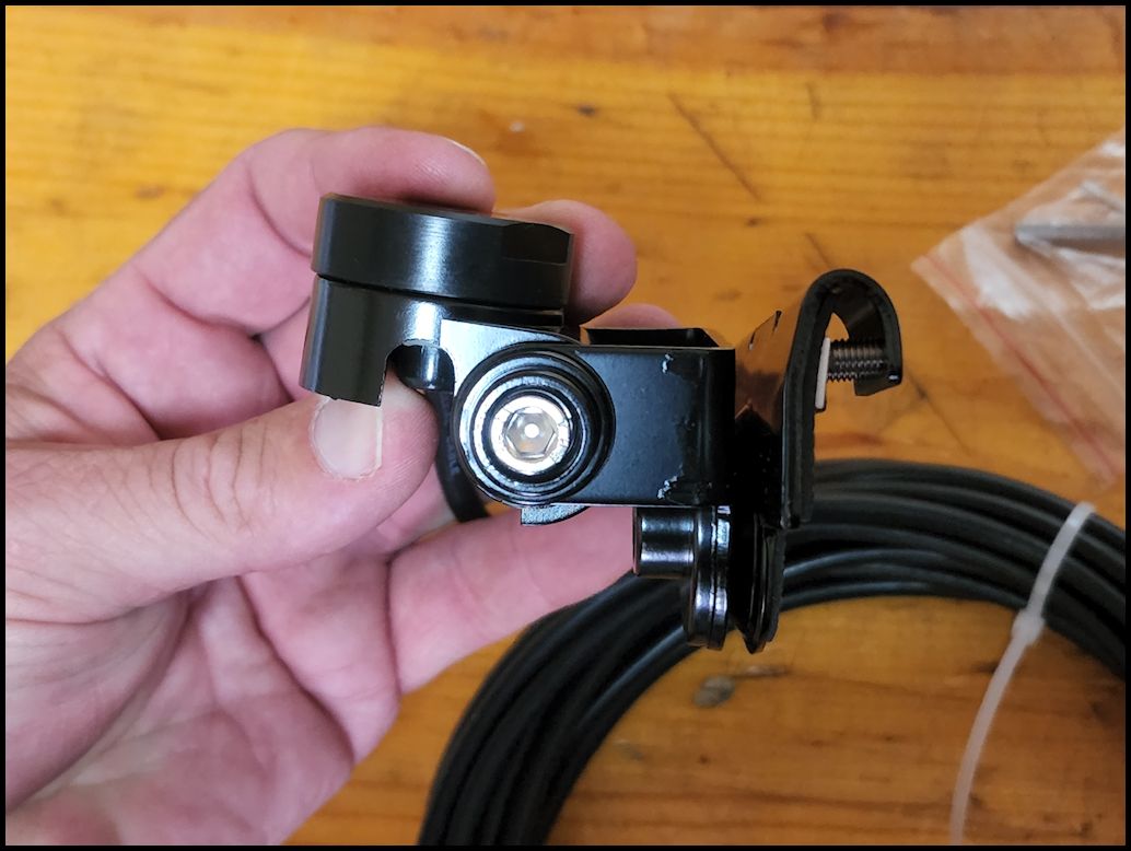
The Nagoya RB-700N is a Lip Mount solution that provides a NMO mount for a vehicle mounted antenna. No holes or drilling required and no magnetic antenna to slide around on your paint. The antenna mount has two (2) individual axis adjustable rotation points (360 degree rotation base). This can be used on almost any angled trunk, hatchback, or lip mount locations. The mount comes with rubber pads on the lip to protect your vehicle from rubbing directly on the mount. The mount is compatible with any NMO antenna. Pairs with most NMO connection HF, VHF and UHF antennas and will supports antennas up to 72 inches tall (antenna's this tall will still place some leverage action onto the mount which may cause bending issues).
Coax: Solid Brass Chromed NMO mounting, Gold contact pin, PTFE insulator, 20ft. RG-58A/U cable, Tinned copper braid 95%.
Includes:
– RB-700N NMO Lip Mount
– 20 feet of 50 ohm low-loss RG-58A/U Coax with a PL-259 Connector
– Rain Cap
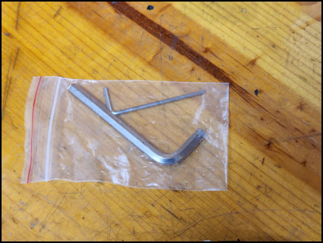
– 2 Allen wrenches |
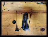
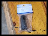
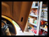
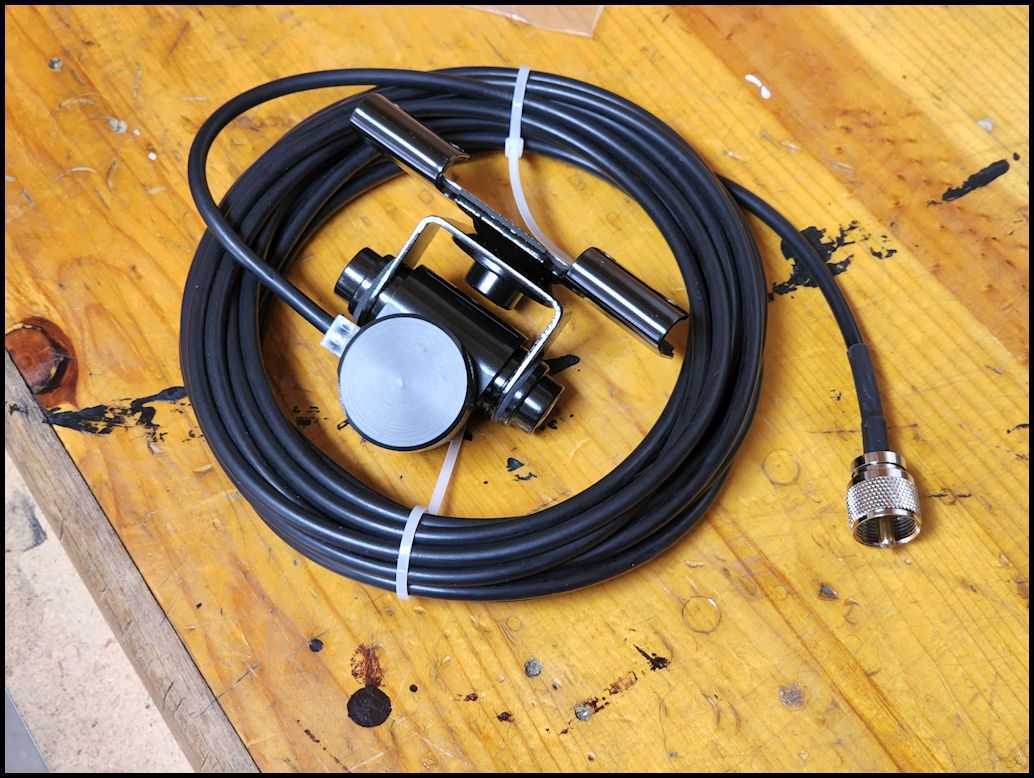
| The antenna mount comes packaged in a nice plastic bag that could be hung on a hook in the store. I left mine sitting in the garage for a while before I pulled it out and the clear vinyl shell stuck to the antenna cable. The bag was pretty sturdy, so I packed up a bunch of loose parts into it threw it into my parts drawer. The cable was zip tied in a coil with the antenna mount in the center. |
 |
 |
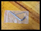
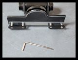
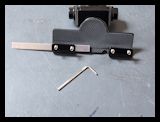
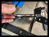
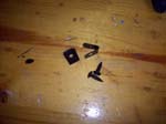
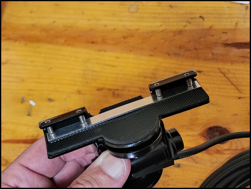
| Nagoya included a package with two (2) different sized allen wrenches. The larger one fits the allen bolts that control the pivot points on the mount for the antenna, while the smaller one is for the fourn (4) allen screws on the backside of the mount that hold the mount to the lip of the hood, or trunk. |
 |
 |
 |
 |
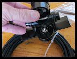
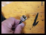
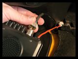
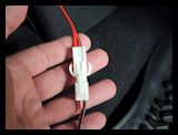
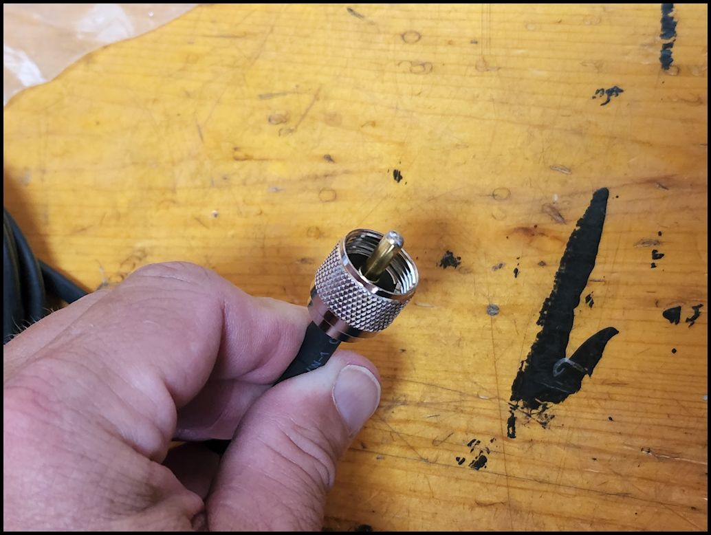
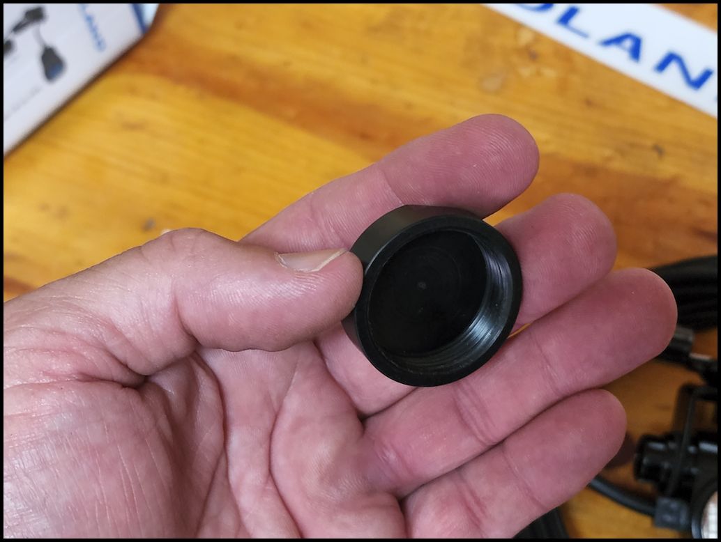
| Comes with a standard PL-259 connector on the end of the cable. This screws into the back of the MXT275. It is a tight fit, so you really need to get it lined up perfectly straight to get the pin into the connector on the radio before you can screw it down tight. The end on the Nagoya does not come off like the one on the Midland cable. This can become an issue when you are feeding it into the cab of the Jeep from the engine compartment. |
 |
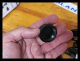
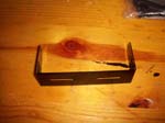
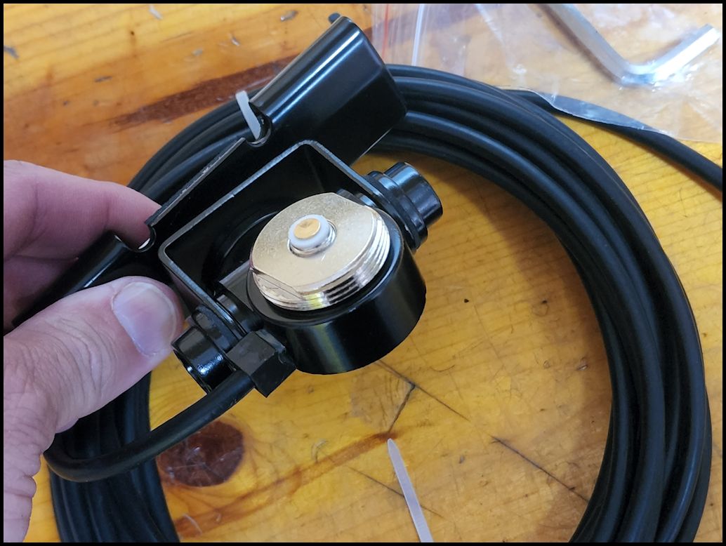
| The NMO mount comes with a rain cover that can be used when the antenna isn't mounted. This is a good idea since the antenna is just screwed on hand tight and can easily walk off on it's own. |
 |
 |
| |
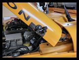
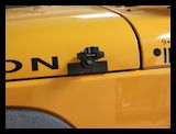
| Antenna Mount Installation: |
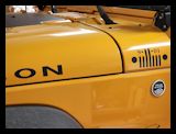
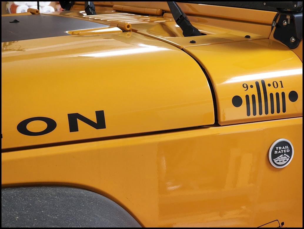
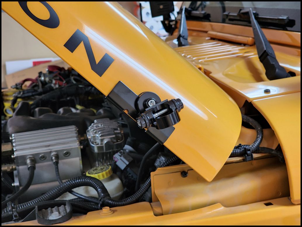
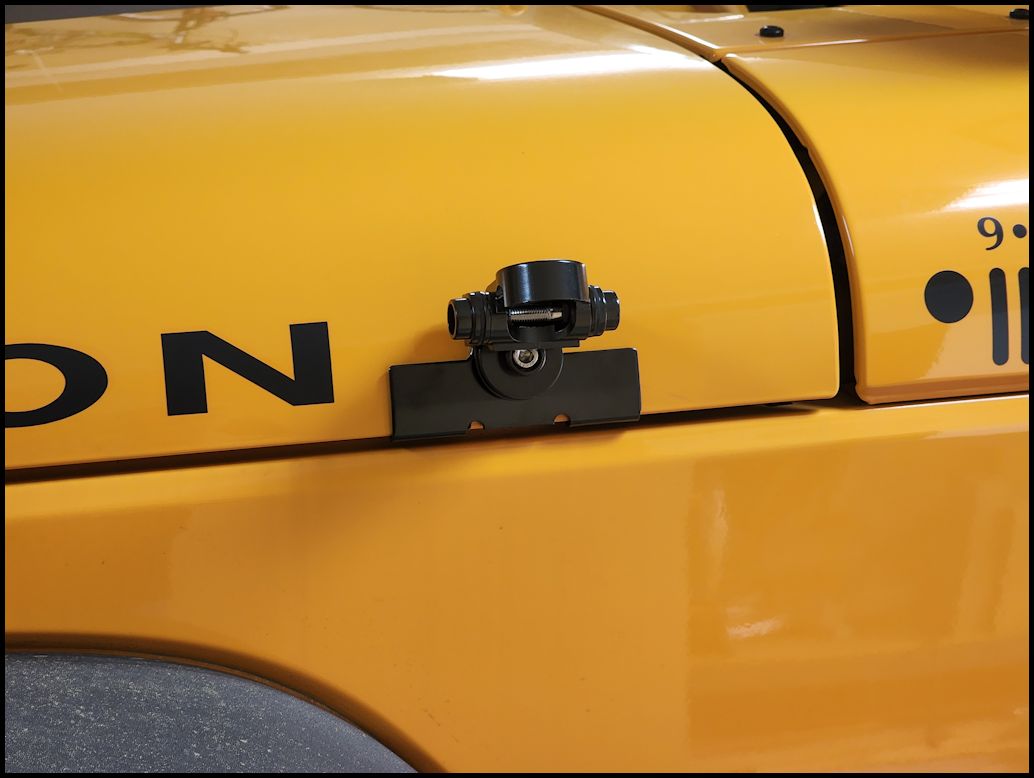
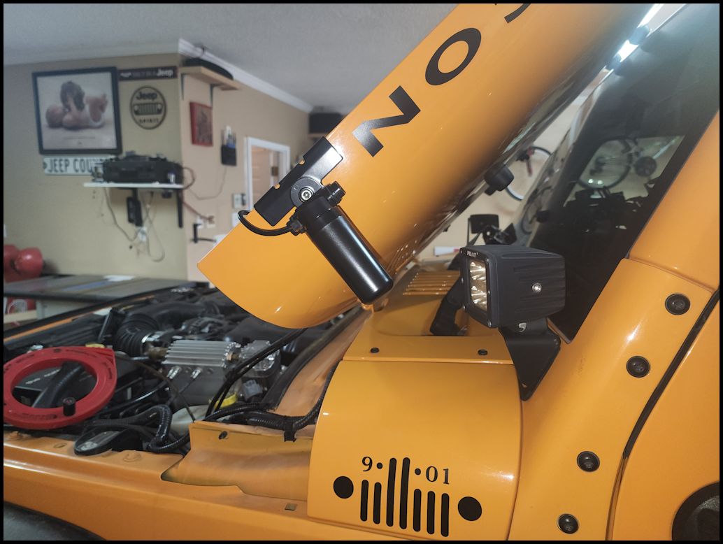
| I choose to mount the antenna on the edge of the hood on the driver side, just behind the Rubicon lettering. The antenna mount comes with 20 feet of cable so there is plenty of length to mount the antenna just about anywhere on the Jeep and run the wire to just about anywhere inside the cab of the vehicle. You will most likely still have some cable length left over. |
 |
 |
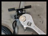
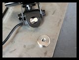
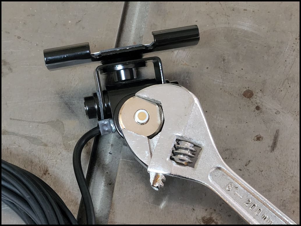
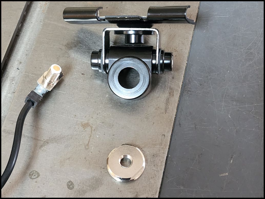
| Remove the NMO mount and cable from the mounting bracket. Use an adjustable wrench to unscrew the large mount ring from the inner pin. I only had to turn it about 1/2 turn before it was loose enough to unscrew by hand. Remove the antenna cable from the bottom of the mount. I recommend screwing the ring back on to the pin so you don't loose it. |
 |
 |
 |
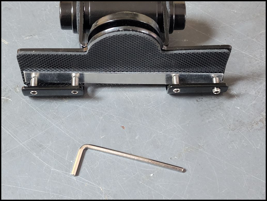
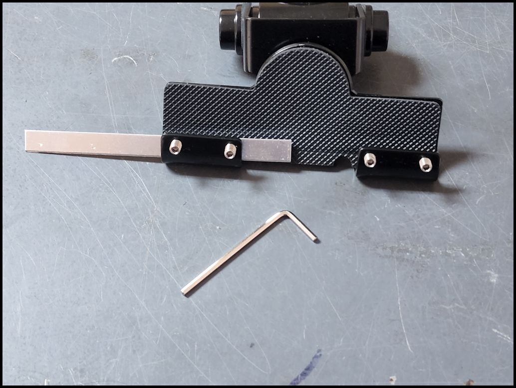
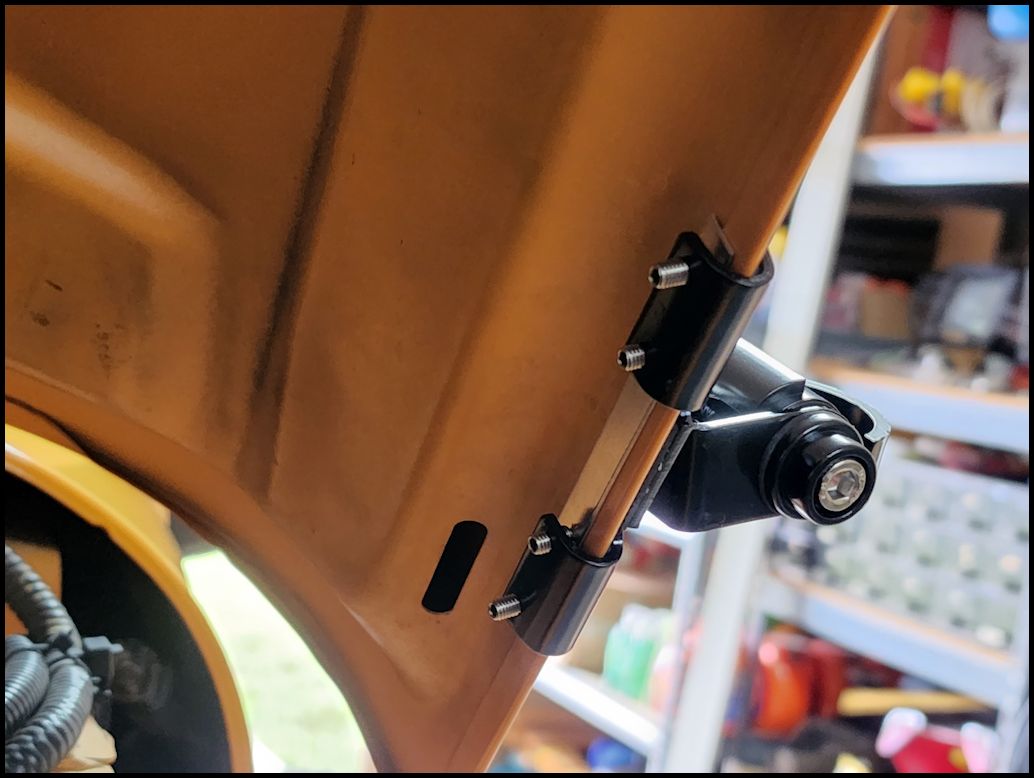
| Unscrew the four (4) small allen screws from the back of the mount. This will free the metal bar that they are holding. I backed the screws out until they were flush with the inner edge of the lip. Becareful you don't screw these out all the way and drop one, they are difficult to find once they hit the floor. |
 |
 |
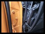
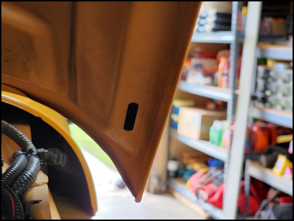
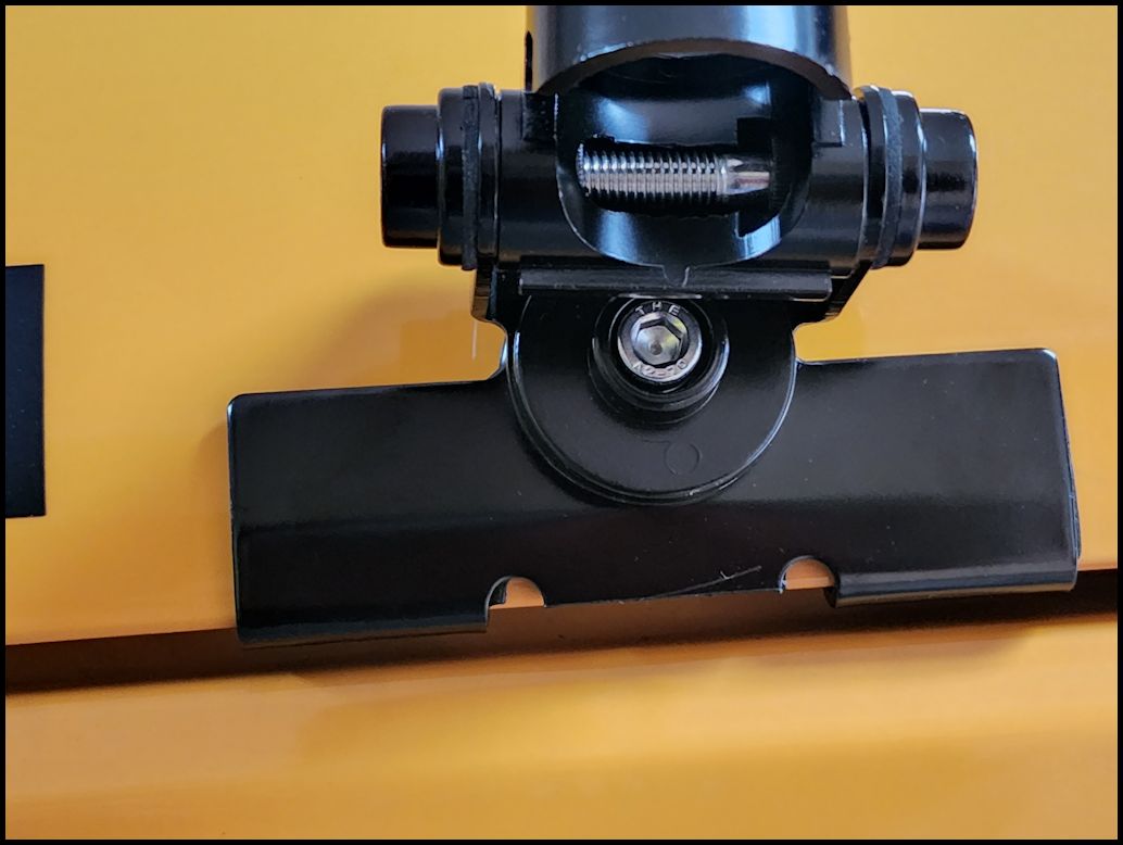
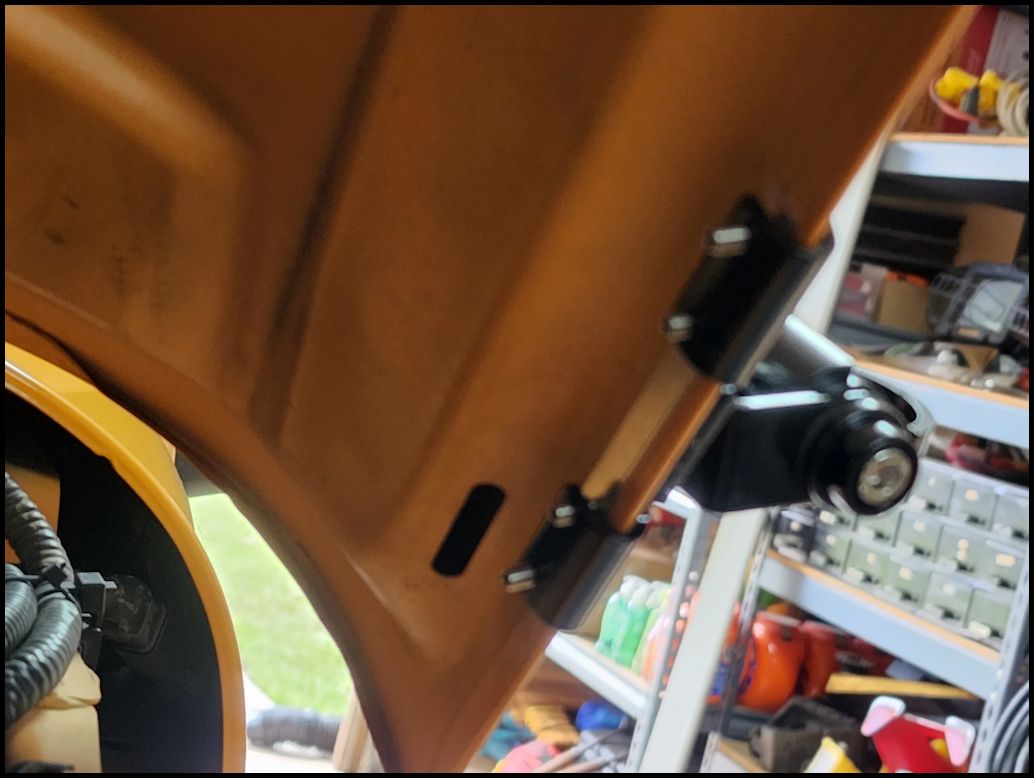
| Position the mount where you want to locate it. I decided to place it on the outside edge of the driver side hood lip. I did think about placing it in the center of the hood, but if I were to fold the windshield back I would most likely destroy the antenna and dent the cowl between the windshield wipers. Place the metal strip between the allen screws and the hood. This just helps destribute the clamping pressure of the allen screws over a larger area and hold the rubber backing of the outer flange against the paint and hood. Tighten the four (4) allen screws with the supplied small allen wrench. |
 |
 |
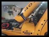
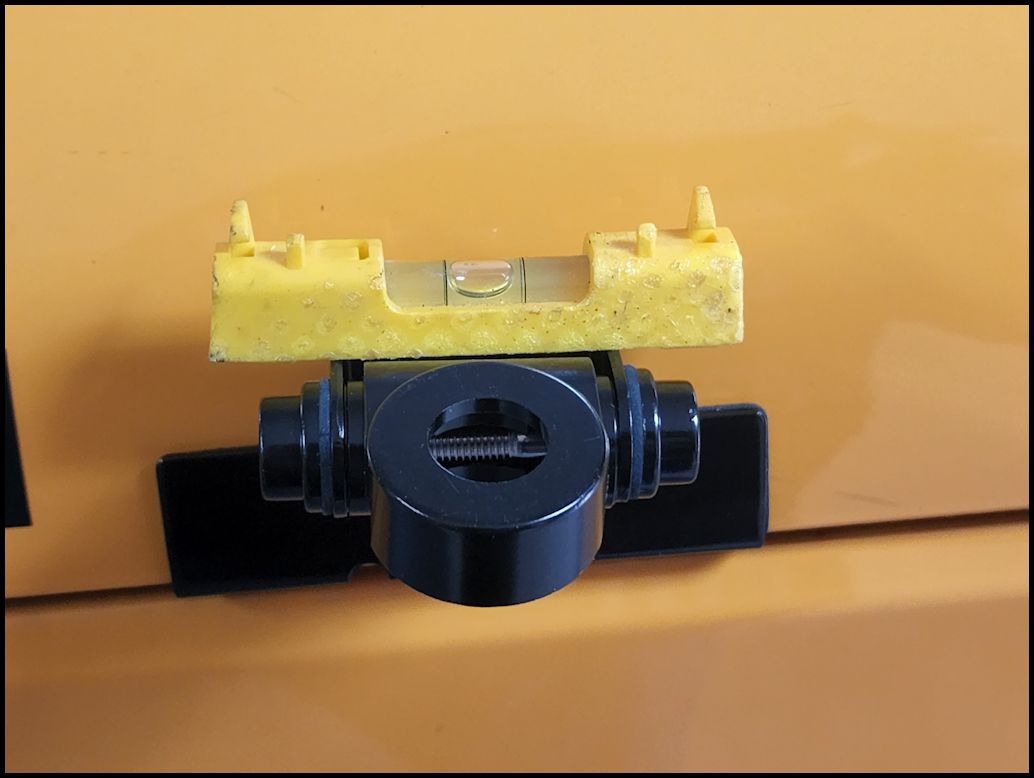
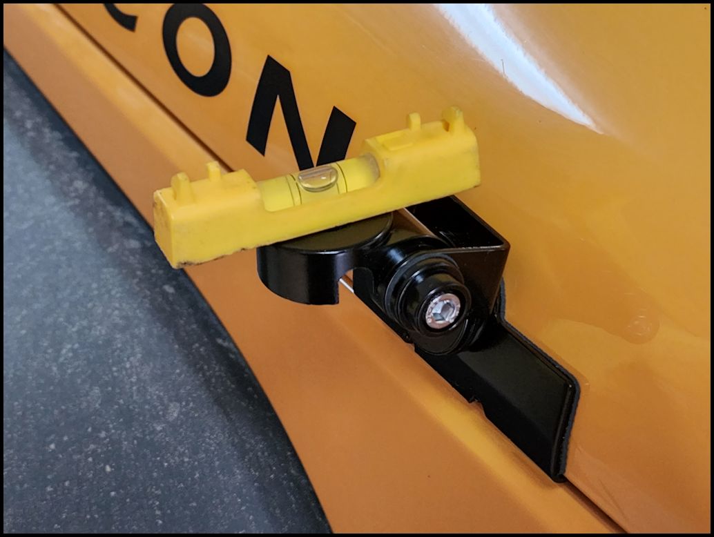
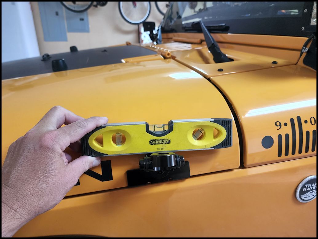
| Close the hood and level the mount front to back using a small level. Once you have this level, tighten the large allen bolt below the mount with the supplied large allen wrench. I really don't know if you have to be this precise about it, and in retrospect I did do this without having the Jeep loaded down with my normal gear in the back so I am higher in the back than normal. |
 |
 |
 |
| Level the mount left to right using a small level. Once you have this level, tighten the two (2) allen bolts with the supplied large allen wrench. You probably could just install the antenna and eyeball the position and then tighten the bolts. I'm just being a little OCD at the moment. |
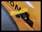 |
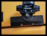
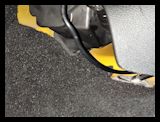
| The antenna does clear the windshield frame with the hood all the way back. You can mount the antenna almost all the way to the end of the hood. |
 |
|
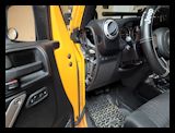
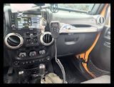
| Mounting the Head Unit (Option 1): |
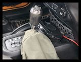
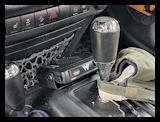
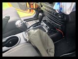
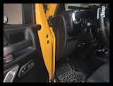
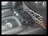
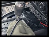
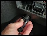
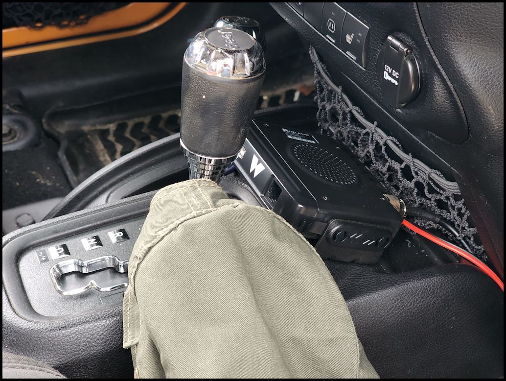
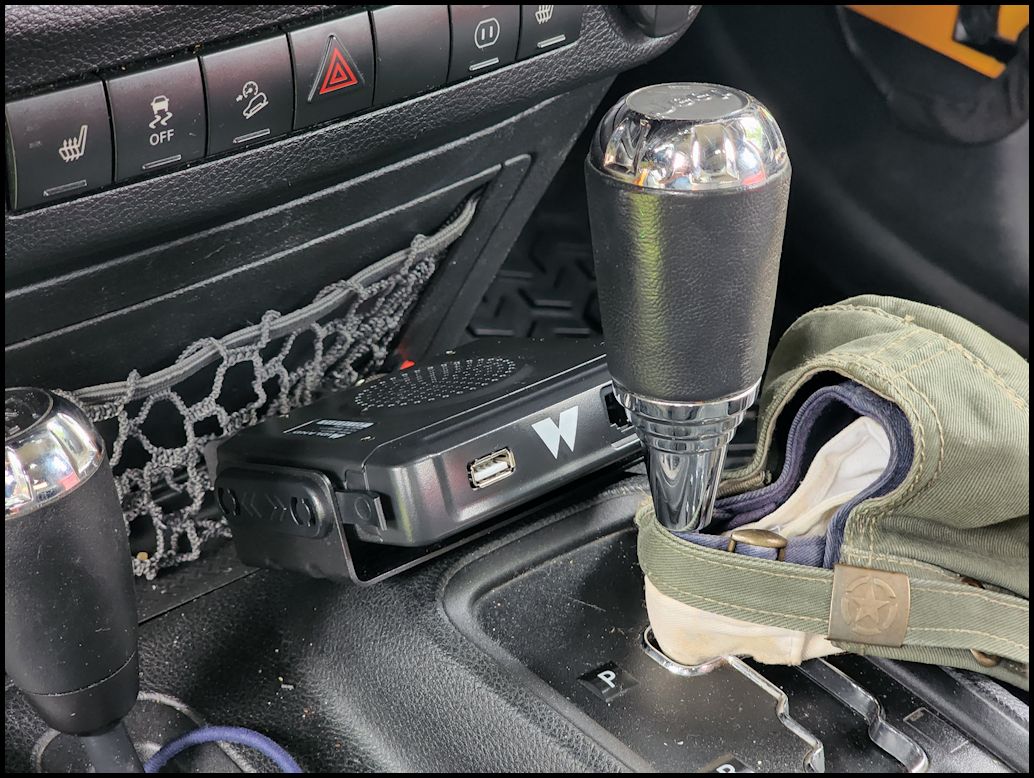
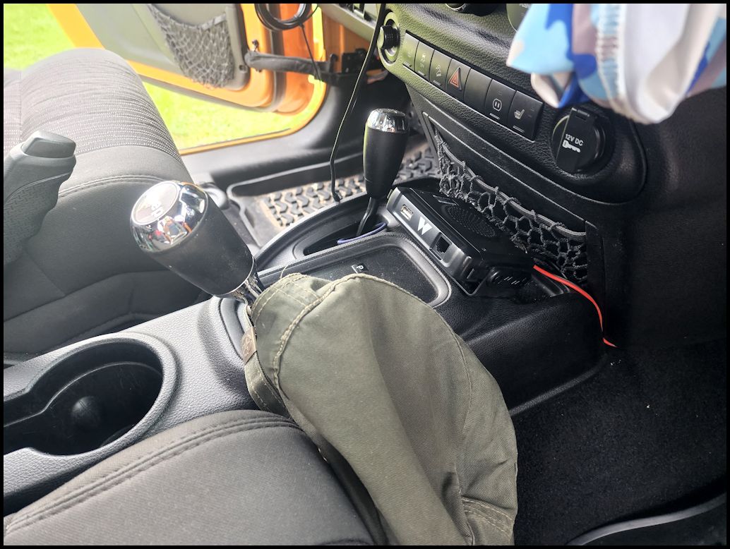
| Trying to figure out where to mount the head unit can be interesting. A few locations came to mind. I could have mounted it on either side of the center console, but didn't really want anything right next to my leg. Some people are fine with it in this location. I could have mounted it under the steering column on the removeable panel, but didn't want to bang my knee against it, or have the mic cable hanging down where I might snag it. It could have gone under either of the seats, but I didn't feel like pulling the seat just to install a radio head unit. Behind the glove box was another option, but I really didn't like any of the fitment back in there. I actually use my center console and glove box to hold stuff, so putting it in there was out. I decided to mount it right in front of the shifter. This does give a little protection from someone just sliding it out when the vehicle is parked. Eventually I may move it up to the overhead molle panel and then run a jumper down from the unit to a connector under the glove box. |
| I test fit the unit in the area to make sure it didn't interfer with the shifter and that the shifter didn't interfere with the mic cable. I decided to moun the speaker pointed up to see if I could get better sound out of it. The wind noise driving on the freeway with the windows down drownds out the speaker, but otherwise with the windows up or going slow its pretty loud. |
 |
 |
| Make sure you block the tires. Shift the transmission selector to drive to give you room to work in front of the selector knob. |
 |
| Remove the head unit from the flip-frame detachable mount (the mounting bracket). To get the radio out you need to pull the two (2) tabs out while simultaneously pushing the radio forward in the mount. |
|
|
| Position the bracket with it centered on the transmission selector and screw in the two supplied screws with a phillips screwdriver. I installed one screw and then reinstalled the head unit to make sure that I had positioned the bracket properly. |
 |
 |
| Don't reinstall the head unit yet. You will need to screw in the antenna cable and make sure you have enough length of power cord to reach the connector properly. |
 |
| |
| Mounting the Head Unit (Option 2): |
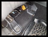
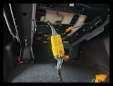
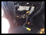
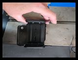
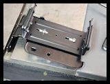
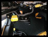
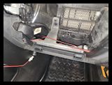
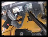
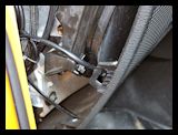
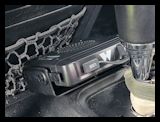
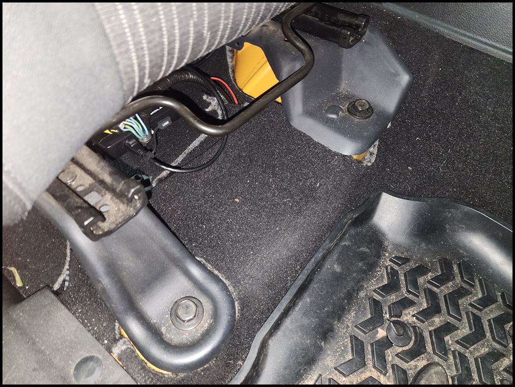
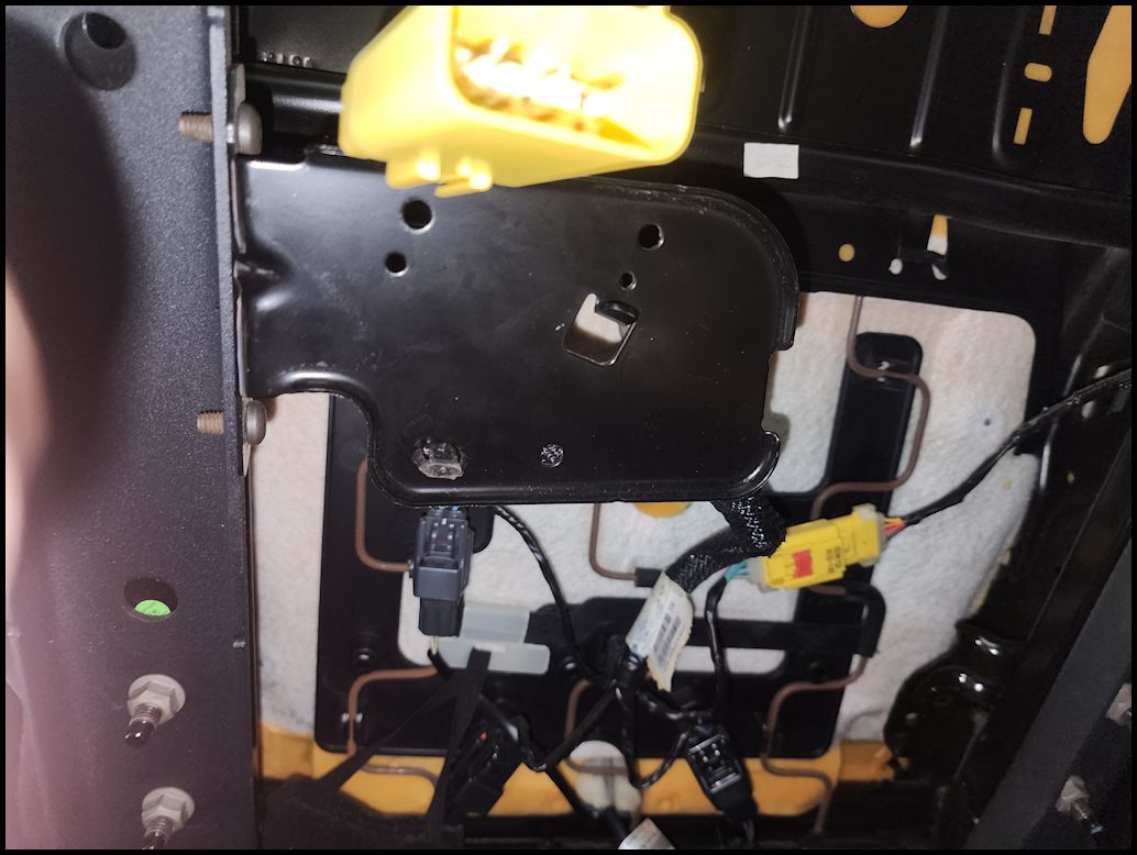
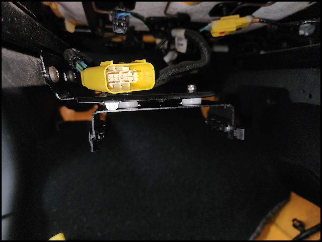
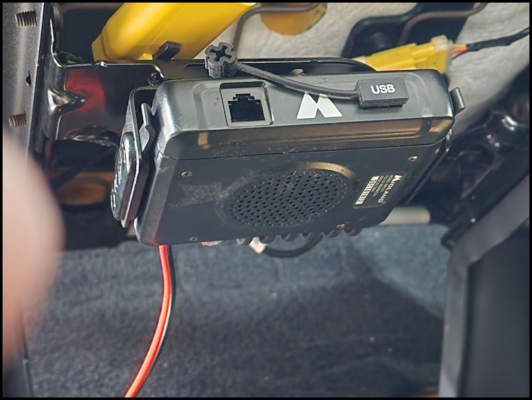
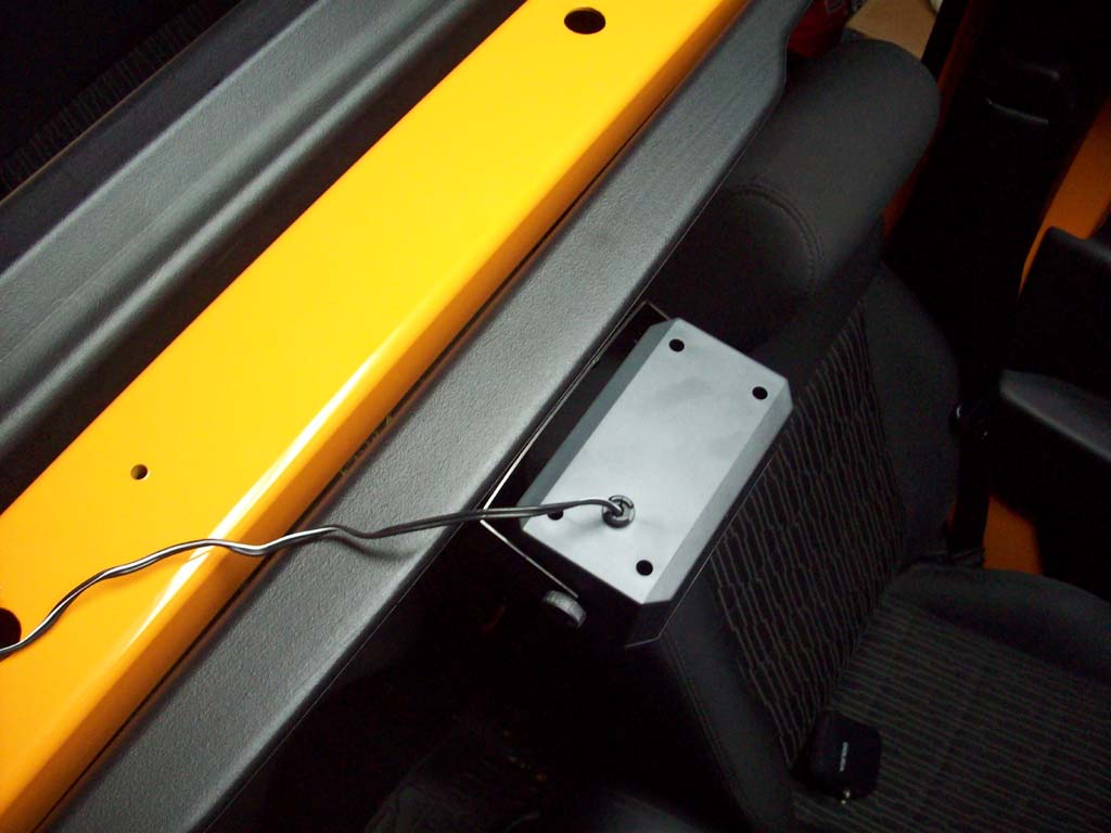
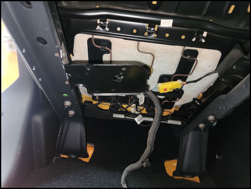
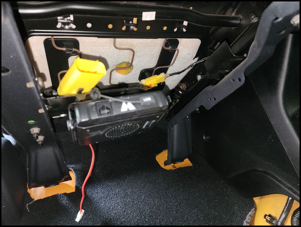
| Another option for a more hidden mount is to place it on the bracket located underneath the passenger seat. This bracket typically holds the wiring harness that provides power to the seat heaters and signal leads for the weight sensors. If you have side air bags you will also find that connector here. |
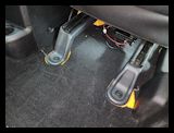
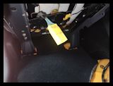
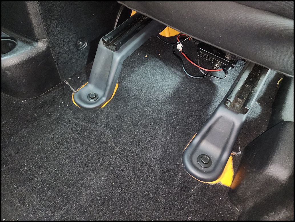
| 1. Remove the 4 bolts holding the seat to the floor. You will need a 18mm Socket and a 1/2" ratchet. These bolts are in extremely tight and may have locktite on them from the factory. You may be able to do this without taking the seat bolts out. |
 |
 |
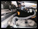
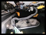
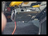
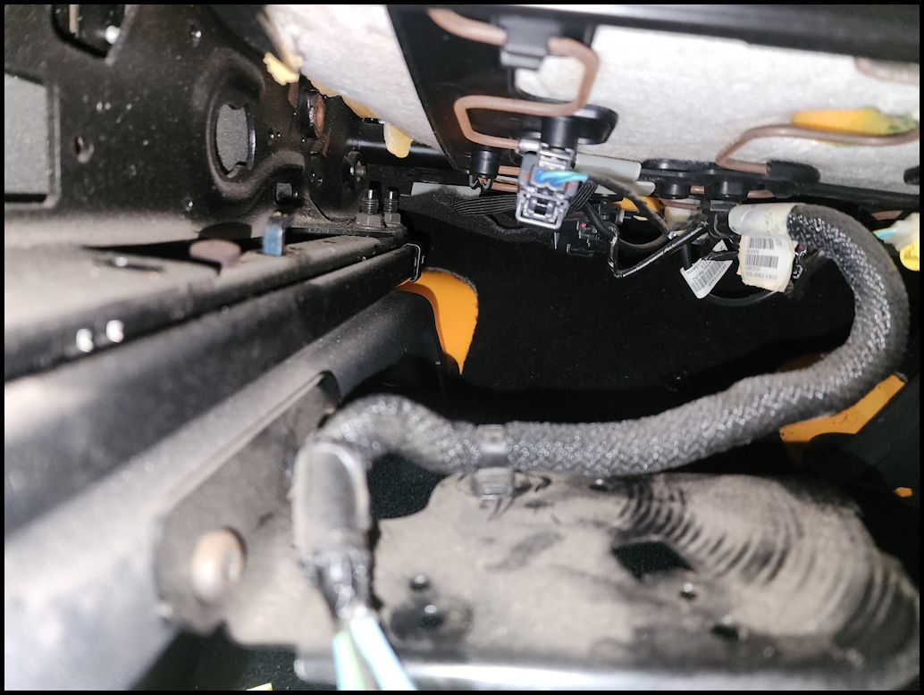
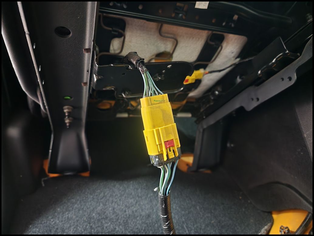
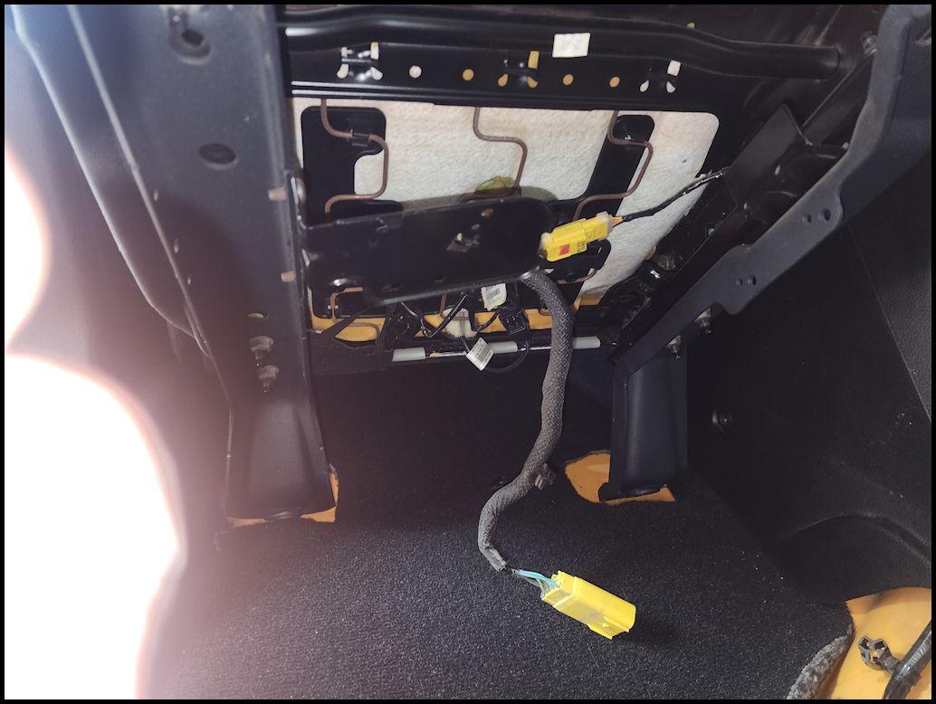
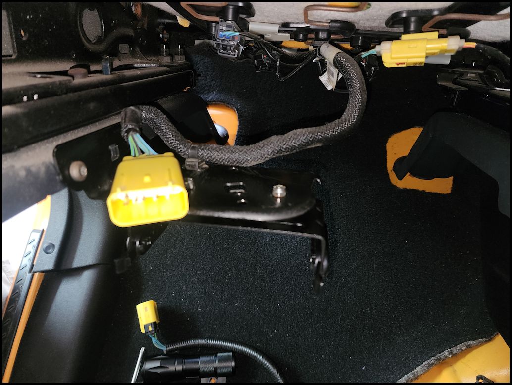
| 2. Tilt the seat back and unhook the wiring connector from the bracket. It is attached to the bracket by a couple of christmas tree push connectors under the connector and another that holds the wiring to the plate. |
 |
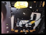 |
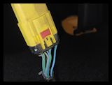
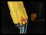
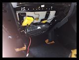
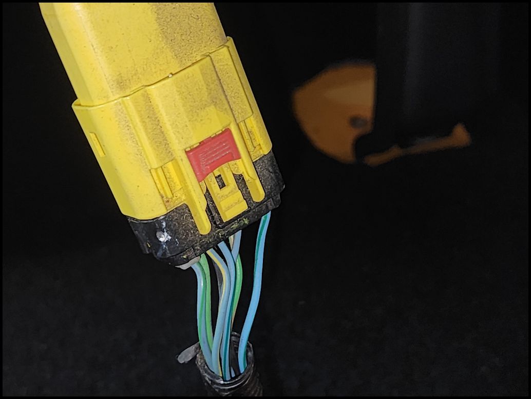
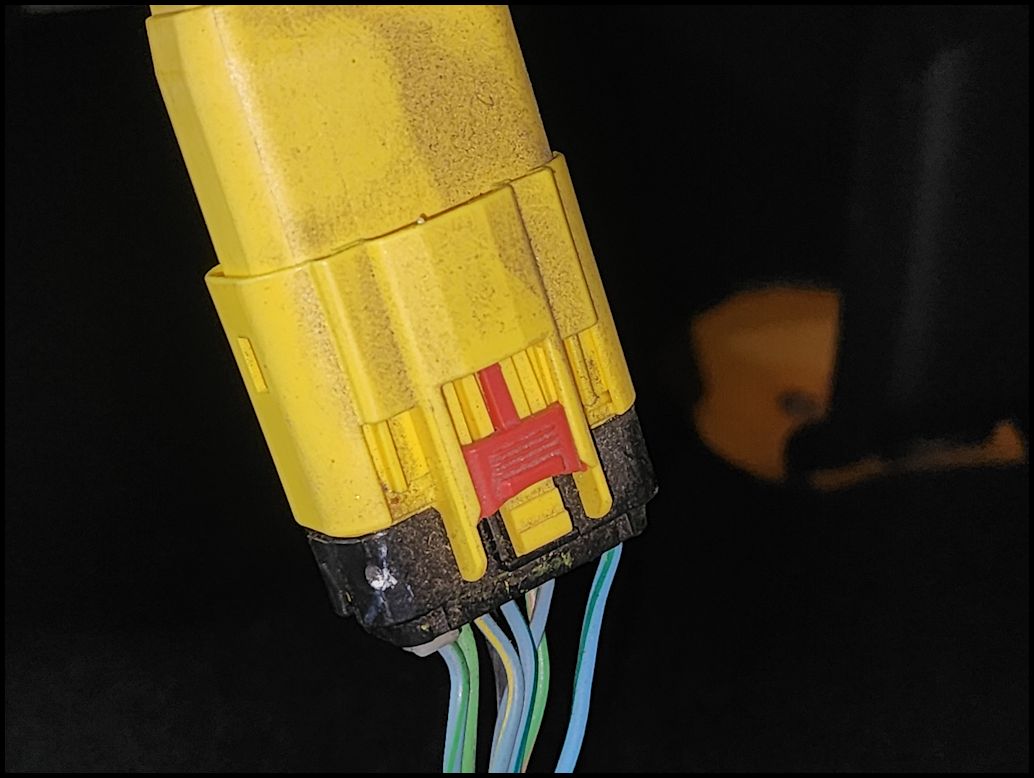
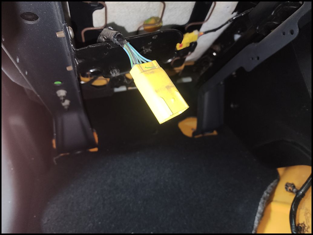
| 3. If you have side air bags you will need to disconnect the battery and wait a while for the charge in the system to dissapate. Airbags are scary. Disconnect the yellow connector. Pull down on the red lock tap and then press the tab to release the connector. |
 |
 |
 |
 |
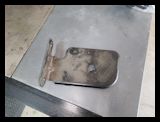
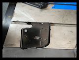
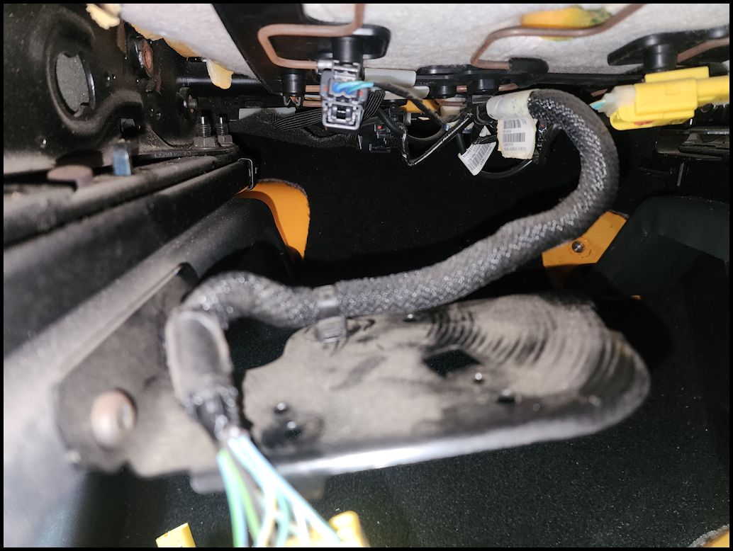
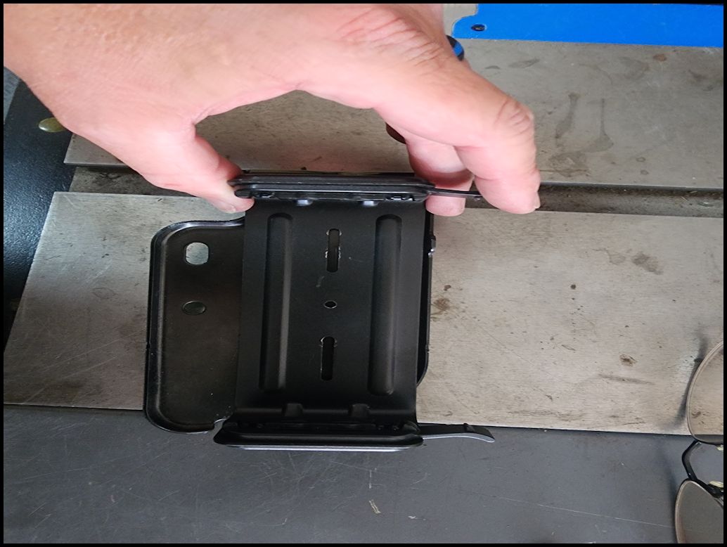
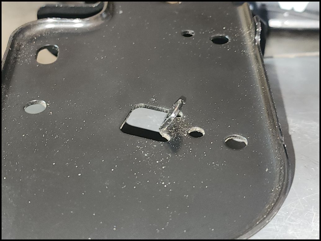
| 4. Move the harness out of the way. Use a 1/4" ratchet and T30 Torx socket and remove the two screws holding the mounting plate in position. I did try this with a Torx screwdrive, but could not get enough force to turn the screws. Once they start to screw out, you may be able to get them out the rest of the way using the torx screwdriver. My screws had blue locktite on them. |
 |
 |
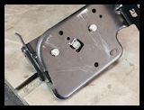
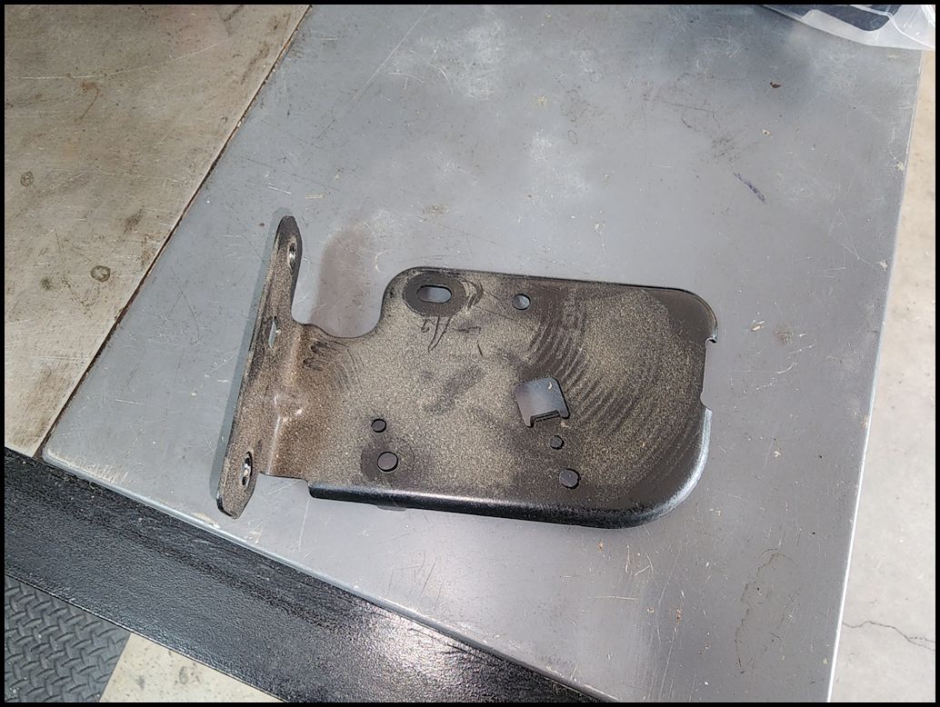
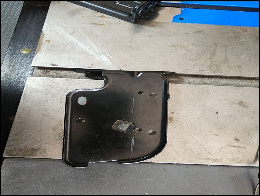
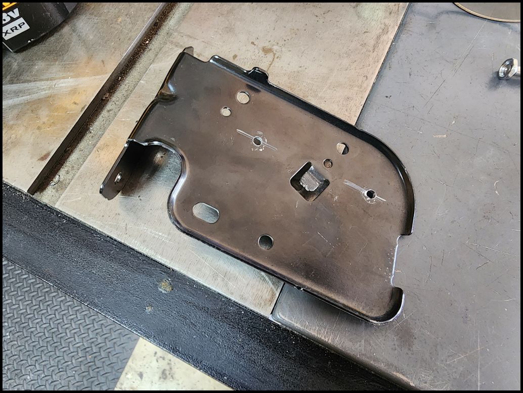
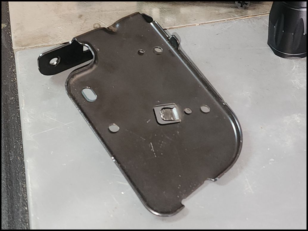
| 5. Remove the mounting plate from the Jeep. Put the screws somewhere safe, I recommend screwing them back into the seat bracket. |
 |
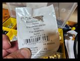
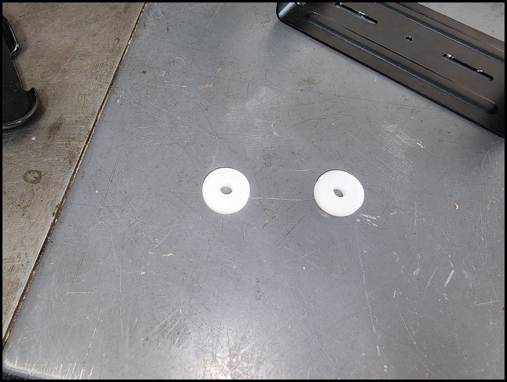
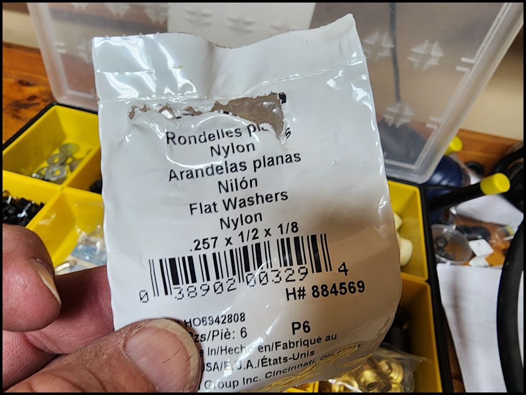
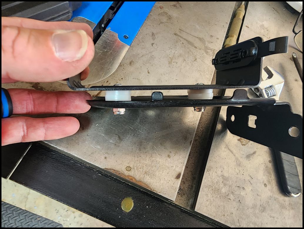
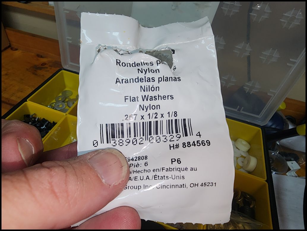
| You will need 6 of the nylon flat washers to act as spacers. You will need about 3/8" of space between the plate and the mounting bracket for the MXT275. |
 |
 |
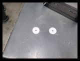
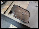
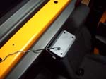
| 6. Line up the MXT275 bracket on the plate. I lined it up so that it didn't interfer with the mounting points of any of the connectors that are mounted to the top of the plate. I lined up the edge of the bracket with the outer edge of the mounting plate where it curves. Mark where you are going to drill. |
 |
 |
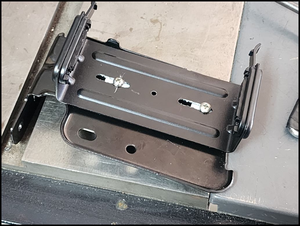
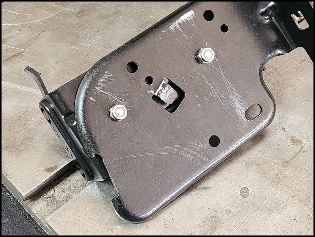
| 7. Drill holes for the size of the screws that you are going to use. I used some M8 bolts (I believe) that were just a little more than 1/2" long and some nylon lock nuts. I used three (3) of the nylon spacers on each side to space the MXT275 bracket down enought to clear all the mounting for the wiring connectors. Just make sure you place the bracket on facing forward. |
 |
 |
 |
 |
| 8. Reinstall the mounting plate onto the seat bracket. I was able to use a T30 torx screwdriver to screw these in. Use a 1/4" ratchet and T30 Torx socket to tighten up the screws. |
 |
 |
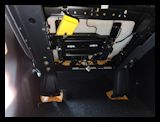 |
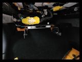
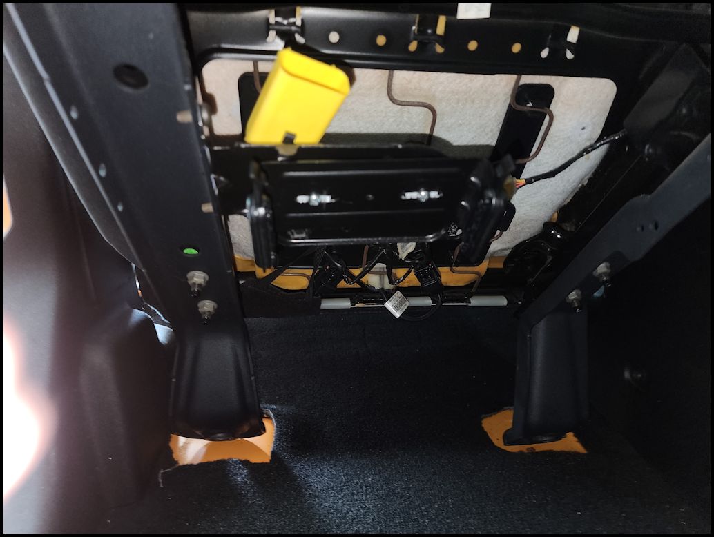
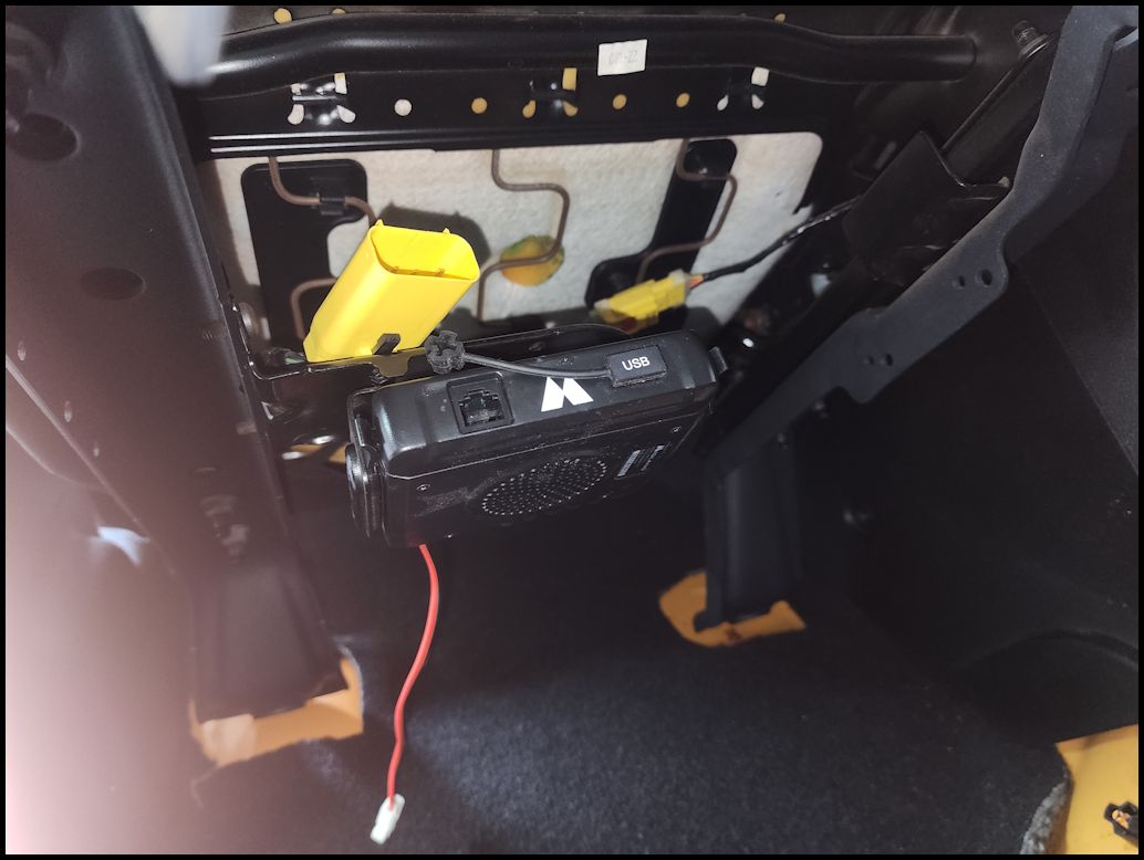
| 9. Reconnect the wiring harness and slide the red lock tab back into place. Slide the MXT275 base unit into the bracket. |
 |
 |
| 10. Tilt the seat back down and into position. You may need to slide one of the rails to get this to realign with the bolt holes. Install the 4 bolts holding the seat to the floor. You will need a 18mm Socket and a 1/2" ratchet. |
| |
| Running the power cable to the battery: |
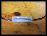
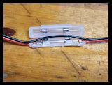
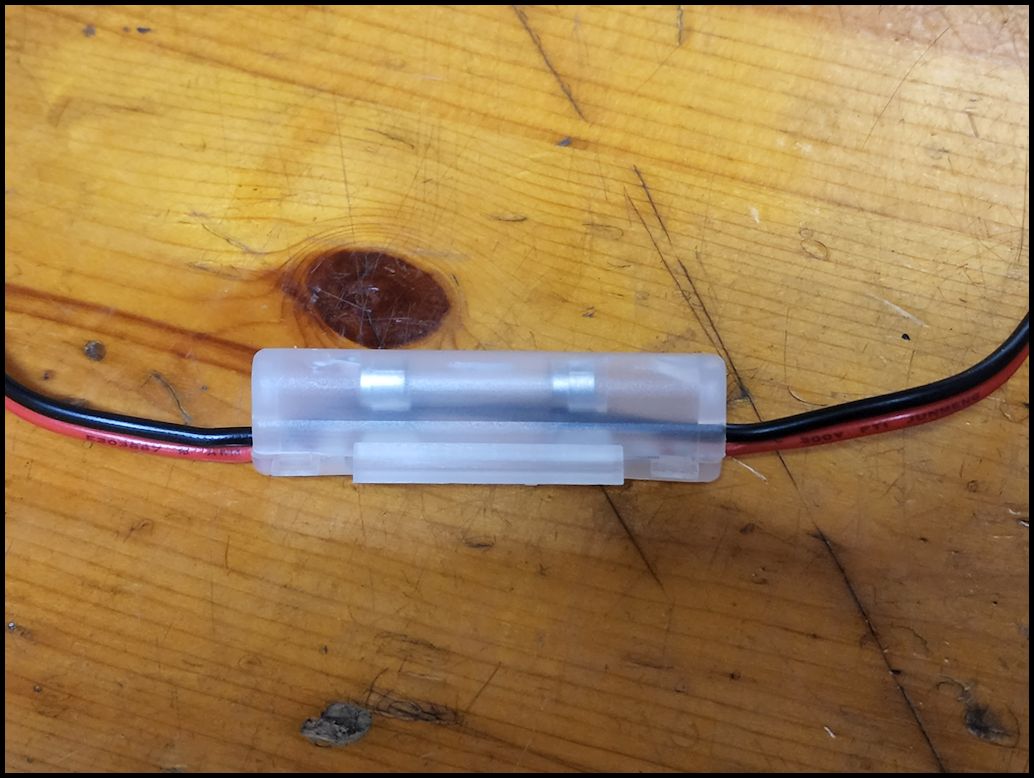
| If you are using this as a portable unit, or do not want to hard wire the radio into your electrical system you can just use the power adapter as it comes from Midland. There is a fuse holder on the wiring with an extra fuse inside. Additionally, the power adapter tip unscrews to reveal a second fuse inside. |
 |
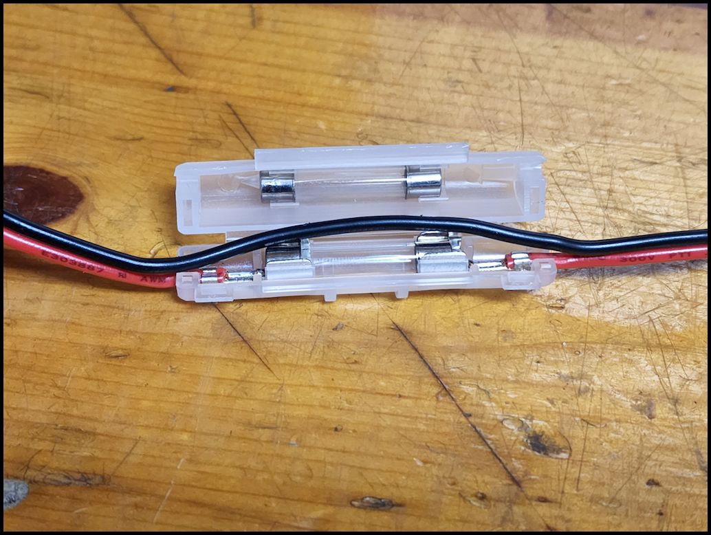
| The fuse holder is difficult to get open, but it does include an extra fuse. It took some prying with fingernails to get it to open. |
 |
 |
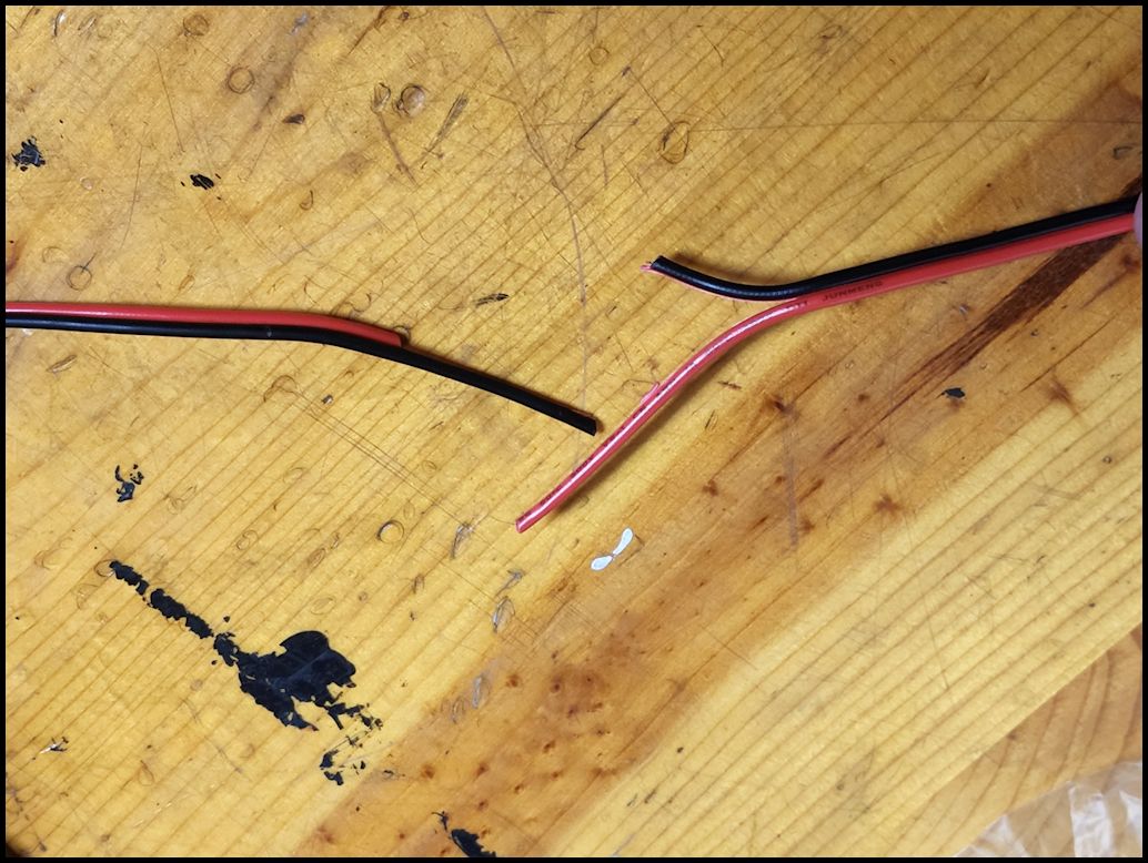
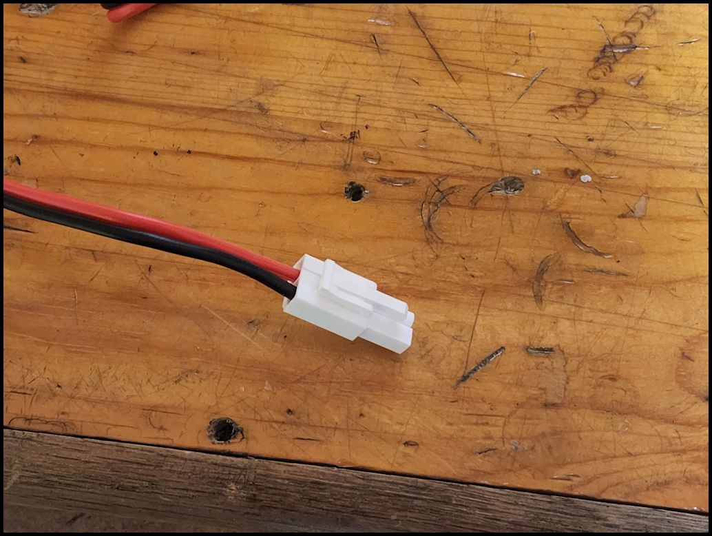
| Cut the power adapter side off of the cable. I would leave about 4-6 inches of cable just incase you want to wire it back up later to use as a portable unit. |
 |
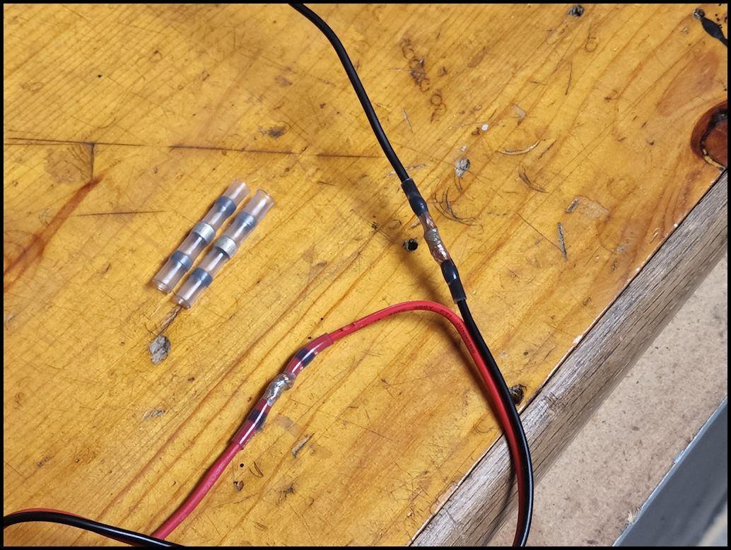
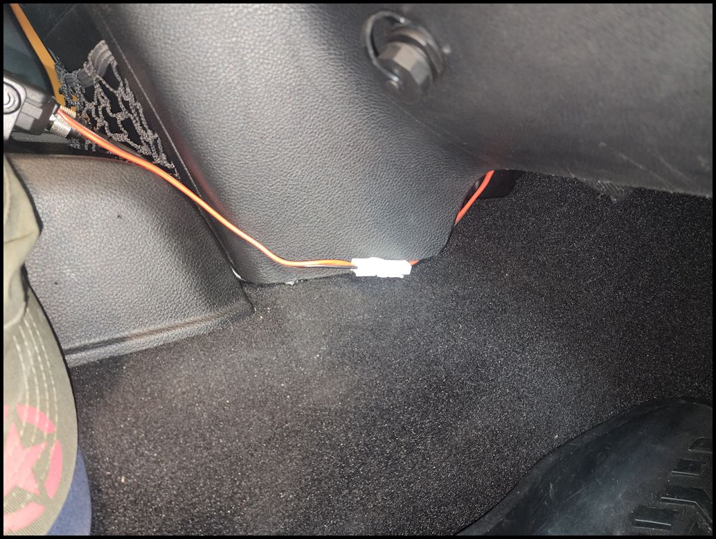
| Cut and strip the ends of the power cable and the extension you will be wiring in if you are going to the battery. You can skip this if your wiring it to another source within reach. I use soldered heat shrink connectors when connecting wires, it gives a nice solid waterproof connection. I also offset the wires so that the conectors lay flatter along the cable. |
 |
 |
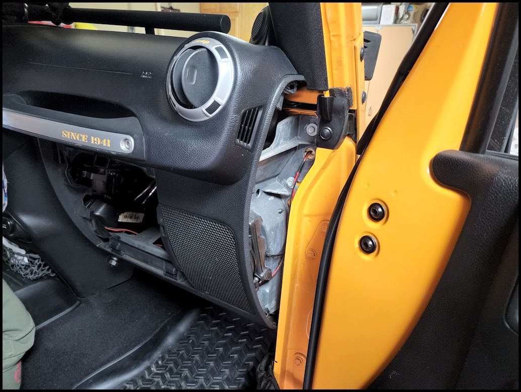
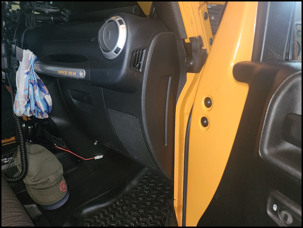
| Remove the trim panel from the passenger side of the dash. You can use a trim removal tool, or a flat tip screwdriver. The panel is just clipped in. Make sure all the clips come out with the panel. |
 |
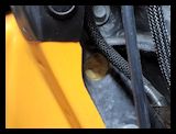
 |
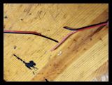
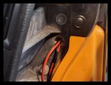
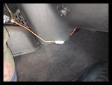
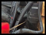
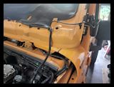
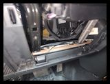
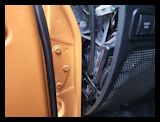
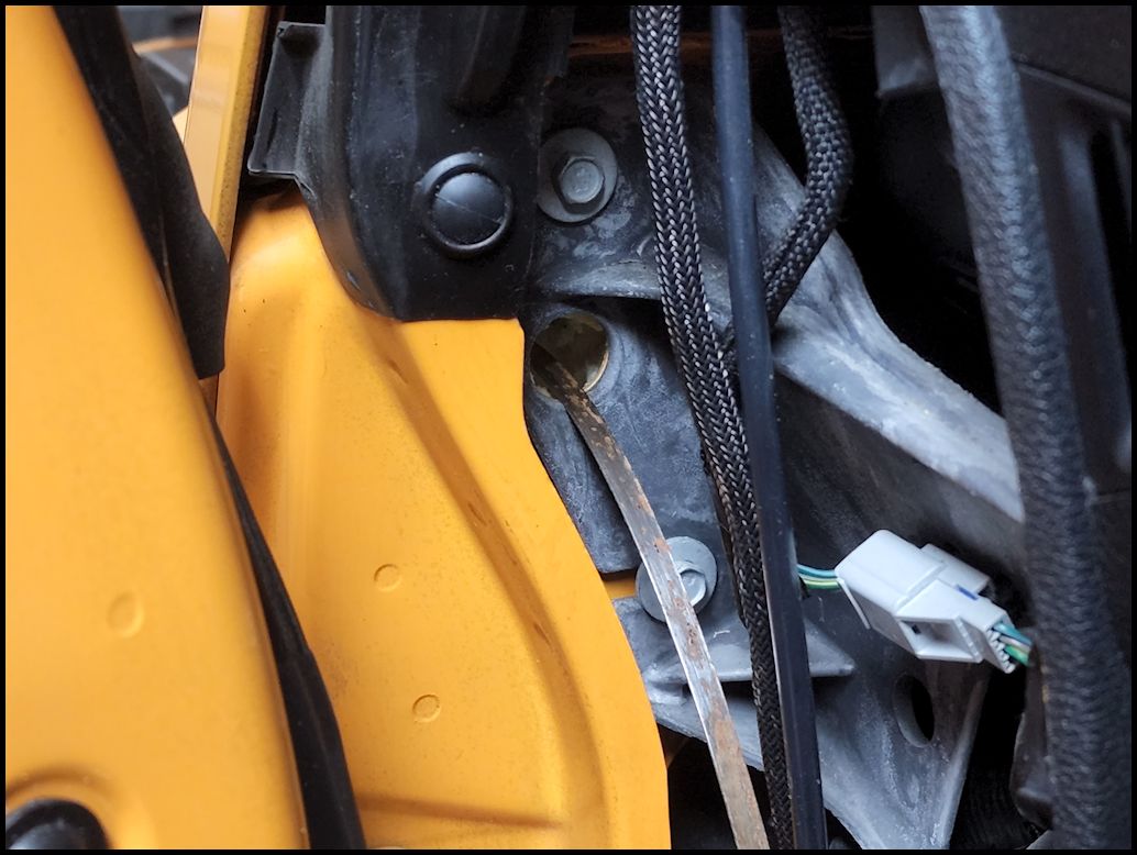
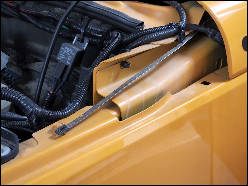
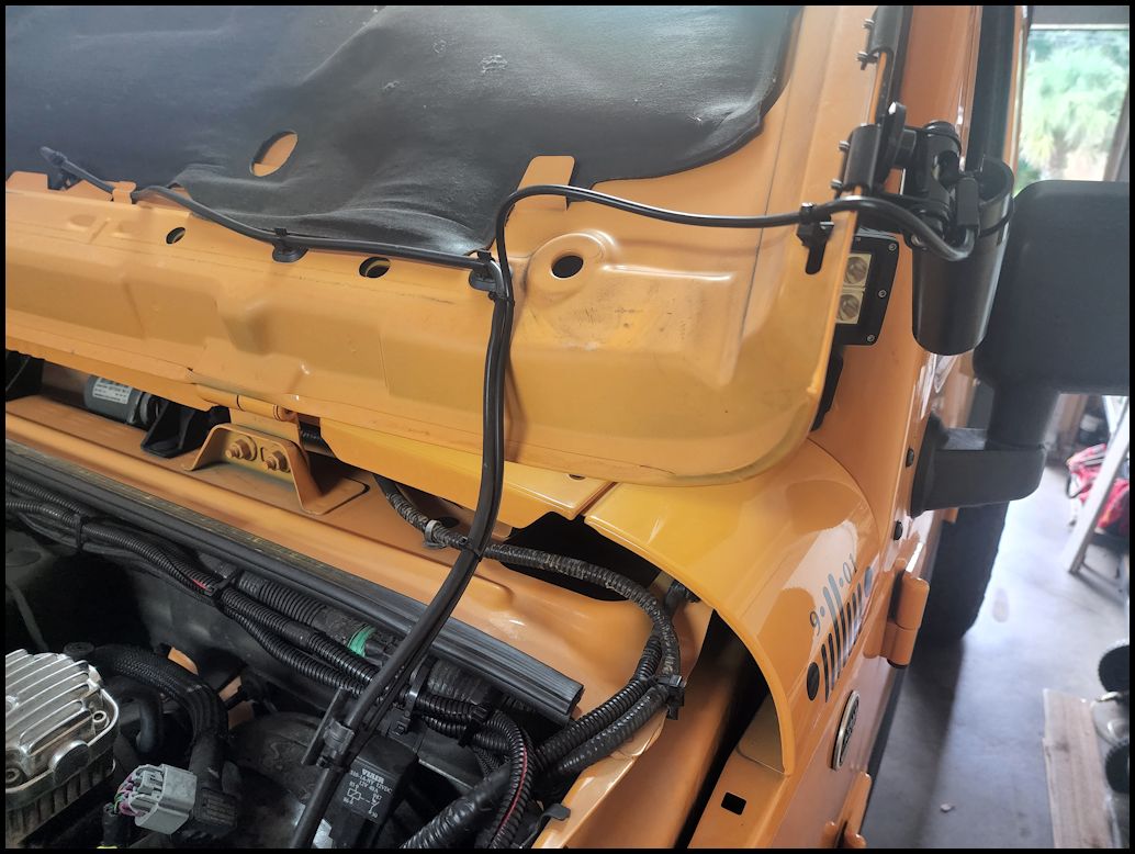
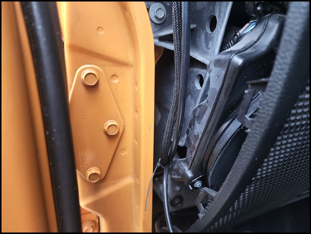
| There is a foam filled hole in the firewall that you can use to pass wires through into the engine compartment right along the hood line. I already had a hole poked into the foam to run some wiring, so it was easy to fish the new wires through to the other side. If you are running wires for the first time you will need to poke the foam out with a screwdriver and then use a fish tape or coat hanger to get the wires through. |
 |
 |
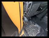
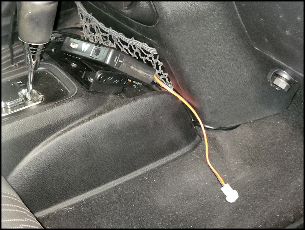
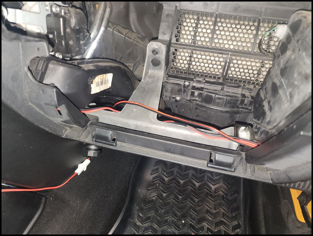
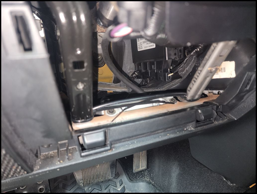
| I routed the power wires underneath the speaker and then across the lower dash bar underneath the glove box. Then I pulled enough wiring to go behind the center console and out just behind the GMRS head unit. Leave enough slack to connect the lead from the head unit to the power lead. |
 |
 |
 |
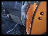
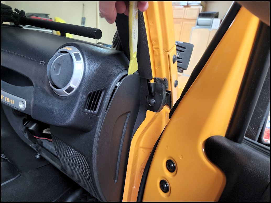
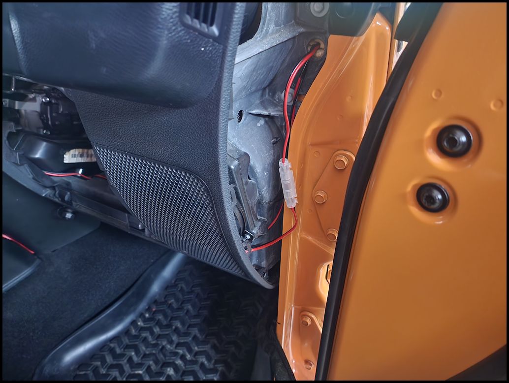
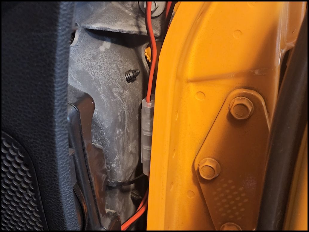
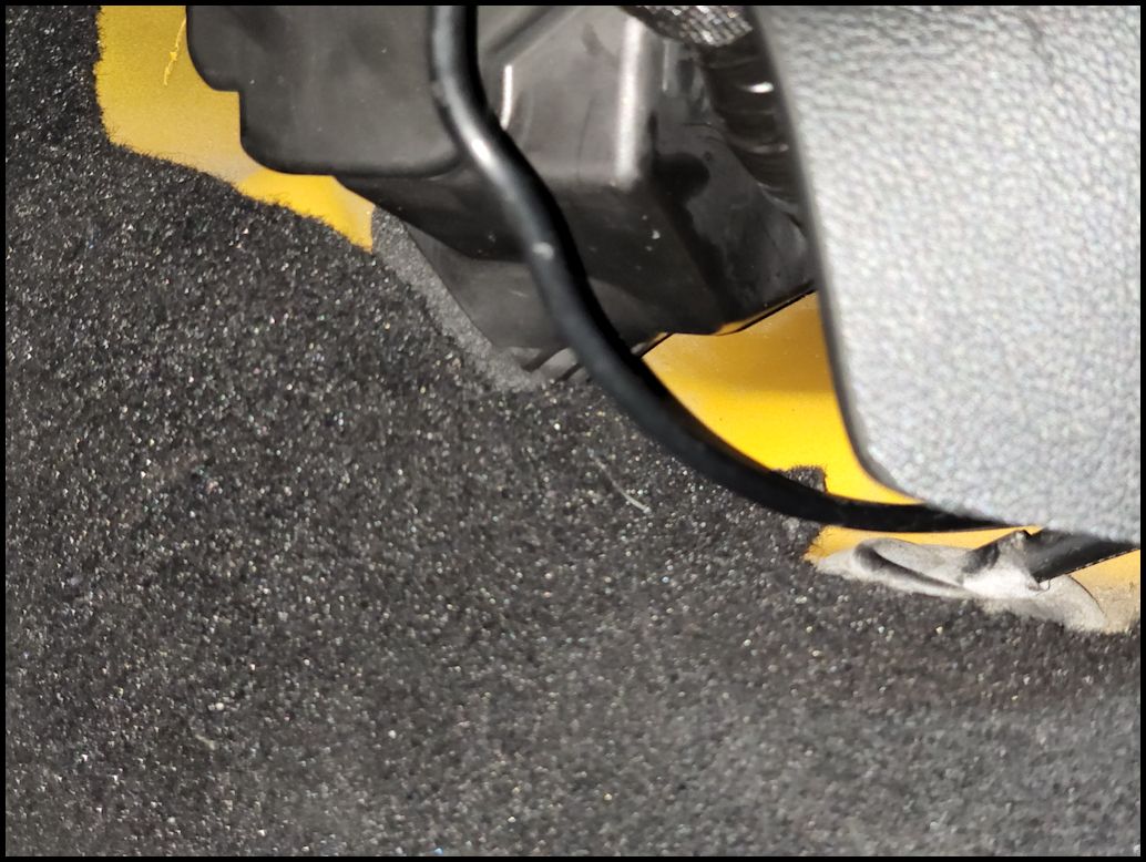
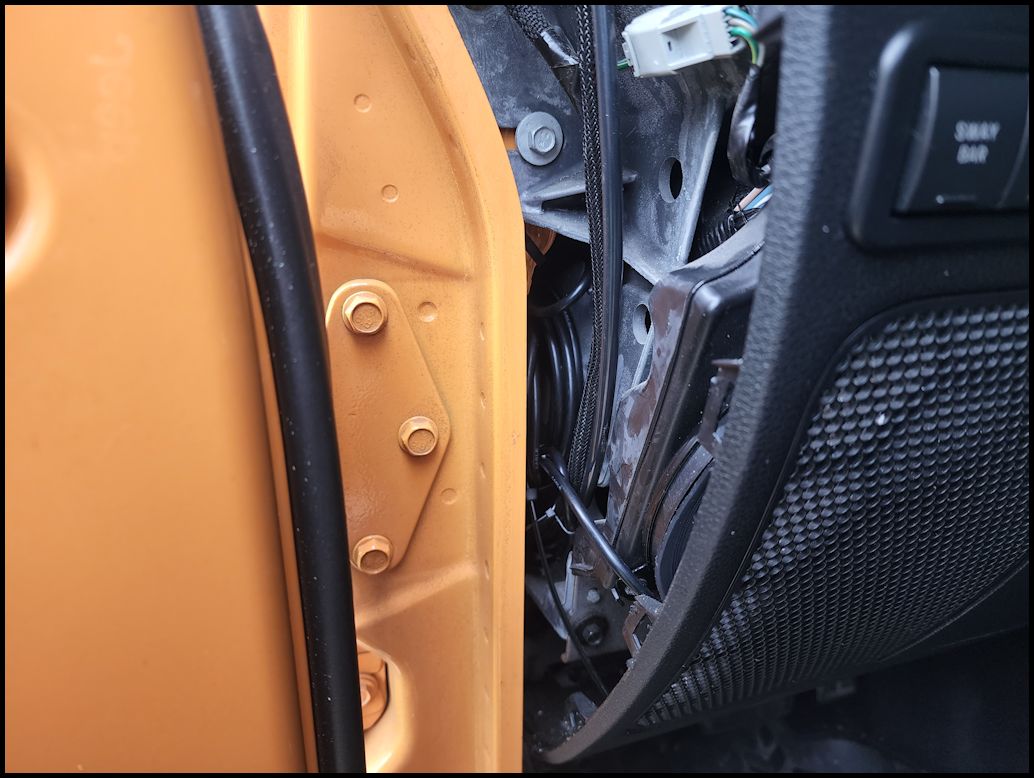
| The fuse holder ended up being along the side of the dash. I made sure to leave enough wire to pull the fuse holder out to check or replace a blown fuse. I tucked it back in behind the door frame out of the way. There is enough room back there for it to fit snugly out of the way. Reinstall the side panel. |
 |
 |
 |
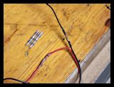
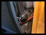
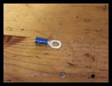
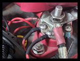
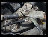
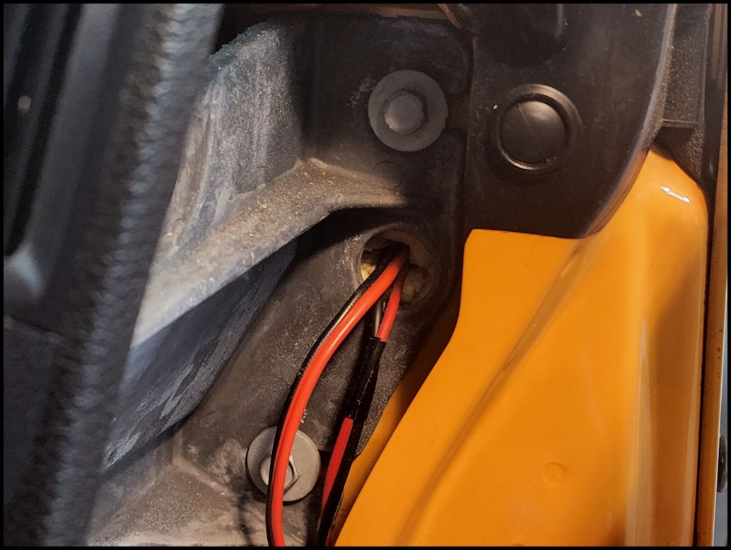
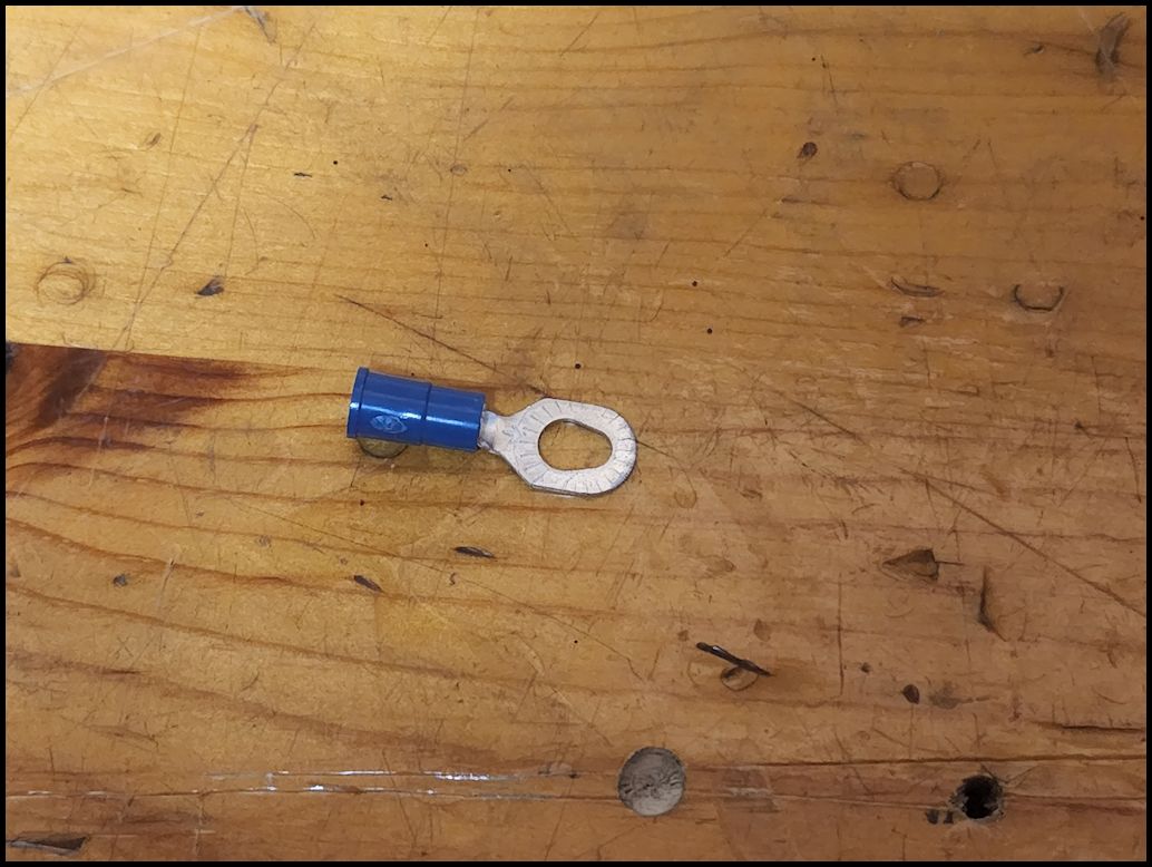
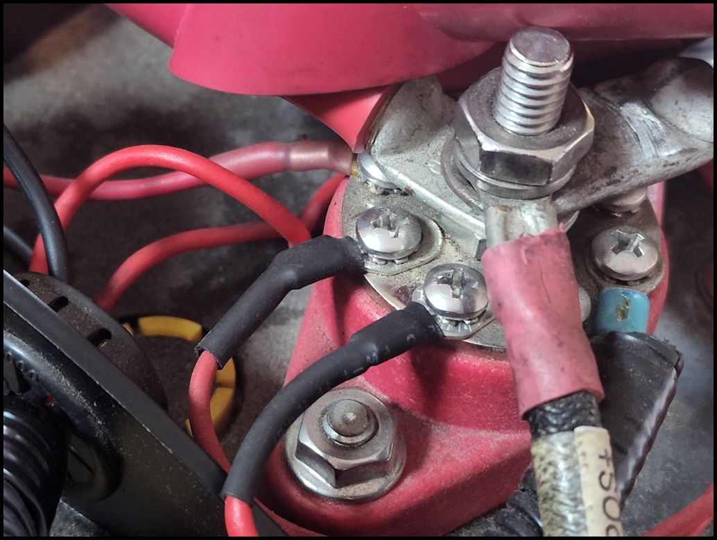
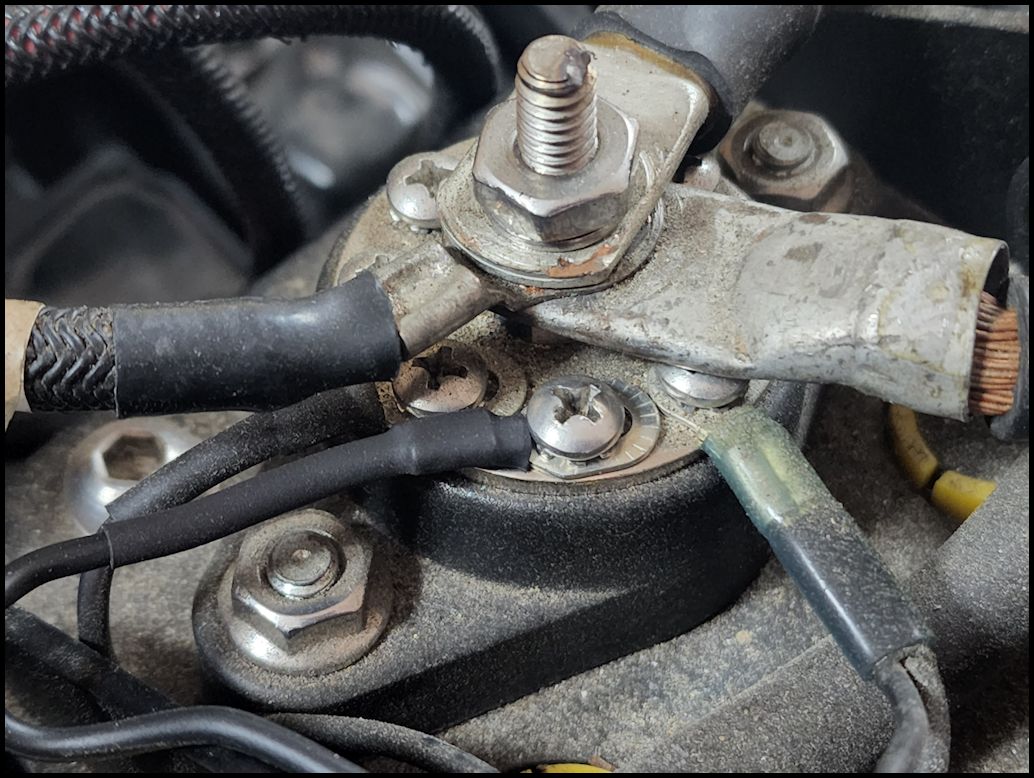
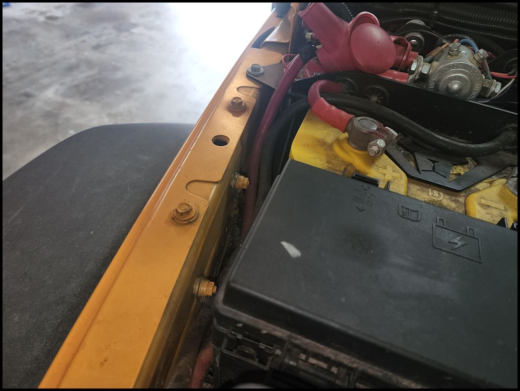
| Cut the wire to length and install some ring connectors (size for your application) on the ends so that you can connect to the battery. Heat shrink to protect the connection. I connected to both the positive and negative, but you can connect to the postive and a chassis ground on the side. |
 |
 |
 |
 |
| |
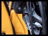
| Running the antenna lead: |
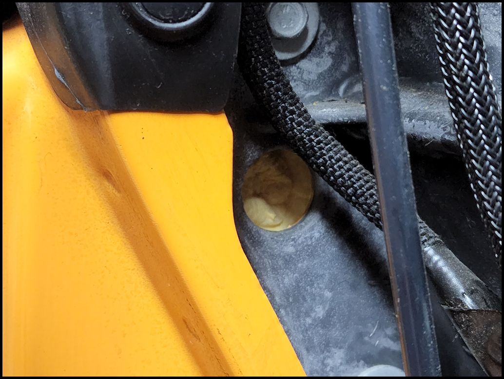
| Unless your mounted your antenna back by the tail gate you will pretty much need to come through the firewall and into the cab somehow. There are a couple locations that you can do this. One is using either of the access holes that we ran the wires through earlier, or if you have an automatic you can run the wires through the cover for the clutch master cylinder. You can use the access hole if you have the Midland antenna cable with the removeable end, otherwise you will need to either drill out the sheetmetal behind the hole, or use the clutch master cylinder cover. Either way most of the steps are the same. |
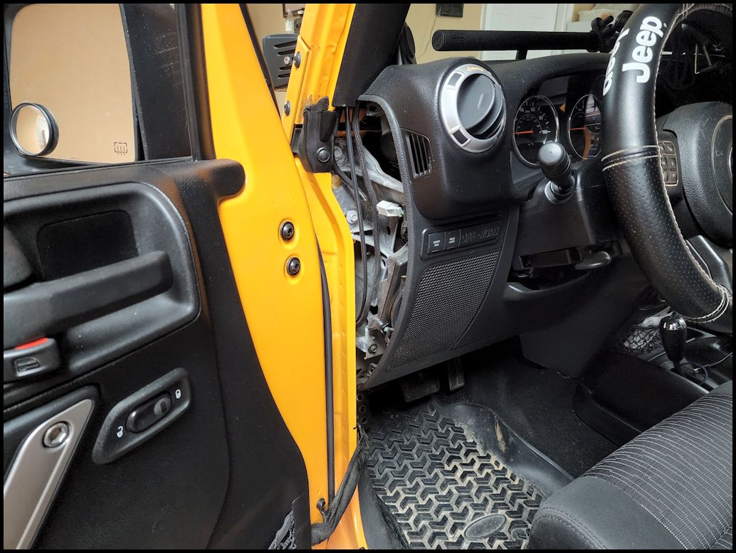
| Remove the trim panel from the driver side of the dash. You can use a trim removal tool, or a flat tip screwdriver. The panel is just clipped in. Make sure all the clips come out with the panel. |
 |
| Midland Cable with removeable end: There is a foam filled hole in the firewall that you can use to pass wires through into the engine compartment right along the hood line. If you are running wires for the first time you will need to poke the foam out with a screwdriver and then use a fish tape or coat hanger to get the wires through. |
 |
| Midland Cable with removeable end: Run a fish tape or coat hanger through the hole and into the engine compartment. |
 |
 |
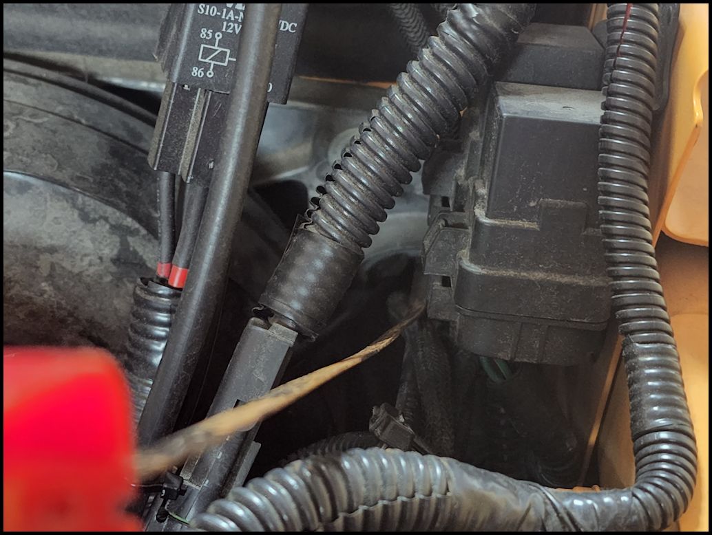
| If you are using a different cable with a non removeable PL-259 Connector end then you will need to run the fish tape or coat hanger in through the clutch cover from the engine compartment into the underside of the dash. You will need to contort your body and use a flashlight to look up under the dash to find the end of the fish tape or coat hanger. |
 |
 |
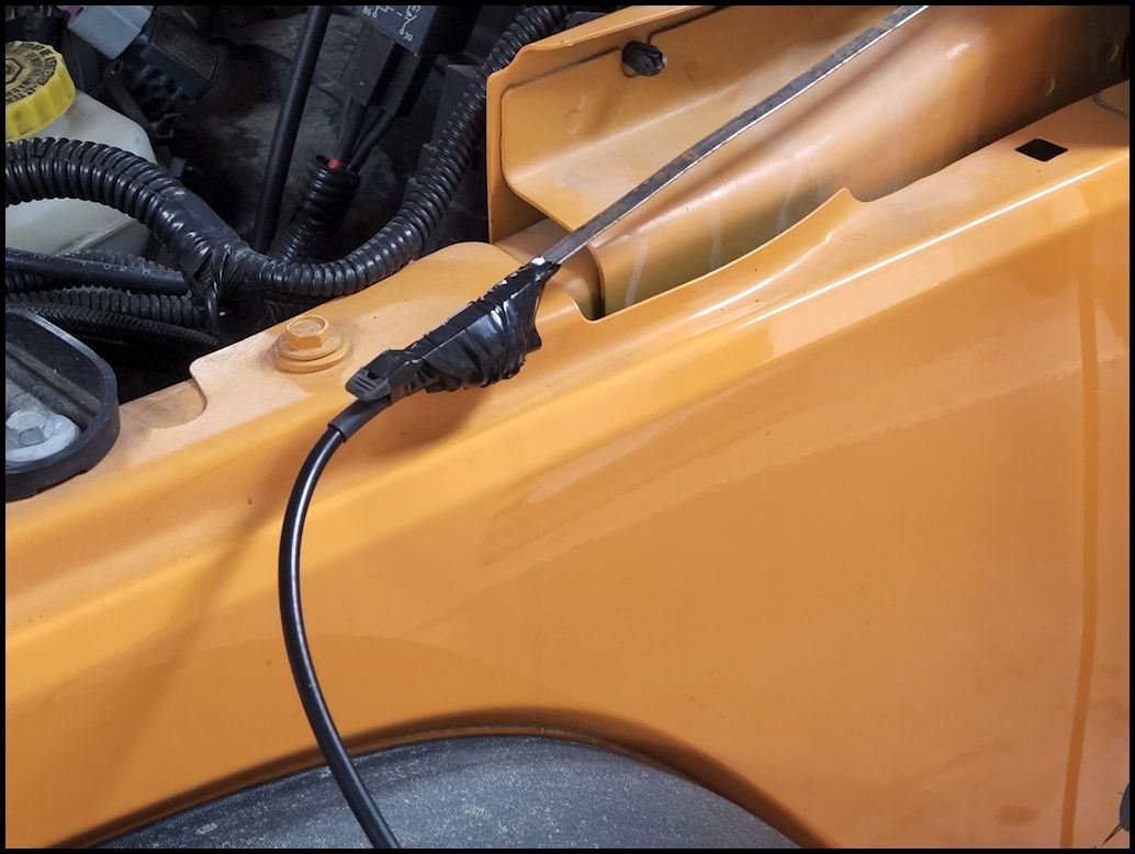
| Tape the end of the cable to the fish tape or coat hanger and carefully pull it through the hole. Take your time and slowly work the cable through the hole. |
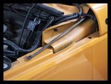
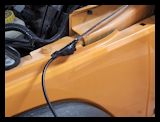 |
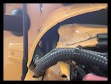
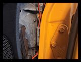
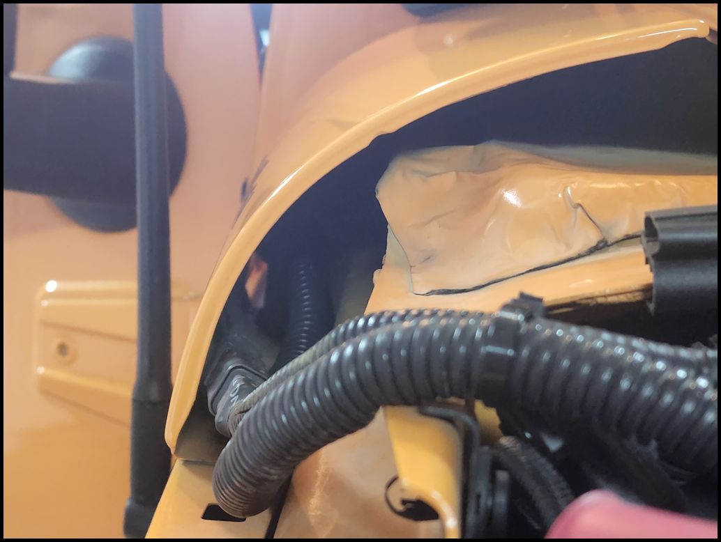
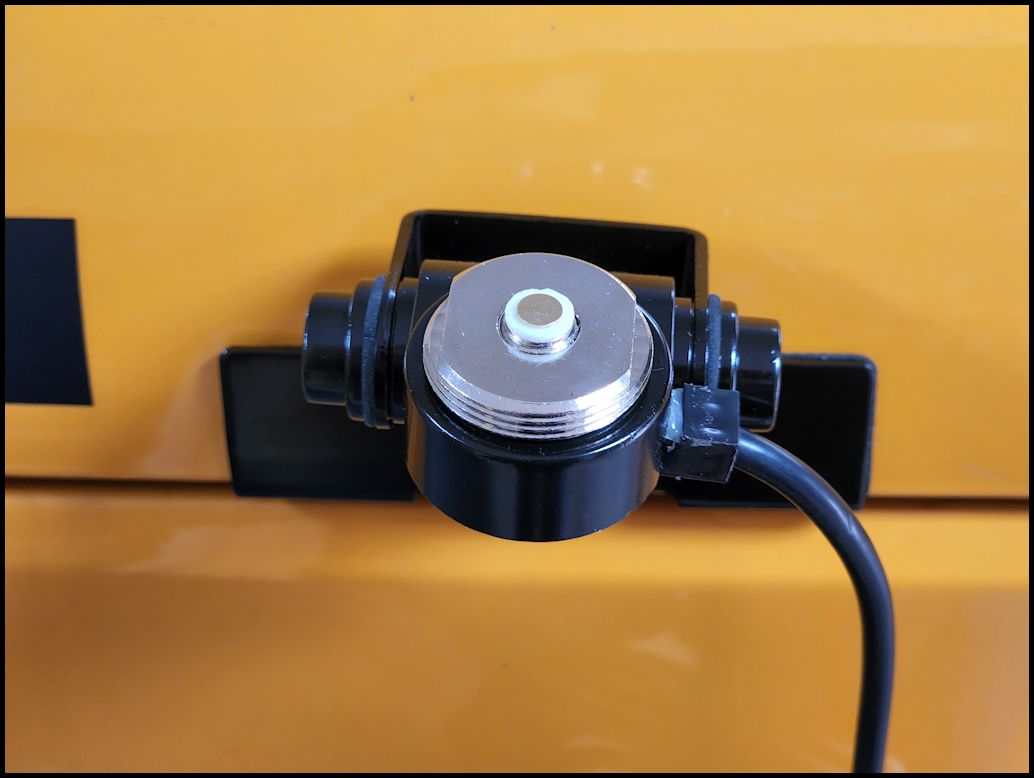
| Reinstall the antenna cable. I routed the cable back towards the firewall so that I didn't have a loop sticking in front of the antenna mount. Place the bottom up through the mount and thread the large ring down over the pin. Tighten finger tight plus about 1/4 to 1/2 turn with an adjustable wrench. I routed the cable underneath the edge of the hood and followed the washer hose from the hood back into the engine compartment. That way I had enough slack when I put the hood back. |
 |
 |
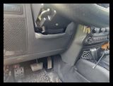
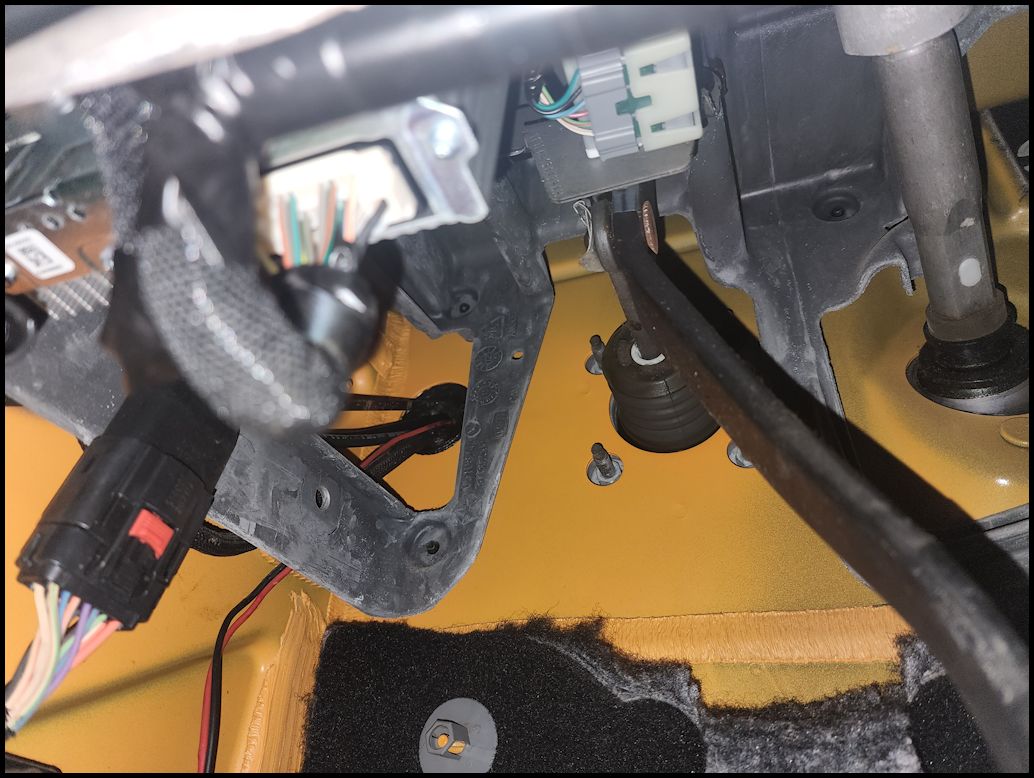
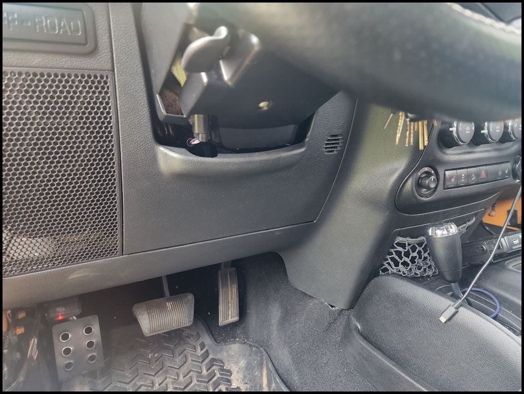
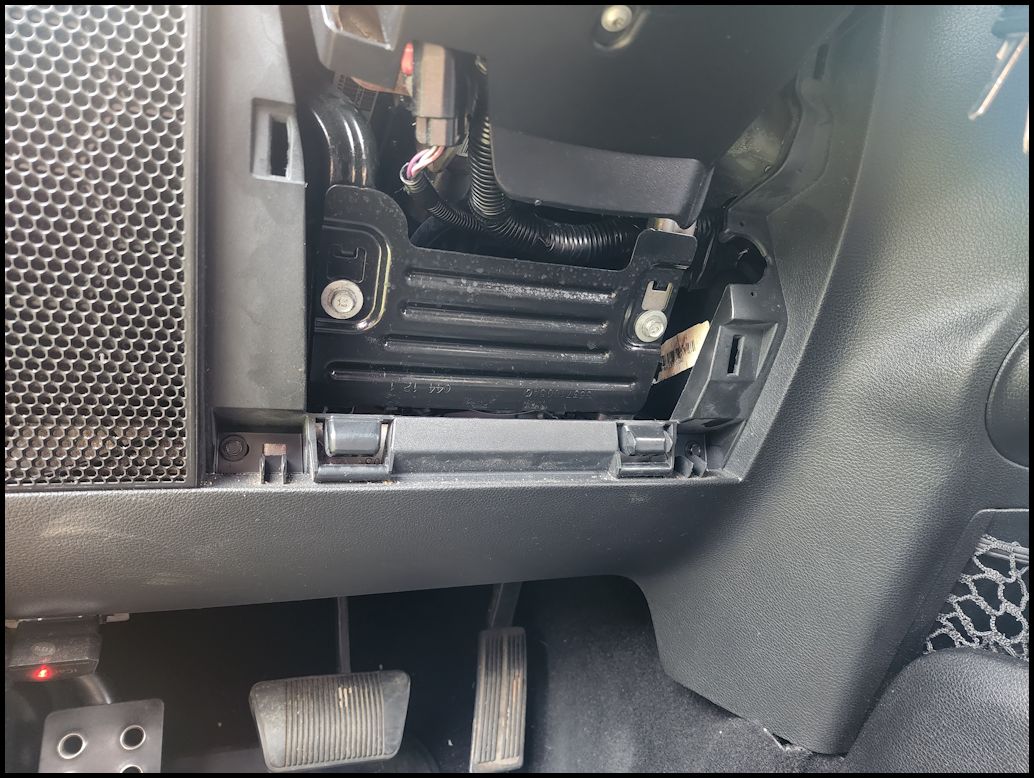
| Remove the cover from underneath the steering column. The cover pulls out from the top and swings down like the glovebox. Remove the panel from behind the cover with a 10mm socket. The cover has two clips at the top, so it lifts up and then out. |
 |
 |
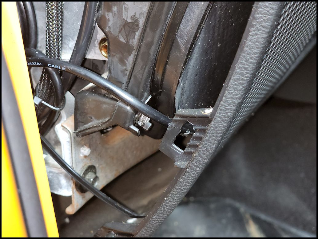
| Bring the antenna cable out through the side of the dash panel. If you ran it through the clutch cover, just feed it back through the large hole in the frame of the dash. I zip tied it to some cables that I had previously run for my sPod and air gauge. |
 |
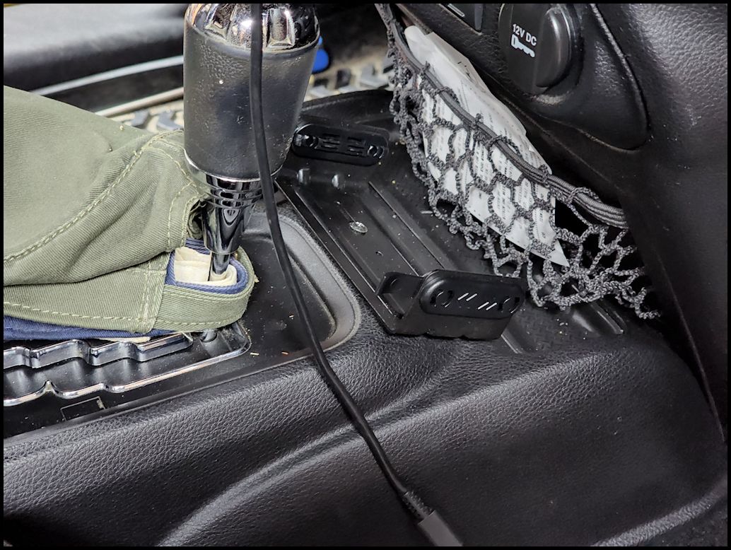
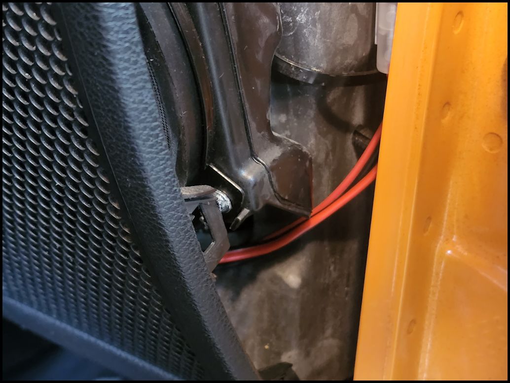
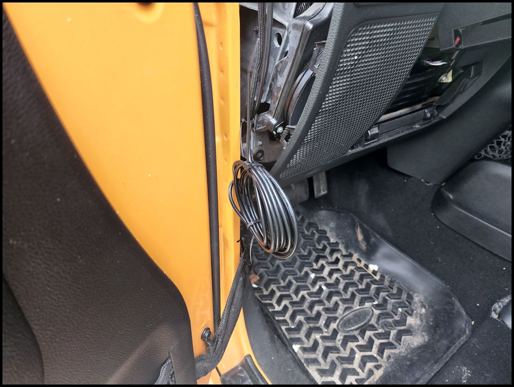
| I routed the antenna cable underneath the speaker and then across the lower dash bar underneath the panel under the steering column. Then I pulled enough wiring to go behind the center console and out just behind the GMRS head unit. Leave enough slack to be able to remove the head unit to gain access to the antenna cable. |
 |
 |
 |
| I coiled up the wire in a loop and tucked it back behind the side of the dash. I've see enough tests to prove to me that it really doesn't matter what you do with the extra length of cable. My SWR meter didn't show any difference between coiled, loose, figure eight, or crunched into a ball on the floor board. I know someone will have a fit about this. |
 |
 |
| Reinstall the side trim panel, lower metal plate and lower panel under the steering column. You will need a 10mm socket. |
 |
|
|
| |
| Hooking up the head unit: |
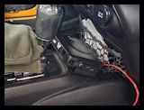
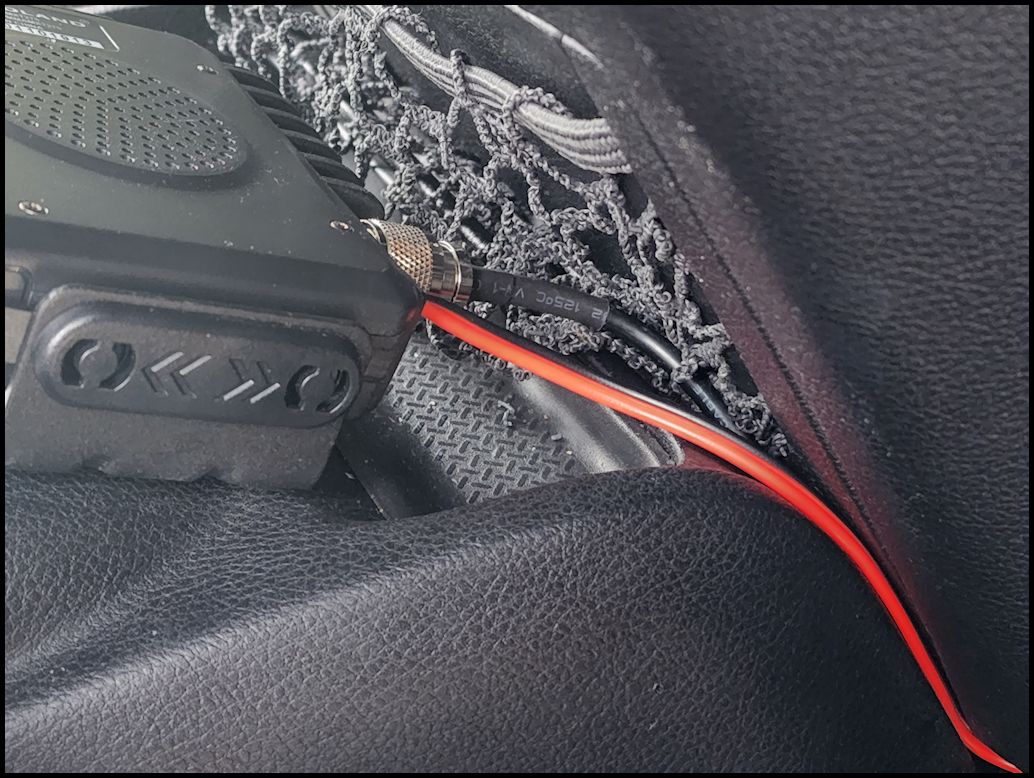
| Connect the antenna lead to the back of the head unit and connect the power lead. |
 |
 |
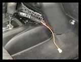
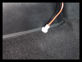
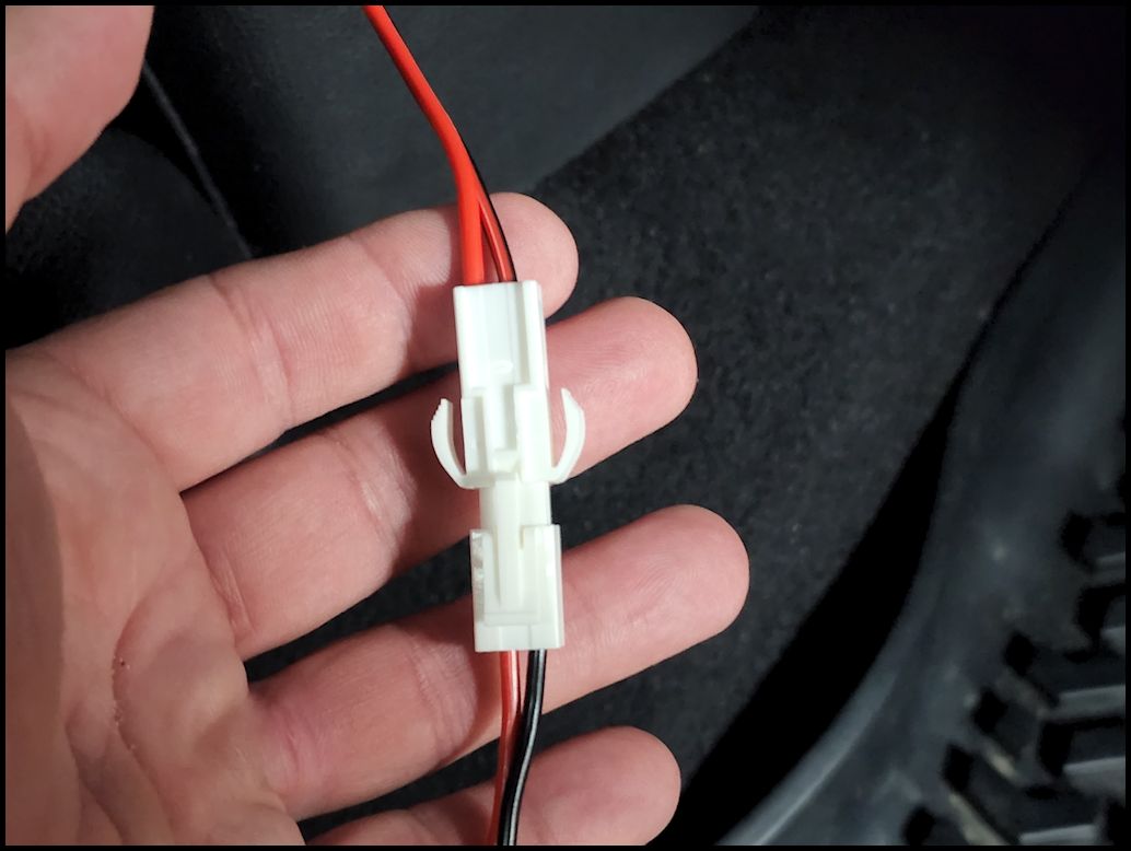
| Connect the power connectors. The ends have a specific pattern to the connector, so it only goes together one way. Make sure the connection is completely seated and the clip engaged. |
 |
 |
 |
| Install the head unit into the bracket. |
 |
 |
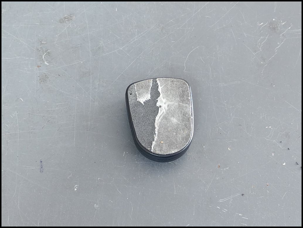
| Mount the mic holder in the location of your choice. I do not recommend relying on just the tape to hold it in place. Mine failed going down a bumpy trail and smacked my passenger in the knee. So I unscrewed the back and screwed it into place. |
 |
 |
| Plug the mic in and hang it from the holder |
 |
 |
 |
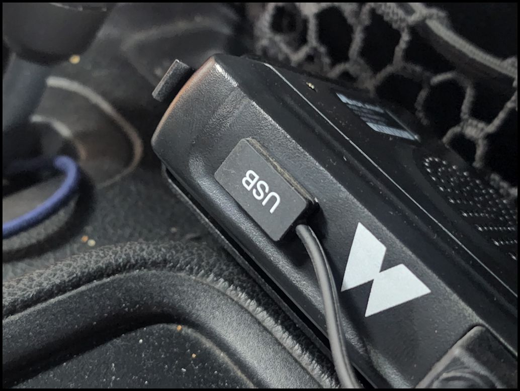
| Install the USB cover, unless you are using the USB port to charge accessories. |
 |
 |
| |
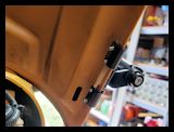
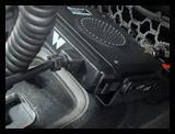
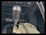
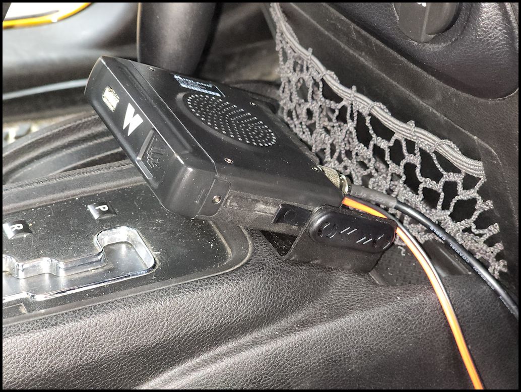
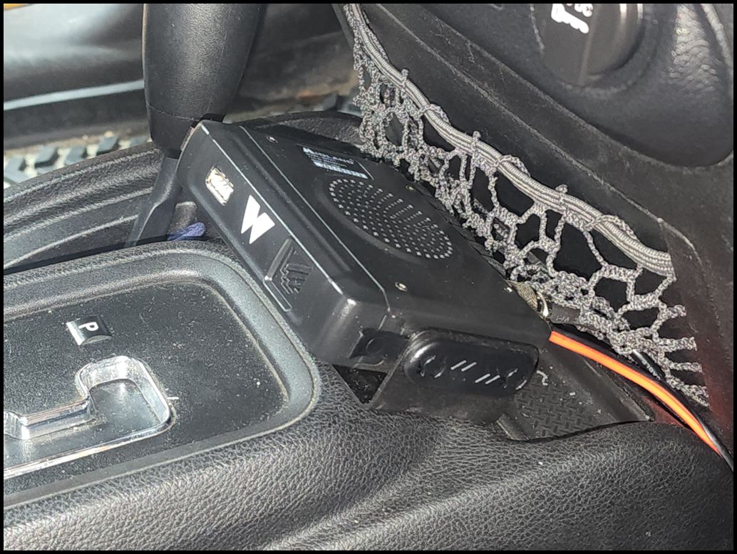
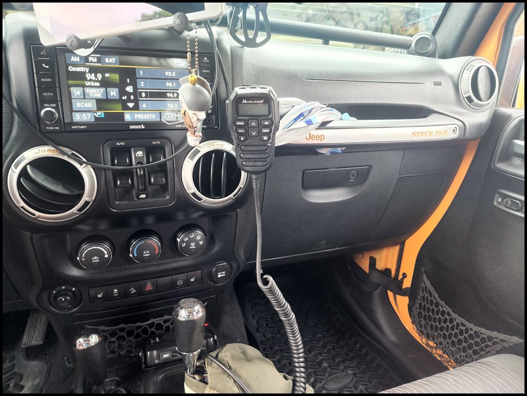
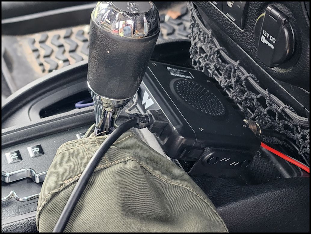
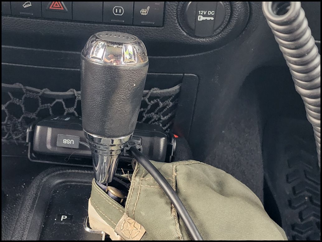
| Installed Pictures: |
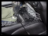
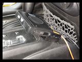
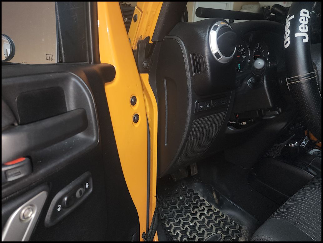
| The head unit sits out of the way in an area of the center console that I have never really used for anything. It doesn't interfer with the transmission shifter and the cable sits nicely over to the side. |
 |
 |
 |
| |
| Remote mic connection: |
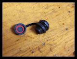
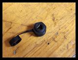
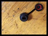
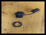
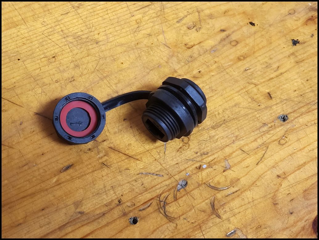
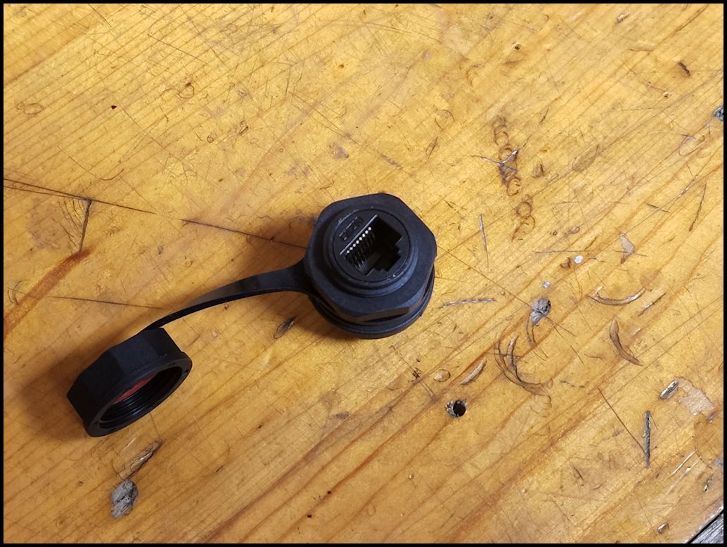
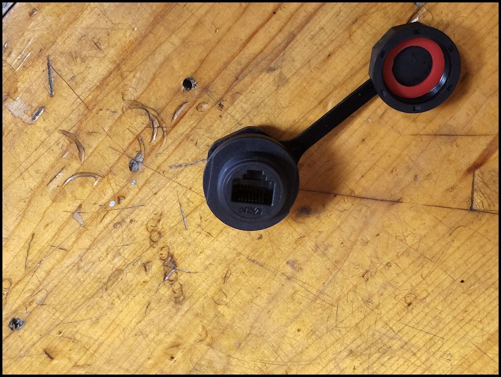
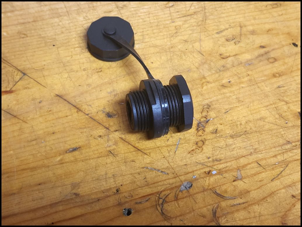
| With the head unit mounted on the molle panel in the overhead above the center console I didn't want to have the mic plugged in and have the cord hanging down from that location. I've been smacked in the head to many times having things hanging down in that area on previous Jeeps. I decided to run a remote cable to a connection on the dash. This way the Mic cable stays out of the way. I purchased a RJ45 bulkhead connector from Amazon that came with a weather proof cap installed for when I don't have the Mic plugged in. |
 |
 |
 |
 |
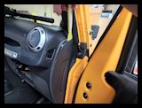
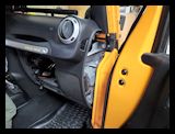
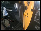
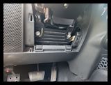
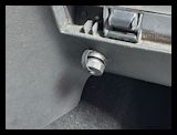
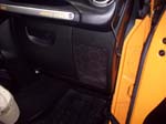
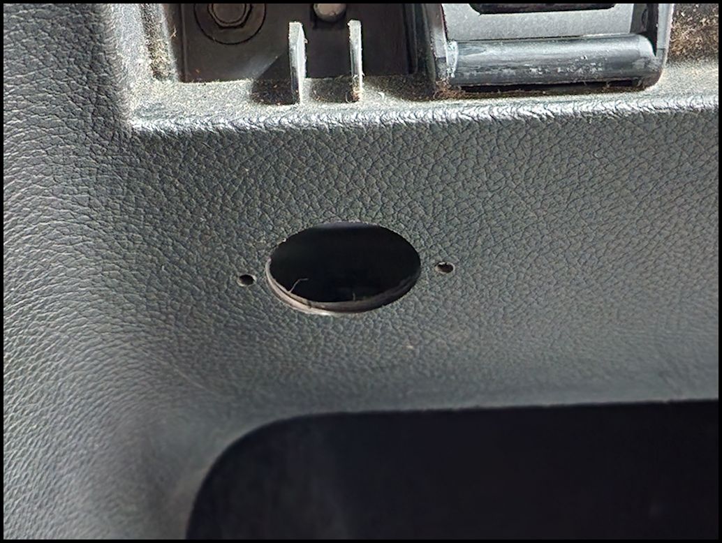
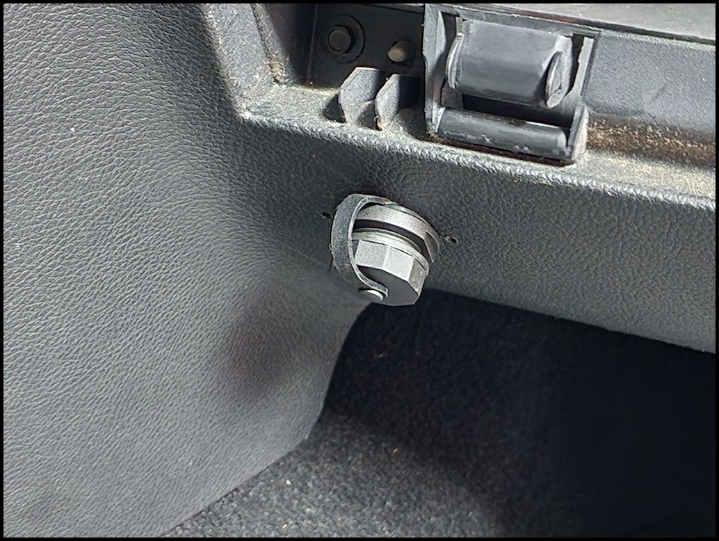
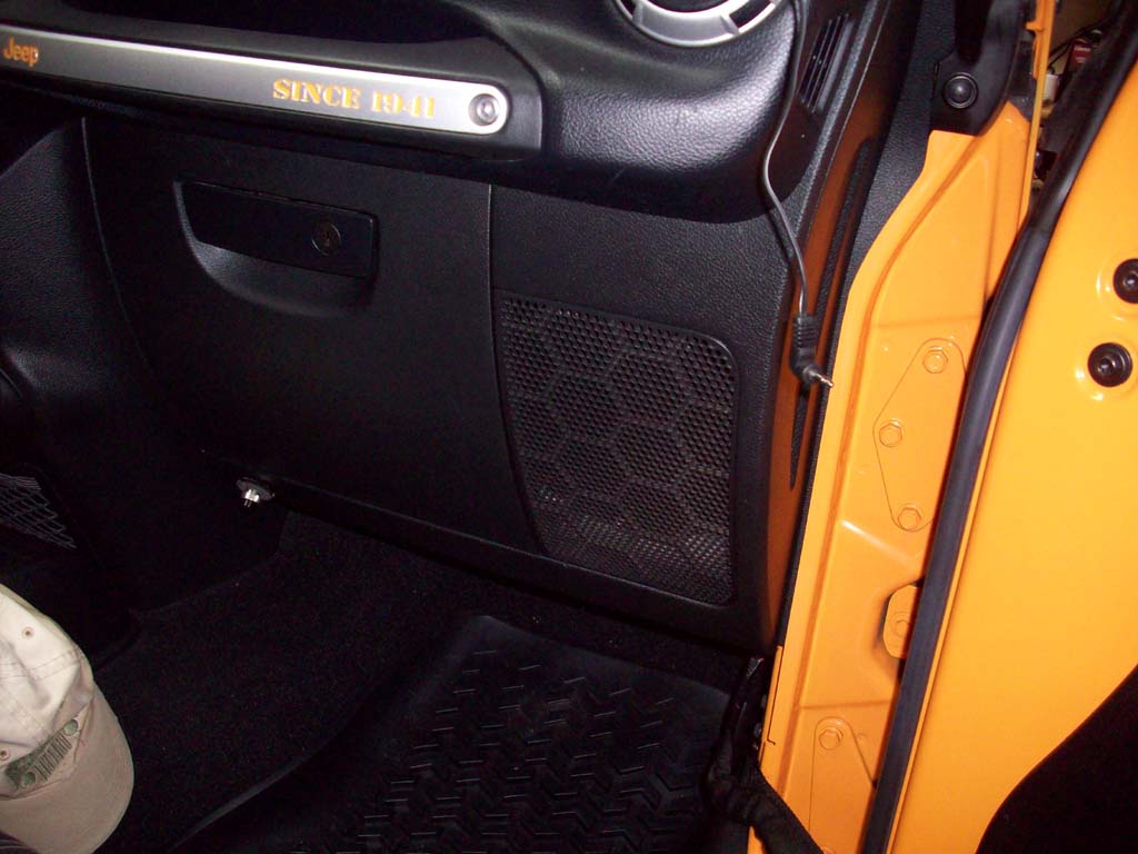
| Remove the glove box. I used the existing hole in the dash panel under the glove box that I had for my Cobra CB mic connector. The hole was a little oversized for the RJ45 bulkhead mount. If the hole didn't exist in this area I would have drilled a 13/16" hole for the fitting about half way down the bottom lip of the dash. |
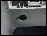 |
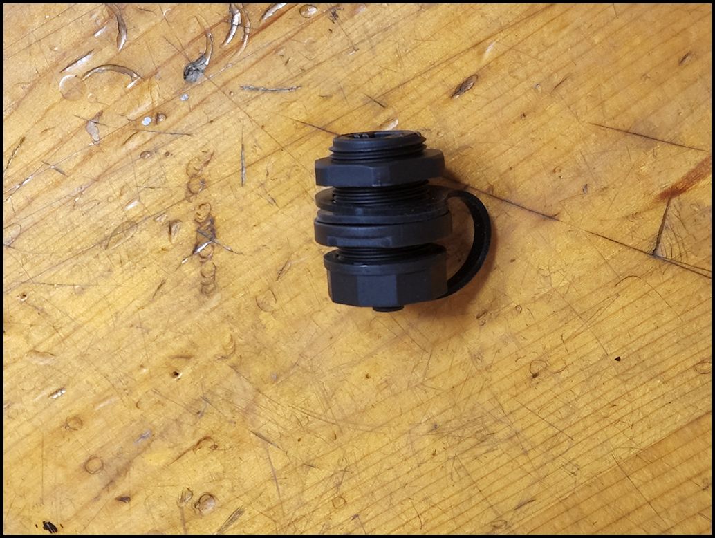
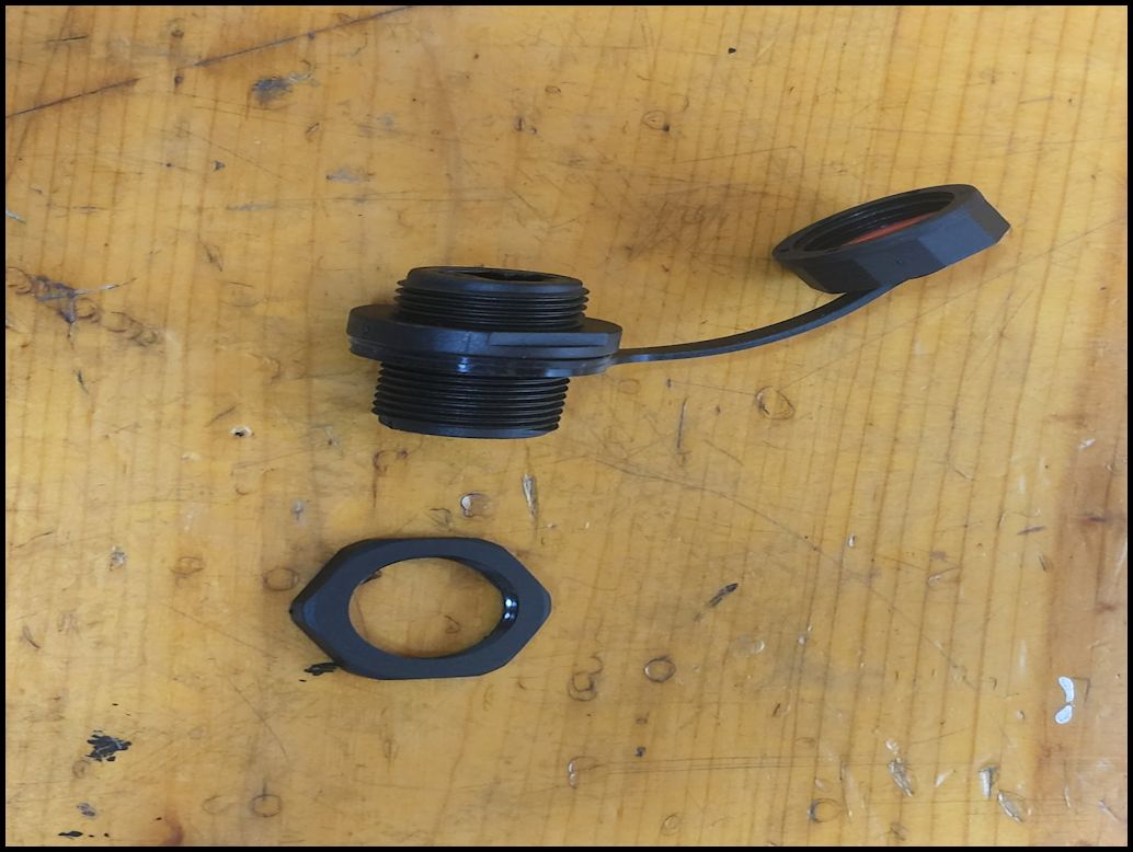
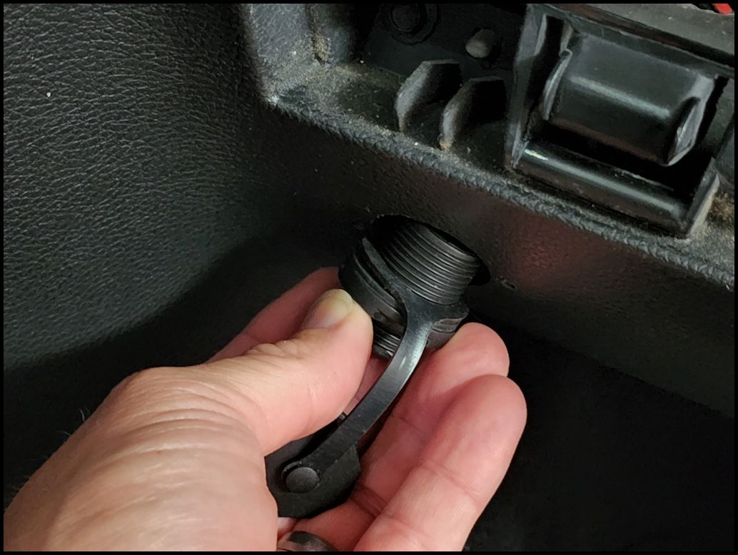
| Unscrew the nut from the back side of the bulkhead connector. Insert the connector through the hole and screw the nut back on from the back side. This area has lots of sharp edges so be carefull when you slide your hand down inside the dash. |
 |
 |
 |
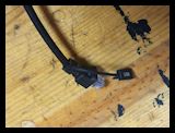
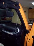
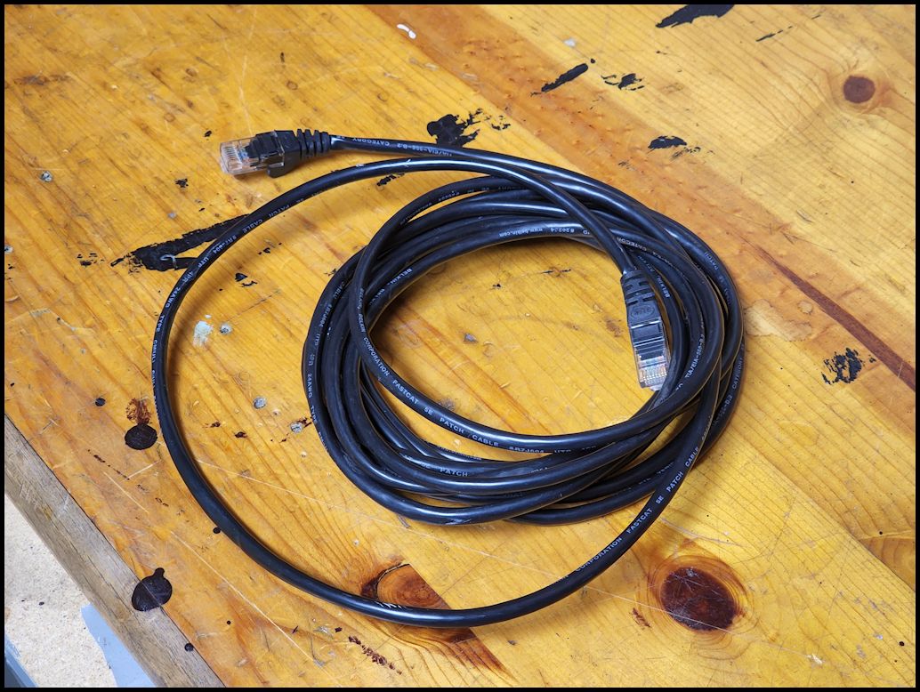
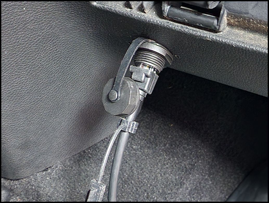
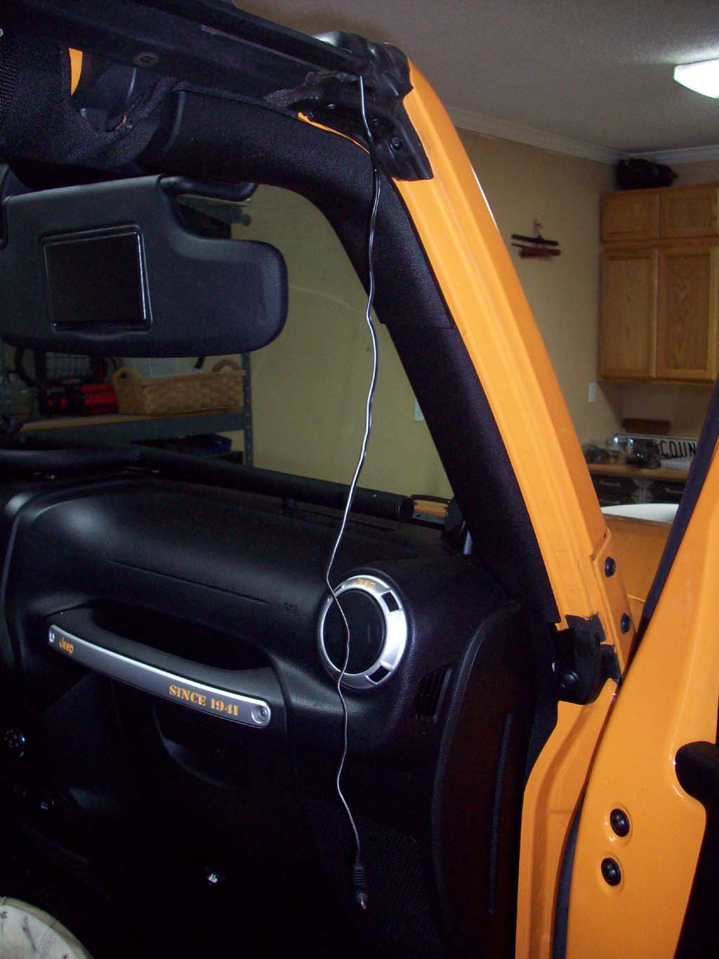
| Run a standard ethernet cable from the location of the head unit to the back of the bulkhead connector. I followed the speaker wire across the bottom of the dash, up the side of the windshield and then along the roll bar to the head unit. |
 |
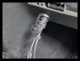
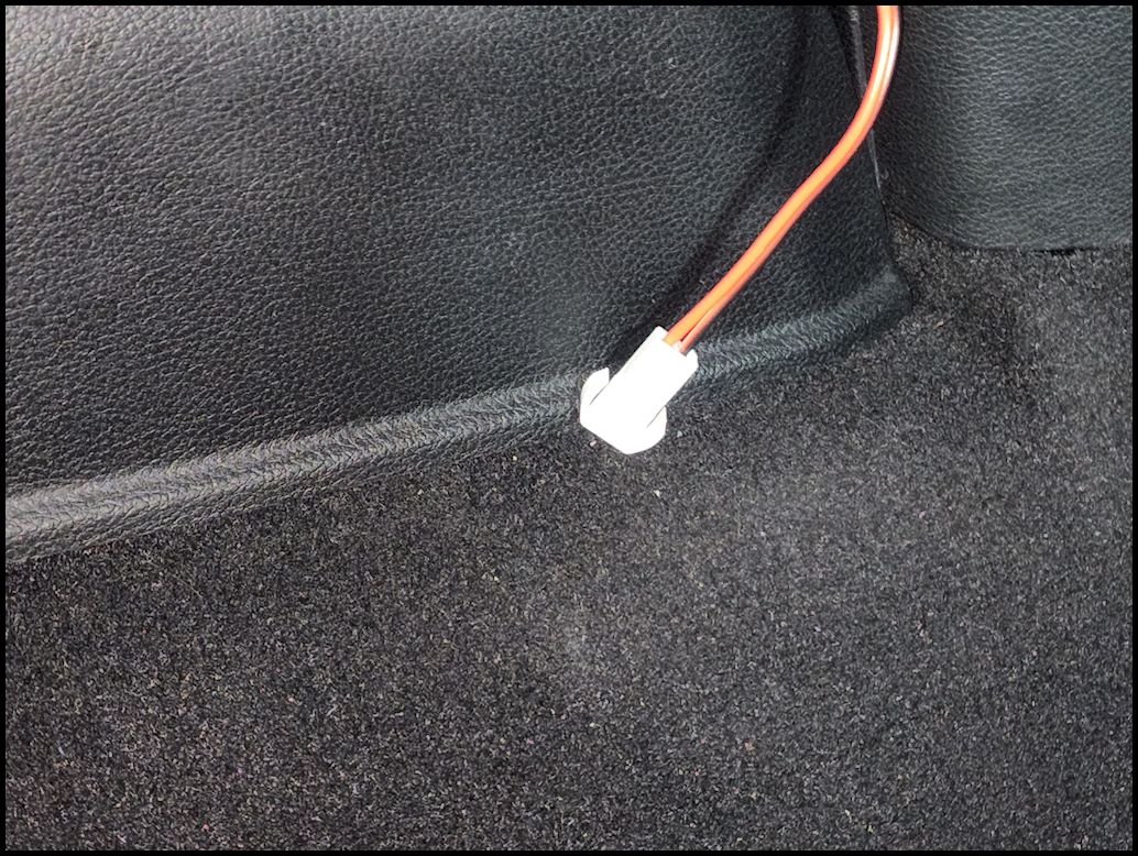
ethernet plugged in behind dash |
ethernet plugged into head unit |
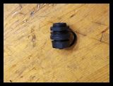
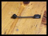
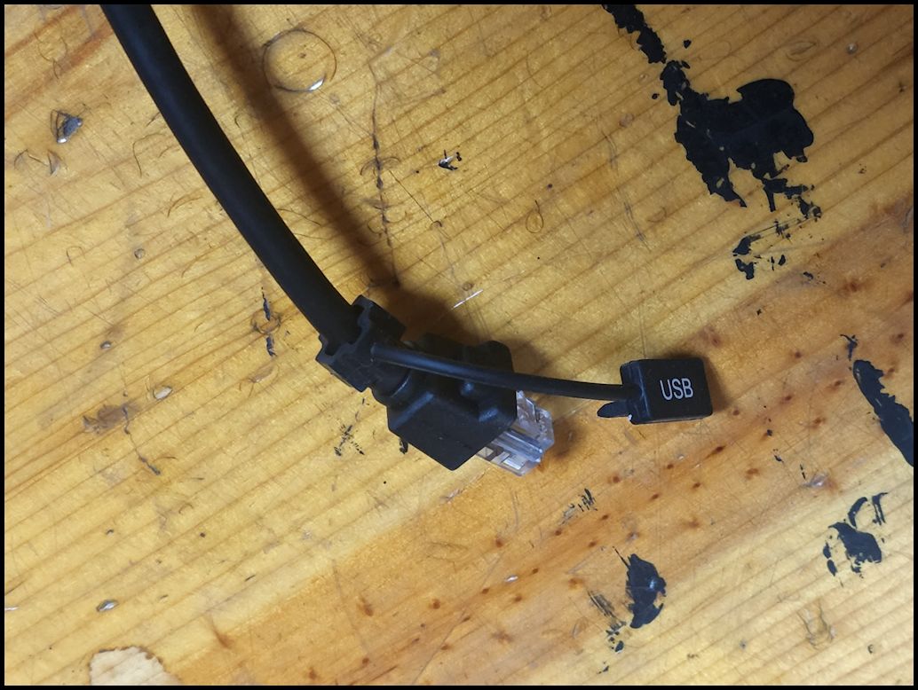
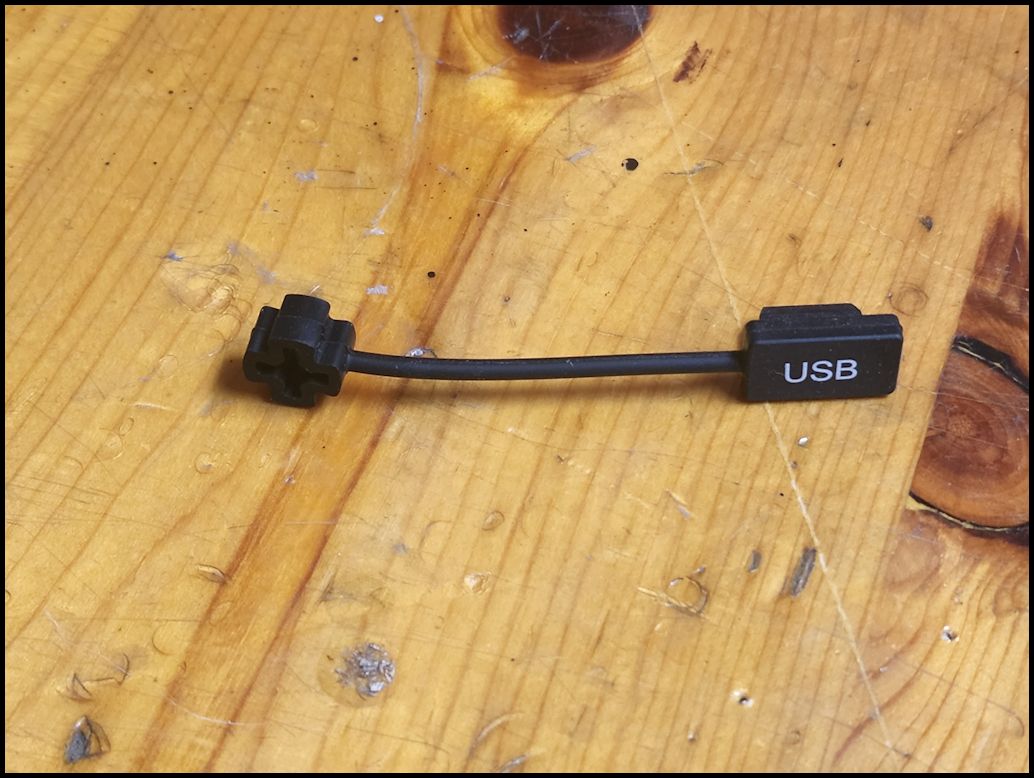
| Screw the protective dust cap over the end of the bulkhead fitting when not in use. I relocated the USB cover from the end of the mic cable to the other end of the ethernet cable. |
 |
 |
| Relocating the USB cover. Carefully stretch the end of the USB cover lanyard over the end of the mic cable. Repeat the procedure to install it on the remote cable. |
 |
 |
 |
| |
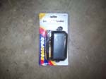
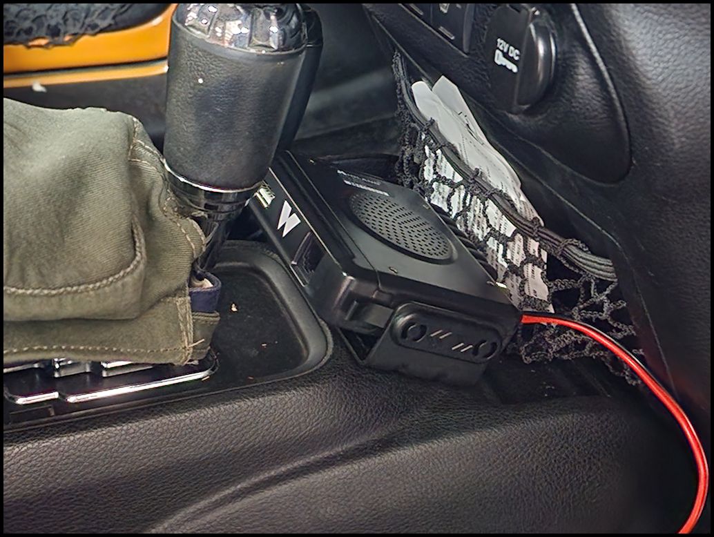
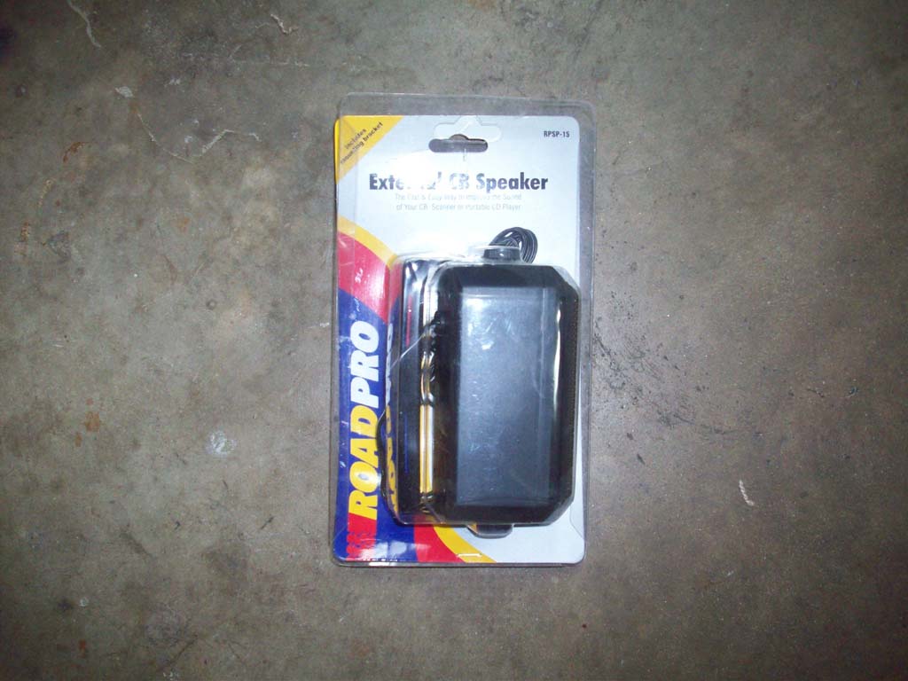
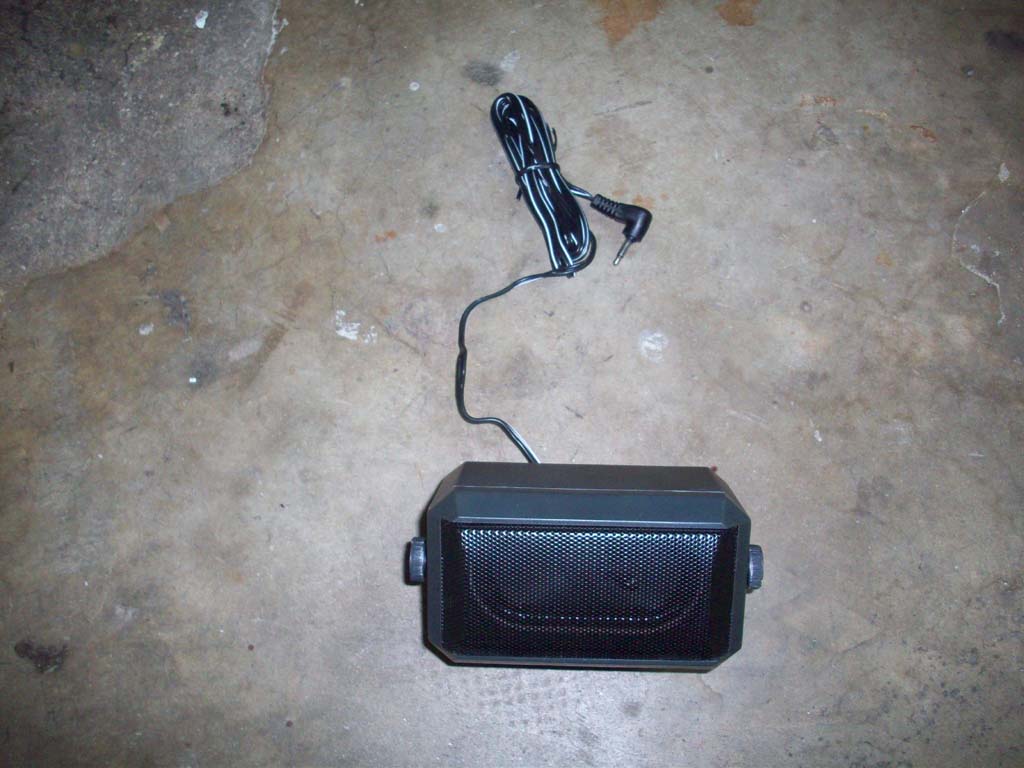
| Remote Speaker: |
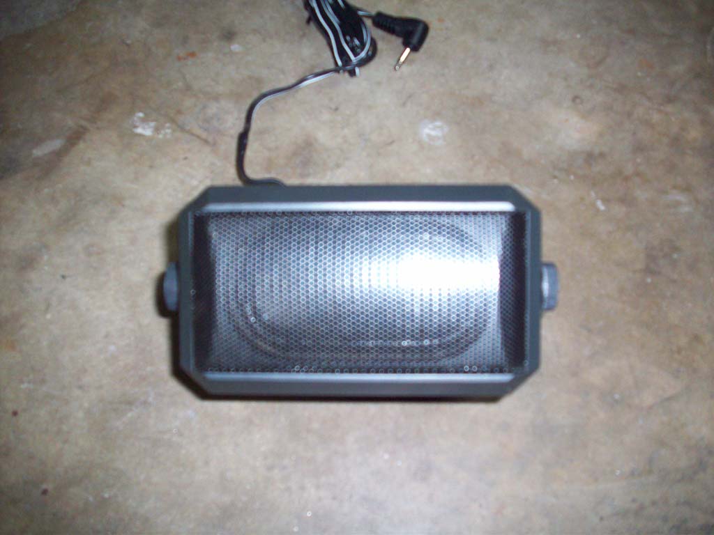
| While the speaker on the MXT275 is adequate on the trail, going down the road with the top off is another story. I reused the speaker that I had mounted for the CB. If I didn't have a speaker already I would have picked up the Midland Speaker and mounted it in the same location. |
 |
 |
 |
 |
 |
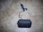
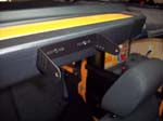
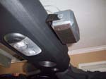
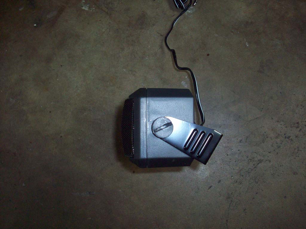
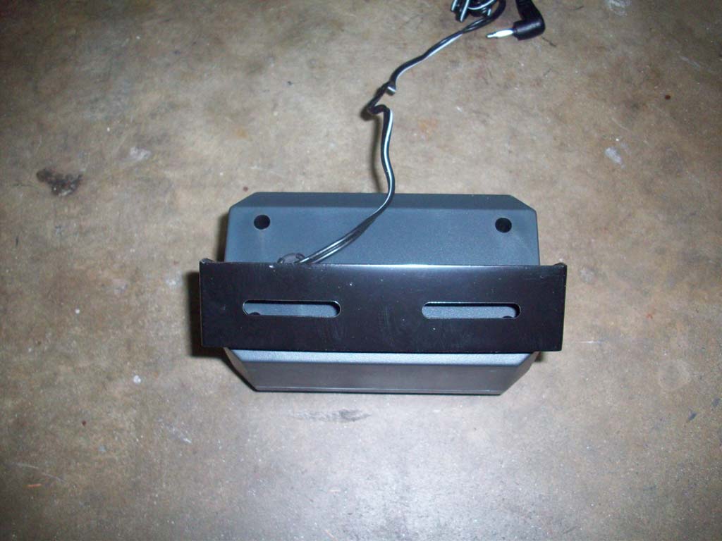
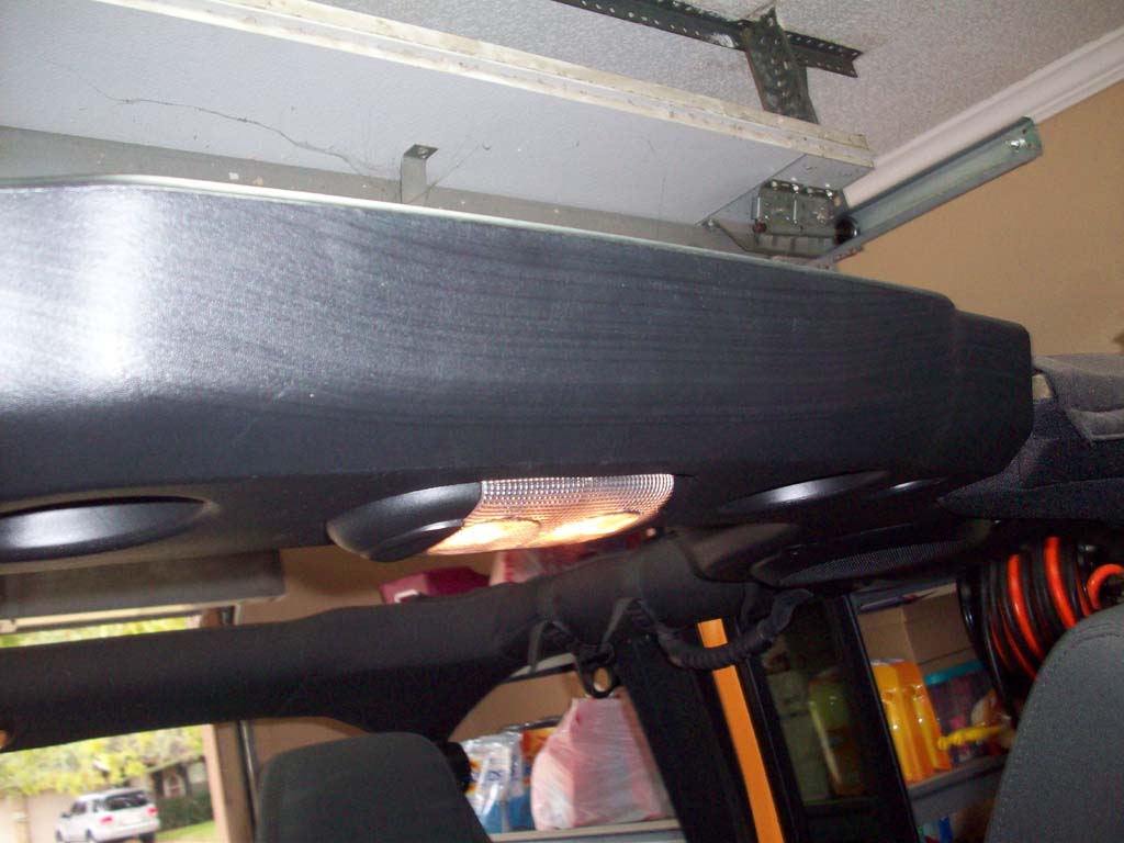
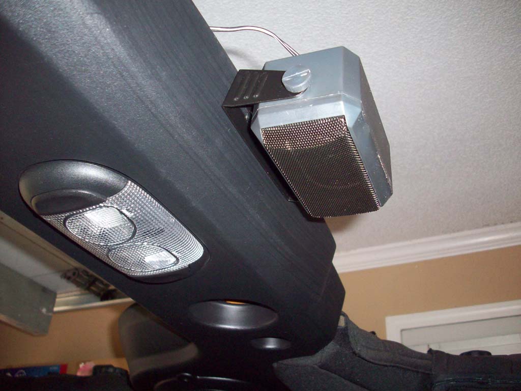
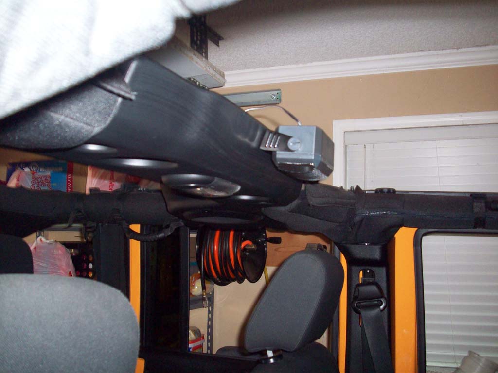
| 1. Finding a good place to put this speaker was a little difficult due to it's size, but the center speaker bar is plastic and high enough that it works fine. |
 |
 |
 |
 |
| 2. Remove the bracket from the speaker and screw it into the sound bar. The bar is plastic so a #2 phillips screw driver drove the screws right in. |
 |
 |
 |
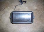
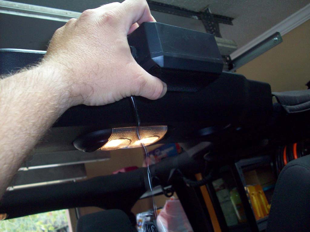
| 3. Reinstall the speaker in the bracket. |
 |
 |
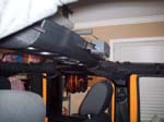 |
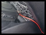
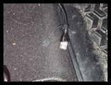
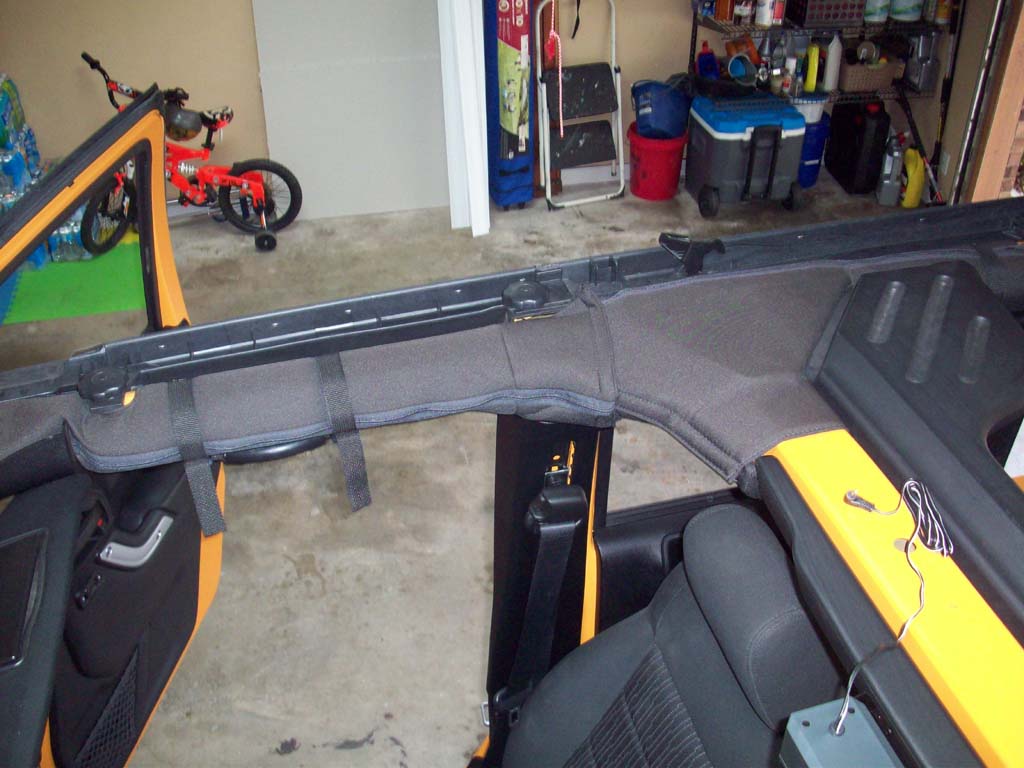
| 4. Run the speaker wire along the top of the center bar and underneath the passenger side bar covering. As you can see I couldn't quite make it to the control box under the dash. |
 |
 |
 |
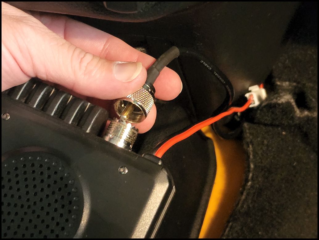
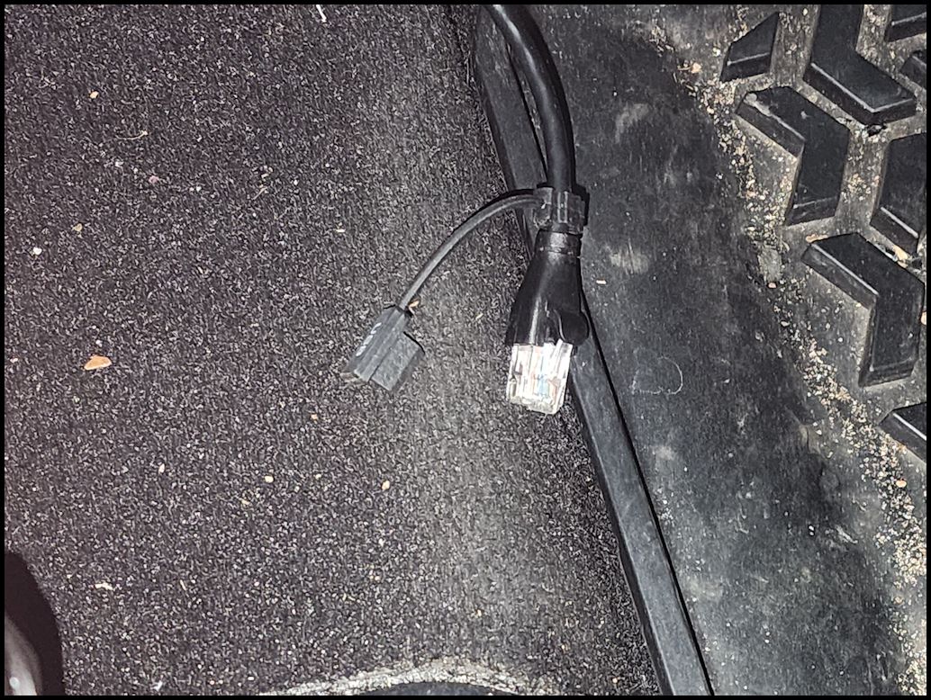
| 5. I spliced in some additional length of wire so that the speaker wire will reach the location of the head unit. I just used some small solder connectors and heat shrink tubing that I had in the drawer. |
 |
| 6. Run it along the electrical wiring that we did earlier under the dash and knee bar. Plug the connector into the head unit speaker jack. |
Pic speaker connection |
| |


