Front
Suspension:
|
Jack
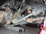
up the vehicle and place jack stands behind the front Lower Control
Arm Frame Brackets. You will need to pick this up fairly high.
I maxed out my 19" throw floor jack and put the 6-ton jack
stands up as high as I could get them. Be careful when you
set the Jeep back down. If you have a winch on the front or
a heavy bumper be ready for the rear of the Jeep to shift.
I gained about 4 inches in the back, not enough to affect working
on the front, but it did raise and eyebrow when it did it.
Now pull the tires off, I do hope that you already loosened the
lug nuts since we started on the front. |
|
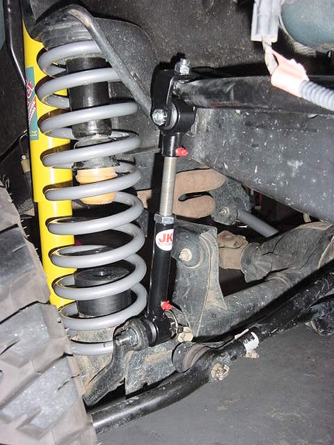
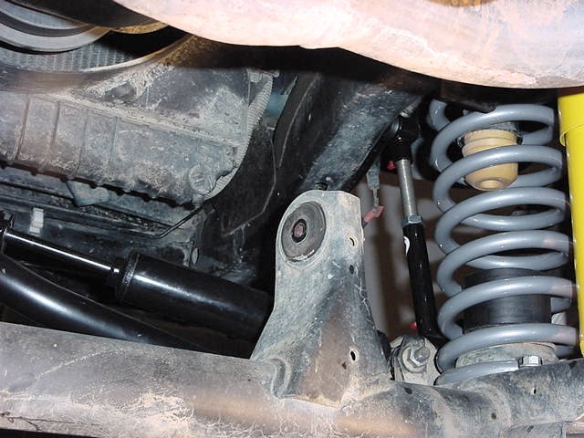
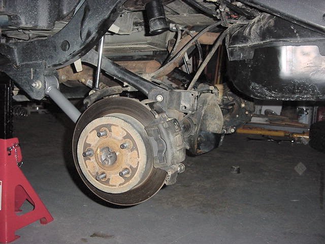
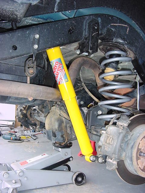
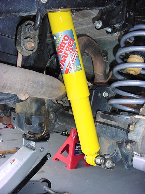
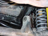
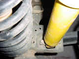
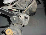
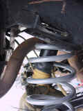
Place
the Floor jack back under the axle to hold the axle. The front
shocks are what limits your droop, so the axle will fall away once
you take the shock off, don't worry it doesn't go far, but can make
getting the shock off a pain. The front shocks. are held in
by a 15 mm nut on the shock tower at the top, and (2) 13mm nuts
and bolts at the bottom. With this being a new Jeep I was
able to get the Nut off of the top without any problems. I
placed a ratcheting box end wrench (5/8" worked, but was loose)
over the nut, and held the top of the shock tower with an adjustable
wrench. Then I removed the lower nuts and bolts. You
will need the extension on the socket to be able to reach the nuts
or bolts. |
|
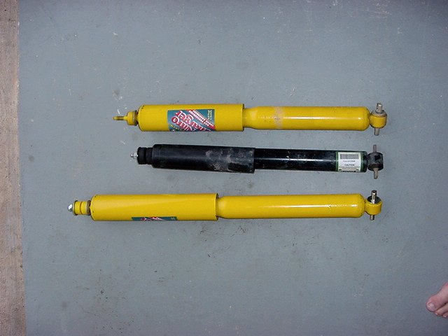
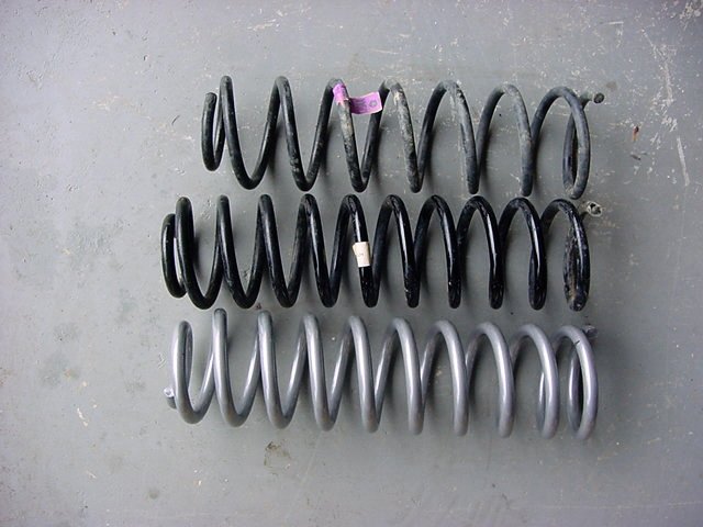
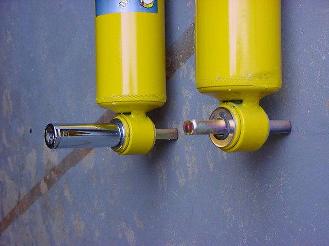
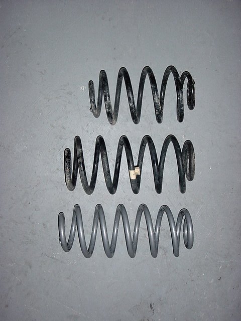
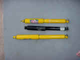
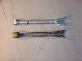
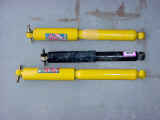
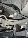
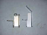
As
you can see there is a slight difference between the shocks. The
Standard OME is on top with the LT's on the bottom. |
 |
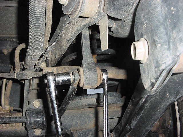
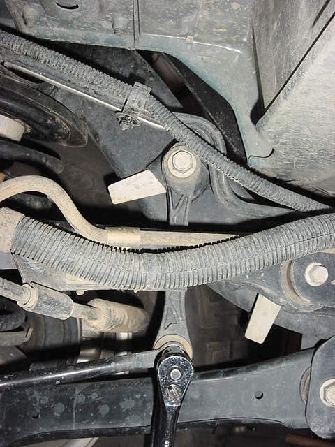
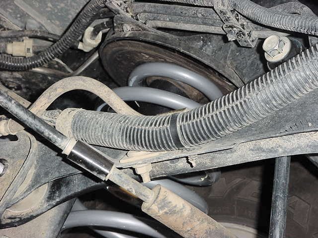
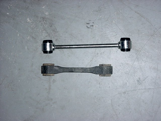
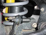
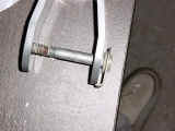
You
will need to disconnect and/or remove the front anti-sway bar linkage.
I have JKS Quicker Disconnects already
installed, so I just pulled the pins and off they came. |
 |
 |
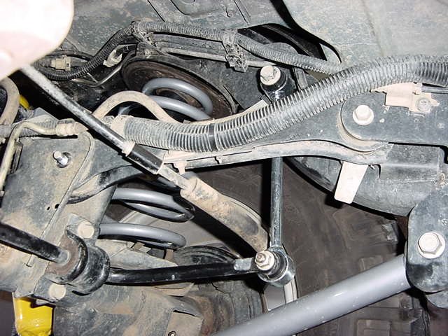
For
those of you that don't have these you will need a T-55 Torx and
a 18mm Combo wrench to remove the bottom bolt from the sway bar
link. We will remove the rest later. |
|
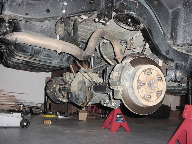
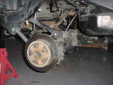
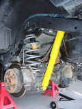
Now
that we have everything removed we need to get the spring out.
Let the axle down all the way and place the floor jack under the
opposite side brake disk. Make certain you are only lifting
the disk, not any other parts. Now jack up the disk and compress
the spring on this side. Watch so that you don't take the
frame off of the jack stand. If you do then let the jack out
until you are resting on the jack stand again. Now the spring
will be loose on the other side, so have a buddy (beer belly friends
work the best) put pressure on that disk and now pull the spring
out. Yes, you could use spring compressors to do this, but
after having one break a finger for me I don't like to use them. |
|
Repeat
for the opposite side. |
|
| |
|
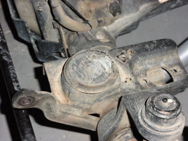
I
started by loosening the Upper control arm bolts. This will allow
the axle to rotate and move around a little. If you have cam bolts
on the front axle they say you should mark them and put them back
in the same location, but since the RE arms are longer than stock
and you will be needing an alignment anyway's, I would just center
them straight up. I don't have cam bolts on my axle, so I didn't
have to worry about resetting the bolts. I then removed the nuts
from the Lower control arm bolts. You will need a 21mm socket
to get these off. I also used a 21mm or 7/8" wrench to
hold the bolts. I removed and replaced 1 arm at a time.
|
|
I installed the zerk fittings in all of the arms since I already
had them out. These are a pipe thread fitting and require
a 3/8" wrench. Make certain that you thread these down
straight, otherwise they will strip out your hole and then you have
a real headache trying to clean it up.
|
|
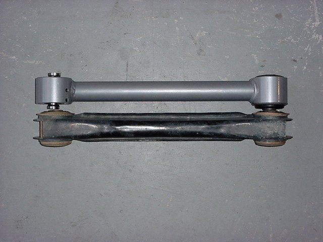
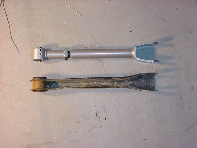
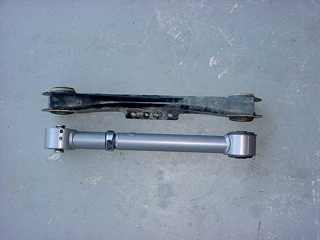
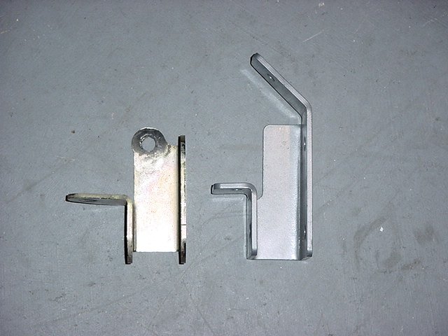
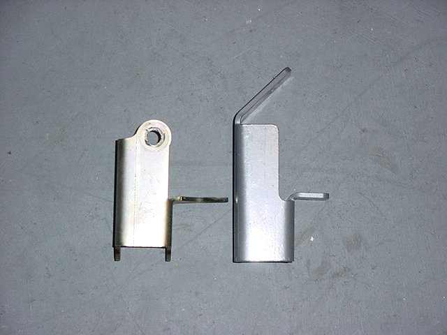
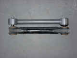
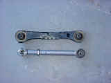
As you can see the RE arms are
just a little beefer than the stamped steel of the factory arms.
You will also notice the offset on the arm. This allows for greater
droop and flex at the axle.
|
 |
 |
I then
removed one arm. I slid the new arm up into the frame pocket
and bolted it into the axle bracket. Make certain
that the Johnny Joint is on the axle end and that the tube is
on the bottom. This will allow max droop out of the axle and prevent
the arm from binding on the spring pad for the axle. I gave the
axle a slight push with my foot and was able to slide the frame
bolt in. Now on the other side I used my bottle jack to
move the axle forward so that I could line it up.
|
|
Now repeat for the
other side. I then snugged down the bolts for the arms. Do not
tighten them since the suspension is not at rest yet.
Note: I put
anti-seize on the bolt shafts since I was inserting them through
metal bushings on the Rubicon Express Arms. This is to prevent
seizing in the future due to rust. The first thing that
I noticed about these arms once I got them installed was the amount
of flex that they have.
|
 |
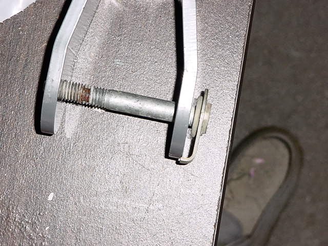
You
may note in the directions that they talk about eccentric bolts.
The eccentric bolts they are talking about are the factory bolts
that hold the lower control arms to the front axle. They are
known as cam bolts. Most 2000 and above models do not
have them anymore, just the thick washers now. |
|
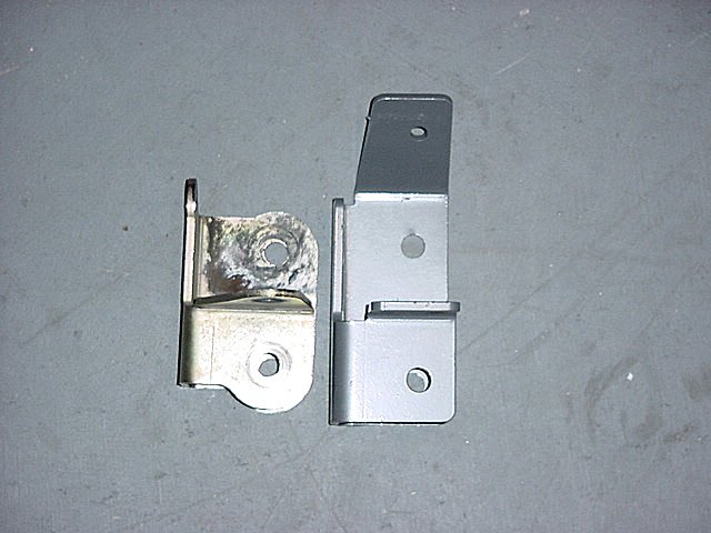
Now
for the upper control arms. As you can see these are just a little
bigger than the stock arms. I
figured the front would be easy. Okay I was wrong, it was
hard to get the tools into the tight spaces up front, especially
around the differential. |
 |
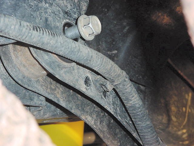
| You will need a 15mm socket for the bolts. The Frame
bracket has a nut on that tab stuck way up in there. I didn't remove
any bolts until I had all of them free. The axle bracket has a tab
on it that hooks on the arm so all you have to do is spin off the
nut. The driver side is difficult since it is right on top of the
differential. |
|
 |
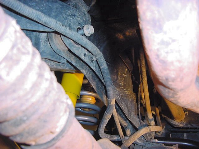
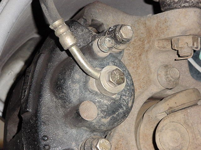
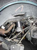
On the driver
side, you will need to remove the lines for the front locker and
differential vent. These will later get zip tied back to the
UCA. Make certain you zip ties these well, the drive shaft
is right there. |
 |
Once
you get the arms off adjust the RE UCA's to 1/4" longer.
This measurement was 13 1/4", just a little shorter than the
rears. Once you get the arms adjusted you will need to tighten
the jam nut down real tight. This takes a rather large wrench
1 1/2". |
|
|
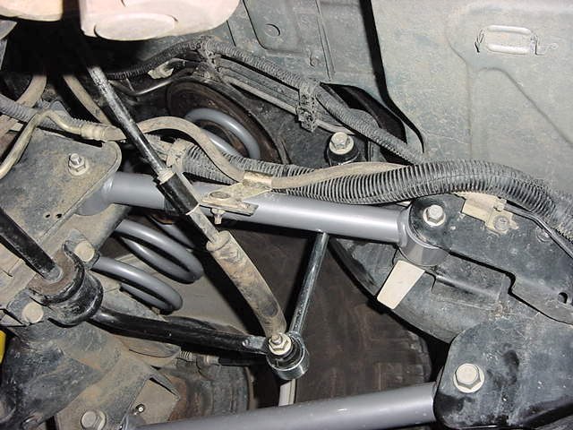
In the front you don't have the same dilemma of which
side goes where as you will see with the rears. The front's
only go in one way, Johnny joint to the frame. |
 |
I
did notice that the front arm to axle bolt didn't clip over the
edge of the RE arm like it did on the stock arm, but a quick tap
of the hammer fixed that. I choose to reuse the stock hardware (RE
didn't send bolts). There should be a new bolt with the RE arms
that goes through the axle brackets. |
 |
Now
that you have the arms in you can lower the axle down as far as
you can with it, just keep an eye on the brake lines since you haven't
replaced them yet. They will stretch a little which is okay. |
|
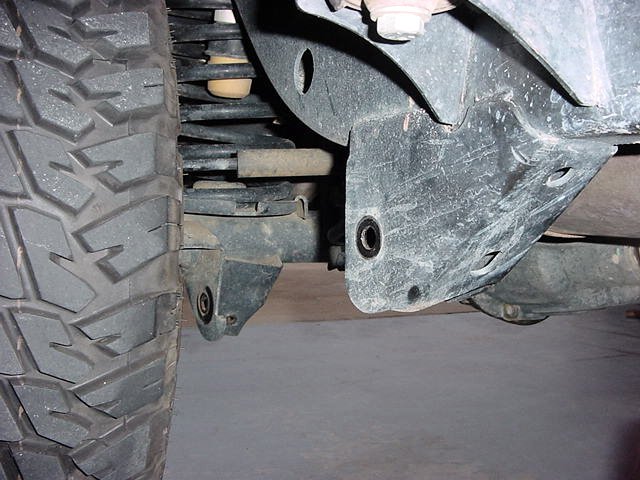
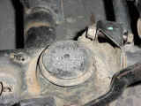
Now
to drill out the lower spring pads for the new bump stop spacers.
You will need 5/16" drill bit and a M10 x 1.50 Tap. I
know that the kit comes with self tapping bolts, but the Rubi's
have that heavy metal plate welded to the top of the spring pad,
so the Tap makes life easier. Now all you need to do is mark
the center of the spring pad. |
 |
Lay
the spacer down on top so that it is centered and take a center
punch and make a mark right down through the center of the spacer. |
 |
When
you drill out the hole you need to make certain that you drill straight
down. There is a gap between the top plate and the bottom
plate. If you don't get a straight drill, your holes will
be off and you will be unable to get a screw down through the plate.
I drilled the first one fine, but got off on the second one.
I had to cut down one of the screws so that it would fit into the
top of the spring pad. Now don't bolt on the spacers yet or
you won't be able to get the springs in. When you drill
the holes start with a small pilot hole and work your way up from
there. I drilled an 1/8" and then worked my way up, instead
of trying to drill the hole the first time. Stepping up in
drill sizes will also allow you to have a tighter clearance on the
actual hole size. Reason is that if you drill at the 1/2"
size (for example) the center point will wander in a small circle
as it drill through causing your hole to be slightly larger.
This is why they came up with the pilot point drill bits.
Get yourself some good drill bits. I used titanium and drilled
right through.
|
 |
 |
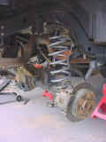
After
you get that done, it is time to put in the new spring. |
 |
| Put the floor jack under the opposite brake disk and
jack it up as far as you can, but be careful you don't lift it off
the frame. |
|
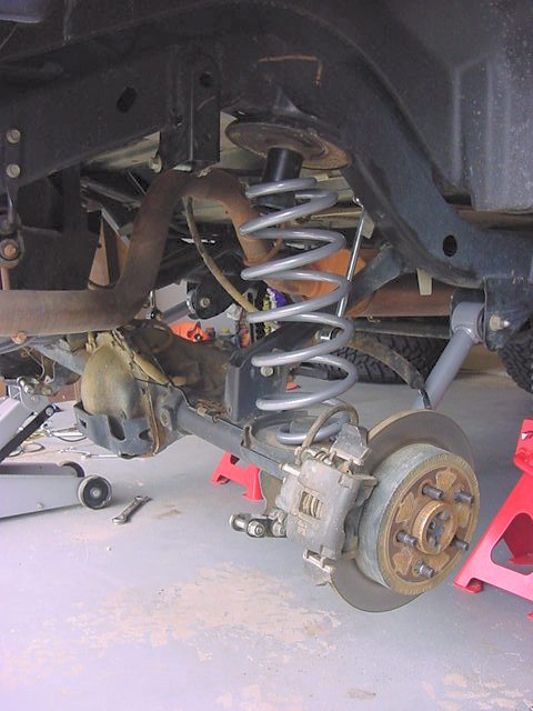
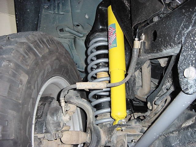
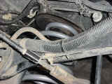
Now insert the spring up around the bump stop cup. I was able
to do this without spring compressors. The RE arms allow the
front end to really flex. Before you slide the spring over
the top of the spring perch, you will need to insert the new bump
stop into the bottom of the spring. Watch your fingers. |
|
|
Now
push the spring completely onto the spring perch. |
|
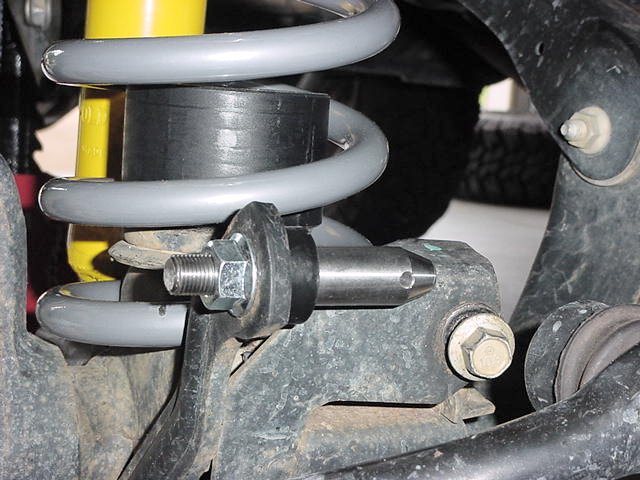
Once
you have the spring on, you will need to install the bolt in the
bump stop spacer and tighten it down. A 9/16" socket
fits the bolts. |
|
Rotate
the coil until the pigtail (end of spring) slides into the indent
in the bottom spring pad. |
|
Repeat
on the other side. |
|
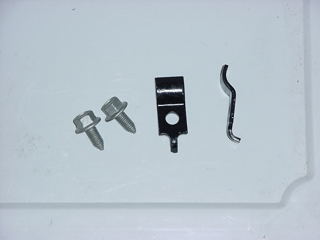
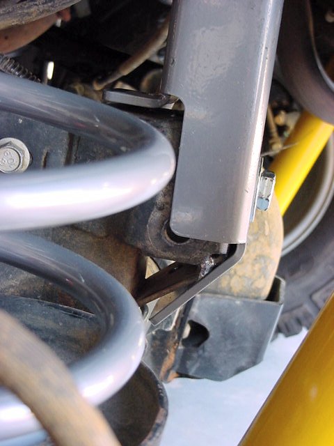
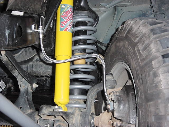
I now installed the spring clips and bolts on each
side. The front OME shocks have so much travel that they
will unseat the springs by about 4 inches, so this is good insurance
that they don't move around.
|
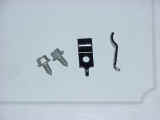 |
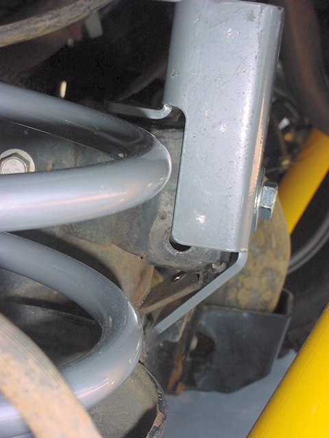
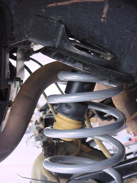
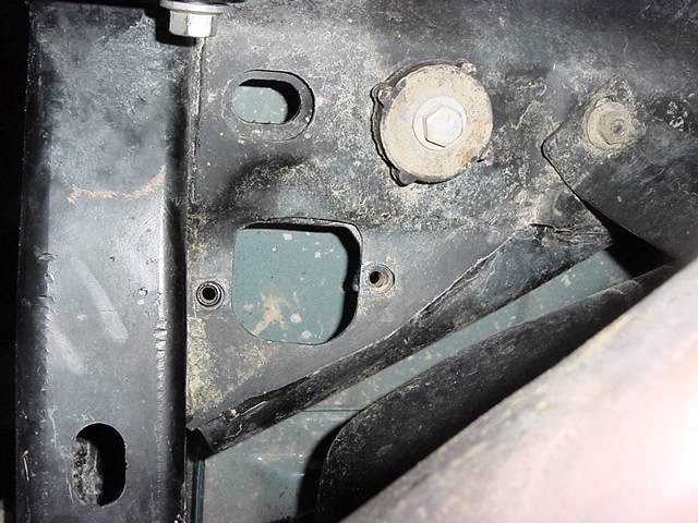
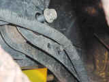
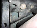
Here you
can see the two holes that the clip goes in. The rear hole (to right)
is where the little pigtail on the clip goes in, the bolt goes in
the forward hole. |
 |
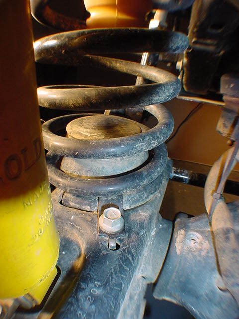
Here you
can see it installed. |
 |
Once
you are done, put the new shocks back in. Okay lets talk about
shocks real quick. |
| |
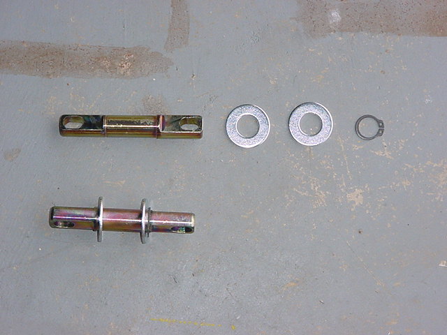
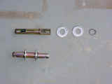
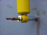
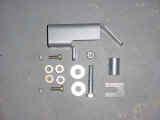
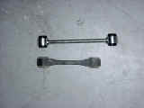
| The shocks have bar pins that need to be inserted. Pay
attention to the bar pins, and don't just dump them into a big
pile. The front bar pins are shorter than the rear and
the rears you need to make certain that you put them on the
top since both ends have eyes. A vise makes putting the
bar pins in easy, but if you don't have one take a big deep
well socket and put it on one side against the ground, and then
drive the bar pin in from the other side. Simple directions
is put washer on bar pin, drive bar pin through bushing, put
washer on bar pin, put external snap ring on bar pin.
Make certain the snap ring goes into the groove. |
| Bar
Pin Installation: |
Way
#1 (Tools required: External Snap Ring Pliers, 2 Deep well
sockets(16mm and 19mm work), Hammer)
Insert one washer onto the bar pin
so that is sits on the shoulder, wedge the end of the bar
pin in the bushing, now using a deep well socket as a support
for the bushing drive the bar pin through the bushing. It
should look like this before you hit it. Deep well on the
ground with ratchet side down, then shock bushing, then bar
pin sticking up. Drive the bar pin all the way in. Flip the
shock over and put the other washer on. Use a set of exterior
snap ring pliers, insert the prongs of the pliers into the
two holes and gently pry the snap ring open. Open it just
far enough to slide down over the bar pin, you need to kind
of get it over the round part of the bar pin, vice the flat
mounting area for the shock bolts. The snap ring will not
go into the grove on the bar pin. Now take another deep well,
that will just fit over the bar pin, give the deep well a
couple of smacks with the hammer working the snap ring down
and into the groove. |
Way
#2 (Vise, External Snap Ring Pliers)
Basically the same way as #1, but you
can use the vise to press in the bar pin, and hold the washers
in, while you install the snap rings, this way you can actually
install them right into the groove, with out having to use a
deep well and a hammer. Only problem is you lose that satisfying
thunk of the hammer. |
 |
 |
 |
| |
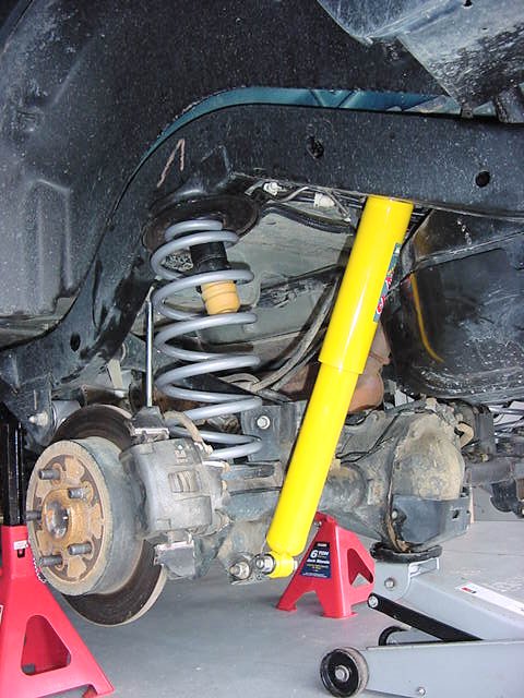
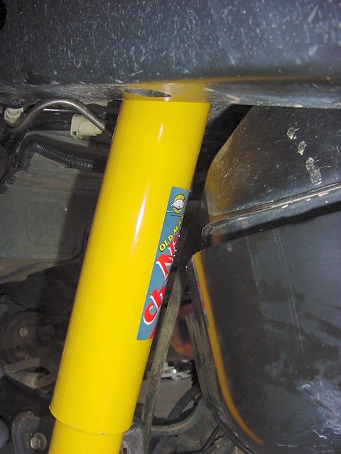
Installation
of the front shocks is the opposite of removing them. You will need
a 13mm socket, short extension, and combo wrench for the bottom
and a 17mm for the top. You may need to lift up on the axle to set
the shocks in the bottom |
|
Once
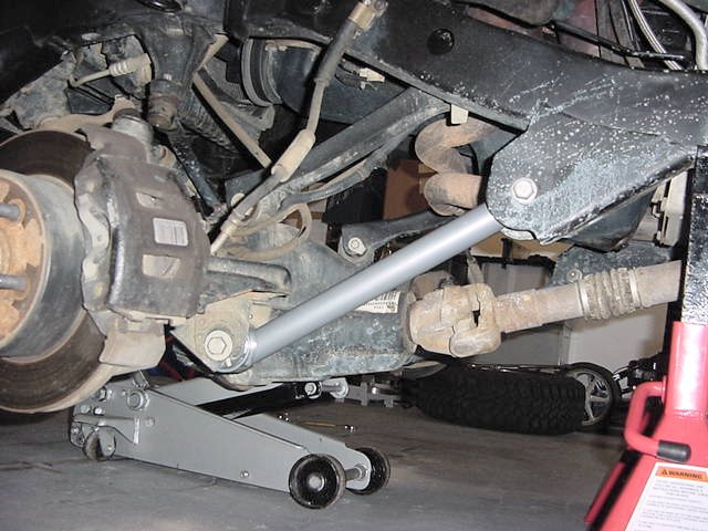
you have those installed you can move on to the front trackbar. |
|
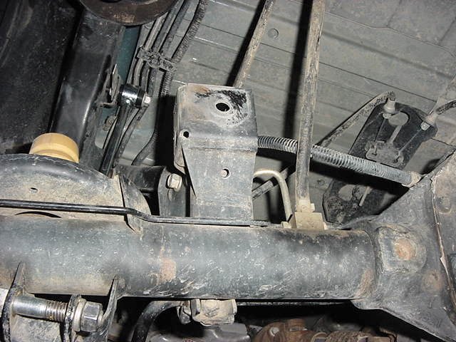
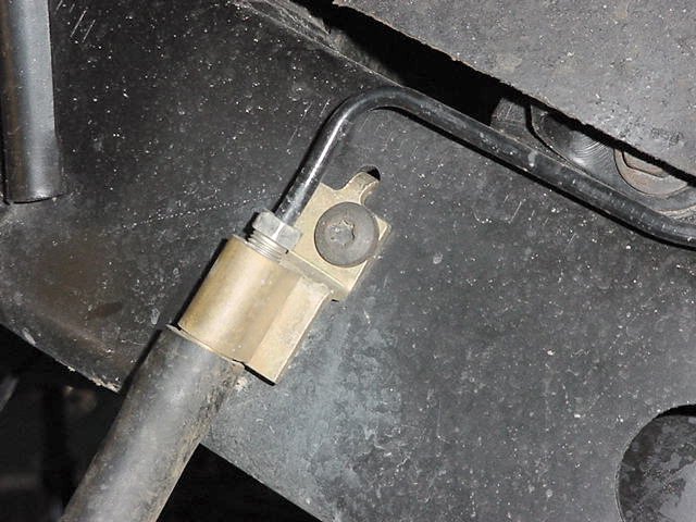
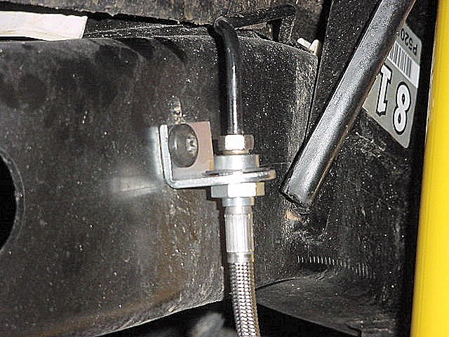
If
you don't replace the front track bar you will need to drill an
new hole. As far as the track bar drill point. If I
remember correctly the RE instructions state drill it 3/4"
over from the factory hole in the axle bracket. When I did
this on my friends 98 TJ, we just drew a line from the factory hole
(towards the ds) parallel with the axle. We marked it at 3/4"
then drilled the first hole. We did the same thing for the
inner hole that way the holes were straight. You won't have to remove
the trackbar, just remove the axle side bolt. |
|
|
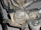
|
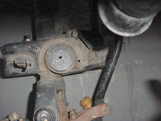
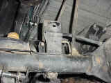
First remove the cotter pin and then the 15mm castellated nut from
the frame side mount. |
|
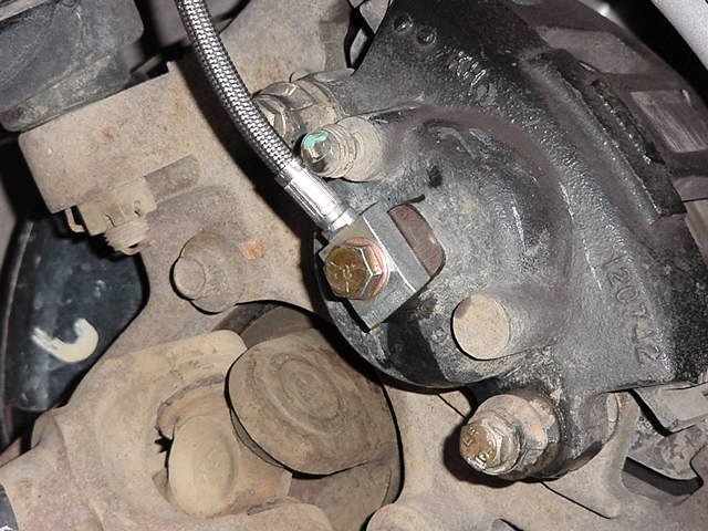
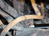
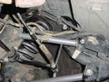
Then
take a pickle fork and drive it between the top of the track bar
and the frame bracket. Be careful that you get the tines of
the pickle fork centered around the taper bolt otherwise it is a
real pain. I found it easier with the flat side of the pickle
fork against the frame bracket. |
|
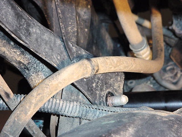
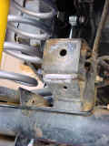
Now
use a 15mm socket to get the bolt out of the axle side mount.
There is a capture nut on the back side attached to the little tab.
Note: Be careful putting this back in, I stripped mine out, and
have waited over 4 weeks for the dealership to figure out the right
part number. |
|
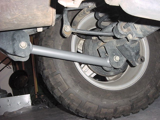
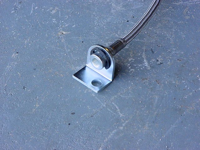
Now
just slide the bar out and put it off to the side, I now installed
the JKS bar as the link above shows. |
|
|
|
Go
ahead and put the tires back down and take it off of jack stands. |
|
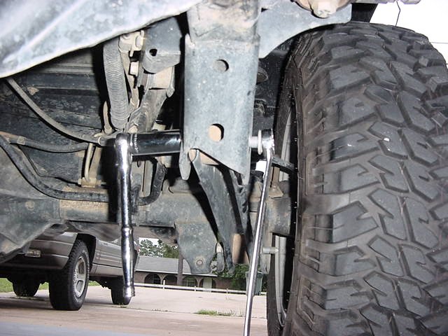
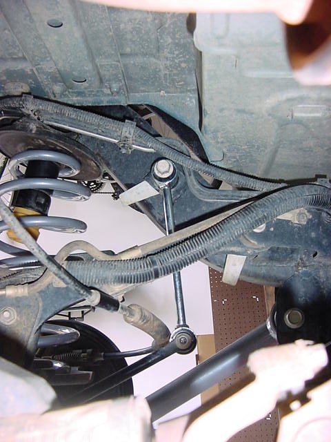
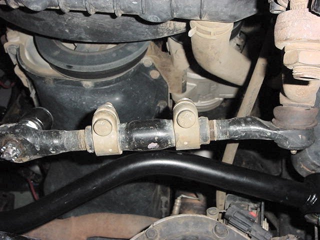
| Now reinstall the anti-sway bar end links. You
will notice that this pulls the anti-sway bar below horizontal.
The effective range of the anti-sway bar when the vehicle is on
the ground is +/- 20degrees from horizontal. The preferred
range is 20 degrees above to 5 degrees below horizontal. I
extended mine to about 10 1/2". |
|
You
will notice that the front axle is off center. Just a quick
blurb here about that since you are not quite ready to go drive
it. |
|
Centering
the front axle is easy. You don't have to bounce or anything. |
|
First
measure from the frame to the rim/ or tire as close to right above
the axle. This will eliminate the possibility of the body being
off center on it's mounts and having a slight turn in the tires.
Now once you have this measurement, you will know how far you need
to move the axle. I had initially measured my axle position and
saw that I was just slightly over to the drive side. When I installed
the new bar I offset it the same amount. |
|
Second,
once you have this measurement. Adjust the Trackbar to 1/2 the difference
in distance. My length ended up being 31 1/4".
Now all you have to do is turn the front wheels and the axle will
move underneath the frame. Once the track bar lines up with
the axle bracket, install the bolt and nut. Then just drive
it around and remeasure (after you get the rear suspension done,
yes someone asked me how to drive it around with the front end up
in the air). |
|
| Rear Suspension: |
Jack
up the rear suspension and place it on jack stands just in front
of the Rear Lower control arm frame brackets. |
|
Now
let the suspension down and remove the tires.
|
|
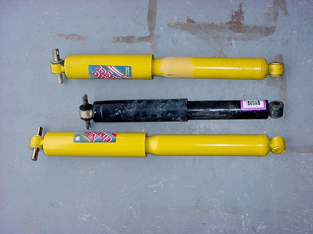
Support
the rear axle with the floor jack and remove the rear shocks.
As you can see the rears are small compared to the standard OME's
and the OME LT's (bottom). |
 |
You
will need a to remove the (2) 13mm bolts from the top (real long
extension), and the lower bolt is a 15mm and 18mm. |
|
|
Now
remove the rear track bar so that you can install the springs and
trackbar bracket.
|
|
The
axle ends uses a T-55 Torx and the frame side is a 15mm and 18mm.
|
|
You
will also need to remove the plastic cover from around the axle
end of the track bar.
|
|
I also removed the rear anti-sway bar links. A 15mm and 18mm
socket takes out the bolts. I left this disconnected because
I knew I needed to move the axle around so that I could drill for
the track bar bracket. These will limit your ability to droop
the axle far enough to get a drill in.
|
|
 |
|
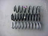
Now
to get the rear springs out, just let the axle droop all the way
down, and have a buddy step on one side, pull that spring out, and
then go do the other side. As you can see the RE spring isn't much
bigger than the OME spring in the center. The RE spring has more
wraps and a larger wire diameter. |
|
|
|
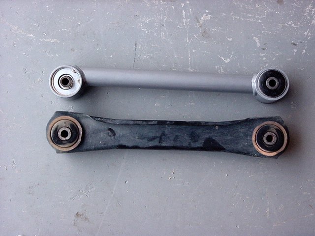
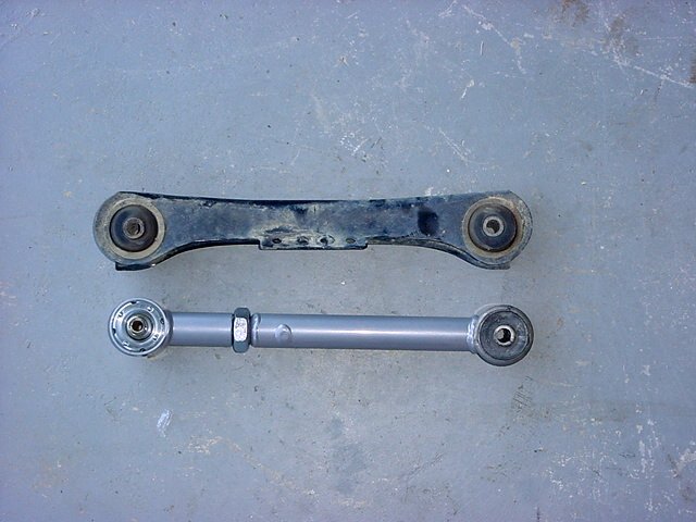
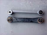
As you
can see the RE lower arms are beefier than that stock arms. Like
in the front the lower arm gets installed with the johnny joint
on the top side of the arm in the axle bracket. (Yes the arm is
upside down in the picture) |
|
|
I
started by removing the nuts from the Lower control arm bolts.
You will need a 21mm socket to get these off. I also used
a 21mm or 7/8" wrench to hold the bolts.
|
|
|
I
slid the arm up into the frame pocket and inserted the bolt into
the axle side mount. Now I gave a little push up on the body,
and the frame bolt slid right in. I did the opposite side
the same way. (This is a shot from my friends jeep that we
replaced a RE arm on.) Once I had both control arms in and all the
bolts inserted, I reinstalled the nuts.
|
 |
Adjustable Upper
Control Arms. The instructions say to adjust these to 1/4"
longer for stock drive shaft and 3/4" longer for a CV shaft.
I still had the stock shaft, so I went the 1/4" route.
I used 2 pieces of all thread to make certain that both arms were
the same size. I first installed the zerk fittings in all
of the arms. A 5/16" wrench makes short work of these.
As you can see these arms are also bigger. Unfortunately they
do not come with a bracket for the brake cables, air lines, etc,
that are attached to the stock arms.
|
 |
 |
You
will need a 13mm socket to get the emergency brake cable off of
these.
|
 |
Now
15mm socket and combo wrench for the bolts to remove the control
arms.
|
|
 |
I
then measured the stock control arm from center to center on the
eyes and adjusted the RE arms to 1/4" longer. This measurement
was 13 1/2". Once you get the arms adjusted you will
need to tighten the jam nut down real tight. This takes a
rather large wrench 1 1/2".
|
|
Now
since the RE instructions never stated which side the bushing when
on and which side the Johnny joint was installed, I figured I would
just put the bushing on the frame side. I don't know if this
is right, but I have no noise from it. I installed the bolt
in the axle mount, and left the control arm hanging. I then
removed the other side and repeated.
|
|
Once
I had both arms attached at the axle, I jacked up the pinion and
inserted the bolts into the frame brackets.
|
 |
I left the emergency brake cables loose for the moment, I will zip
tie them to the UCA's, once I had a chance to see how everything
rides.
|
|
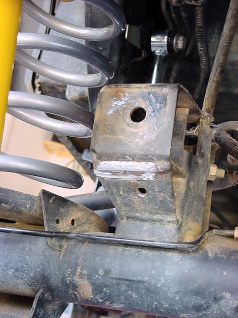
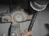
Now
to install the track bar bracket. This was a pain to put in.
You will need to drill 2 holes in the original bracket, in the holes
that the clips that were holding the plastic cover were located.
Now don't go drilling these right away. I said it before every
jeep is different, and you need to use the bracket as your guide.
Of course you will either need an angle drill, or a short electric
drill.
|
 |
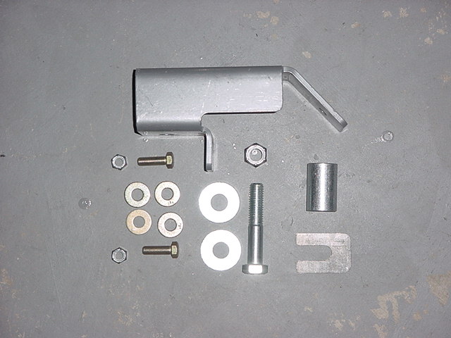
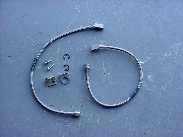
RE Parts |
OME vs RE |
|
|
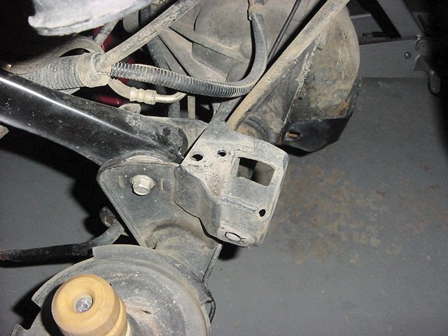
First
thing you do is bolt the bracket on in the original location utilizing
the supplied bolt (3/4" socket and wrench), spacer and nut.
Getting your fingers into the little holes to put on the washers
and nuts can be fun and entertaining for those watching you.
Now mine didn't fit.
|
 |
I took a look at the axle bracket and realized that I needed to
do a little grinding on the very sloppy weld. Once I got the
weld ground down I could put the bracket on. Okay I was able
to get the bolt and spacer into the original location of the trackbar.
|
 |
I
saw that the bottom bend in the bracket would need a little persuasion,
and that the top hole did not line up with where Rubicon Express
said you needed to drill, close, but not right on.
|
 |
I needed to drill the top hole first. So I jacked up the opposite
brake disk and was able to get a drill in. Now this time I
just went with the big drill bit 5/16" so that I could drill
the hole. I was going to hit the hole slightly off center,
so I needed the big drill bit.
|
 |
Once
you have the hole drilled you can insert the spacer under the Rubicon
Express bracket and then insert the bolt (1/2" socket and wrench)
and tighten it down. If you manage to drop the nut or washer,
it will fall into the axle bracket and takes a little bit of work
to get out. Luckily I had some hemostats that worked very
well.
|
|
Now
that I had 2 bolts in, I needed to persuade the bottom of the bracket
to lay flat against the axle bracket. After a moment of reflection
I whacked it with my 3lb black smith hammer. Gotta love a
resounding thunk. With the bracket now molded to the axle
bracket I was able to drill the bottom hole. This was slightly
off center like the top hole, so I just drilled straight through
with the 5/16" drill bit.
|
|
Now
insert the bolt (1/2" socket and wrench) and tighten down.
Once you get all the bolts in and tightened down you can reinstall
the track bar.
|
|
Bolt
it into the bracket and then lift the axle up to get the frame end
to line up. Doing it this way will make it a little harder
to get the springs in, but makes it easier to get the track bar
in.
|
 |
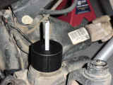
Now
I installed the rear bump stop extensions. You will need to
pull out the rubber bump stop from the cup. If you look on
the cup, you will see 3 indents. I just grabbed mine, and
gave it a sharp tug to the side and it came right out. Now
if it doesn't you will need to stick a thin screw driver up along
side the bump stop and pry down on it at these 3 points to walk
it out.
|
|
Once
you get the bump stops out, you will need a 15mm socket and the
small extension to get the bolt out of the bottom of the cup.
|
|
Once
you remove the cup, replace the stock bolt with the RE bolt and
place the spacer on the bolt, and reinstall the cup. Use an
11/16" socket to bolt these back in place.
|
 |
|
|
|
Reinstalling
the springs in the back is as easy as the front. Once again
you will insert the spring up around the bump stop. I jacked
up the opposite brake disk and inserted the spring.
Yes, once again I could have used a spring compressor to do this,
but the RE arms let the rear flex beautiful.
|
 |
|
As you
can see at full droop the bump stop touches the spring, not bad,
there isn't any real pressure against the stop so it's not going
to come out. |
 |
Once
you have the springs in, all you need to do is install the shocks,
put the wheels back on and let it down.
|
 |
 |
|
You will need a
13mm and a really long extension to get up the mounts again by the
gas tank. It's fun trying to get the two bolts in alongside the
big OME shock. I suggest doing the frame side first, then the inner
one. |
 |
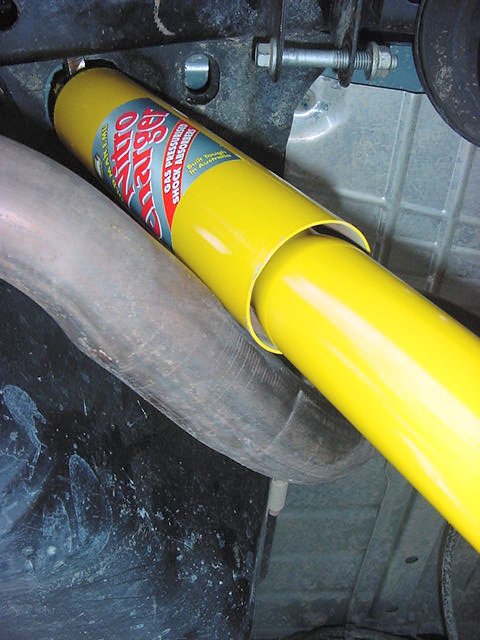
Once I had the shocks
installed I could see that I had a few close contact points with
the shocks. The drivers side would be taken care of with the exhaust
change. |
|
|
|
Now
get back underneath and reattach the anti-sway bar links.
|
 |
|
Once again you will need a 15mm socket, and 18mm
combo wrench to install these. |
 |
Don't forget when
you are adjusting your pinion angles that the front is a double candan
style, so the pinion needs to be in line with the drive shaft, while the
rear is a standard and the pinions need to be with in 1degree of each
other. Adjusting
Pinion Angles.