Main Menu Vehicle Trails Mechanicals TJ/LJ Mods JK Mods Gallery
Front End installation on the RE Long Arm

Front End

Additional Parts:
Anti-seize
6502468 - SCREW, Hex Flange Head, M8x1.25x20, Coil Spring Bracket, Mounting
52005917 - BRACKET, Spring, Coil
(4) 25/64" i.d. 5/8" o.d. brass crush washers for brake lines (Help part: 66272) 
Brake bleed kit
Brake fluid
(2 feet) 5/16" Fuel line
Zip ties assorted
Tools Needed:
Drill
Drill Guide
1/8" Drill bit
5/16" Drill bit
1/2" Drill bit
7/16" Drill bit
5/8" Drill bit
Pliers
3/8" Ratchet
1/2" Ratchet
4" extension
13mm Socket
15mm Socket
16mm Socket Deep Well
19mm Socket Deep Well
19mm Socket
32mm Socket
9/16" Socket
3/4" Socket
15/16" Socket
17mm Combo Wrench
18mm Combo Wrench
5/16" Combo Wrench
7/16" Combo Wrench
9/16" Combo Wrench
3/4" Combo Wrench
1 1/2" Combo Wrench
Phillips Screwdriver
Flat tip Screwdriver
Vise
Floor Jack
Jack Stands (6 tons for the height)
Small adjustable Wrench
T-40 Torx
T-55 Torx
10mm 1.50 tap
Pickle Fork
Pitman Arm Puller
Big Hammer (3lb blacksmith works)


Now that you have the arms installed, you can move on to installing the rest of the items for the front end.


Front Shock Removal:
1. OME LT shocks compared to Factory and Standard OME shocks.

DSC00800.jpg (45238 bytes)

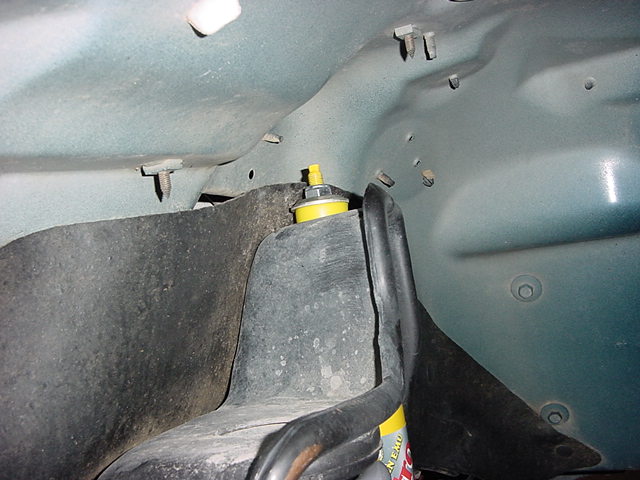
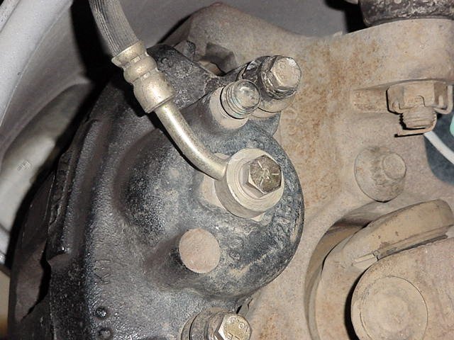
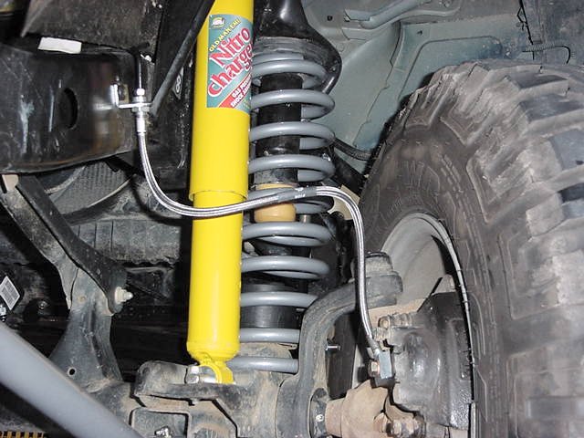
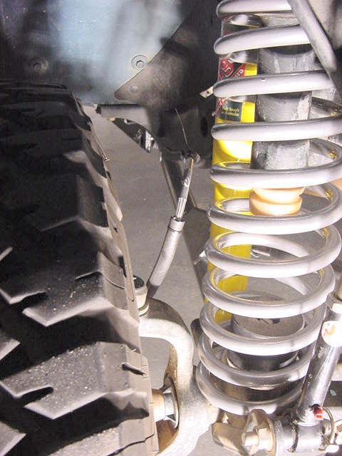
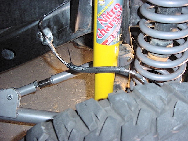
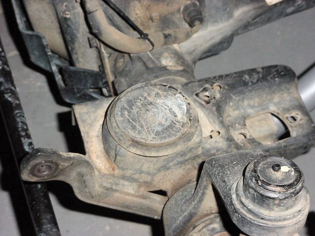
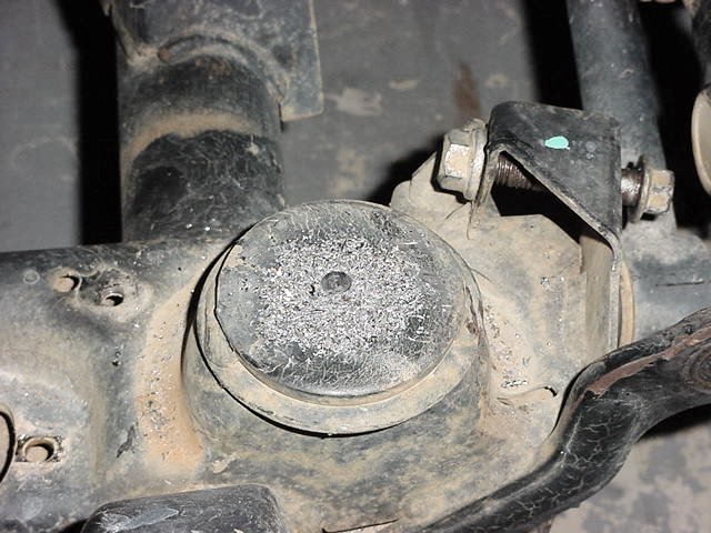
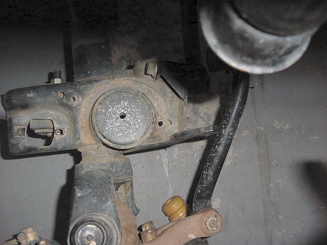
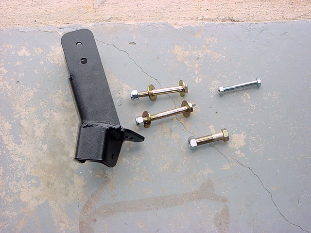
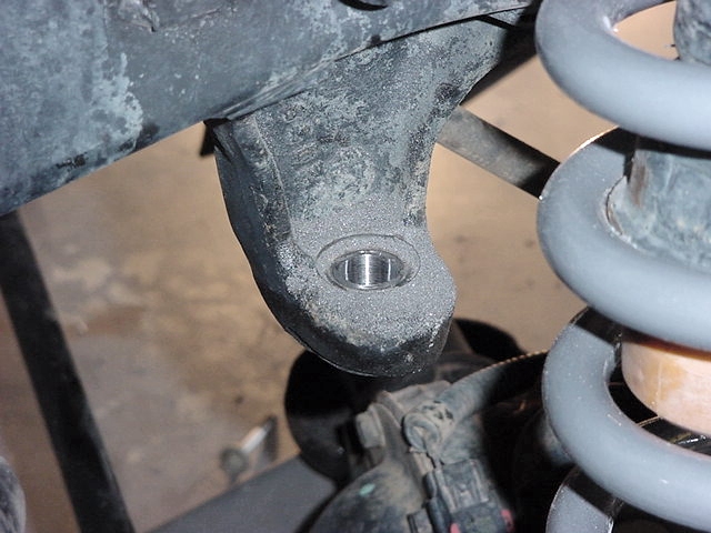
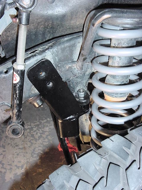
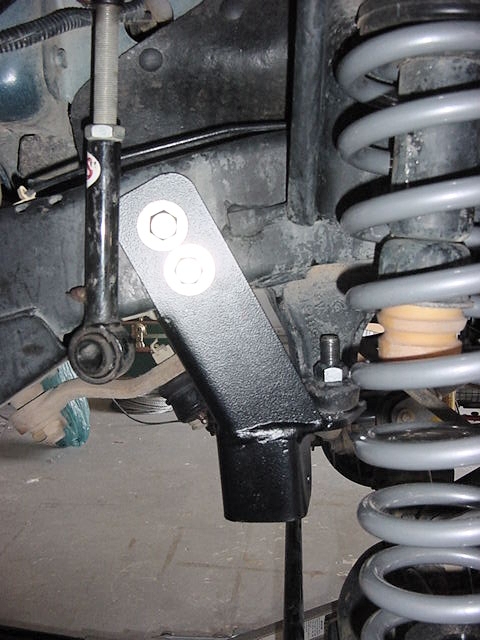
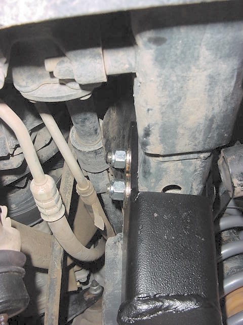
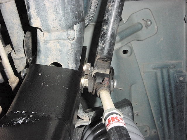
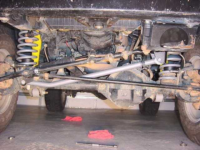
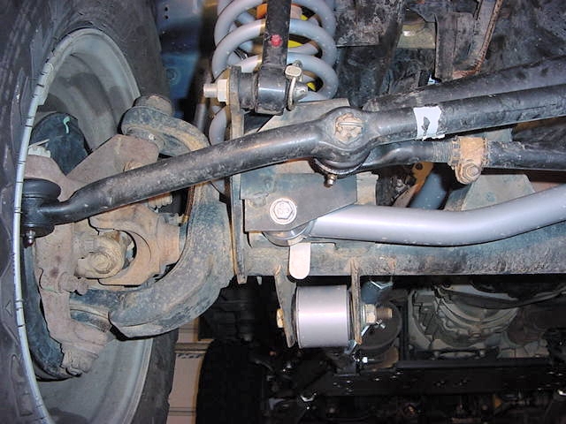
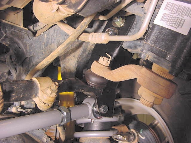
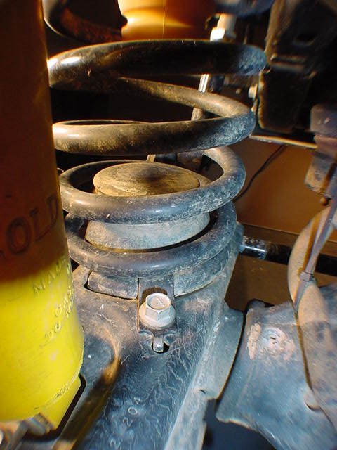
2. The first things you need to disconnect are the sway bar linkage, and front shocks.  I have JKS Quicker Disconnects already installed, so I just pulled the pins and off they came.  For those of you that don't have these you will need a T-55 Torx and a 18mm Combo wrench to remove the bottom bolt.  Place the Floor jack back under the axle to hold the axle.  The front shocks are what limits your droop, so the axle will fall away once you take the shock off, don't worry it doesn't go far, but can make getting the shock off a pain.  I pulled these off before I jacked up the Jeep.

3. The front shocks are held in by a 15 mm nut on the shock tower at the top, and (2) 13mm nuts and bolts at the bottom.  With this being a new Jeep I was able to get the Nut off of the top without any problems.  I placed a ratcheting box end wrench (5/8" worked, but was loose) over the nut, and held the top of the shock tower with an adjustable wrench.     DSC01599.JPG (64835 bytes)
4. Then I removed the lower nuts and bolts.  You will need the 4" extension on the socket to be able to reach the nuts or bolts. DSC01596.JPG (62335 bytes)

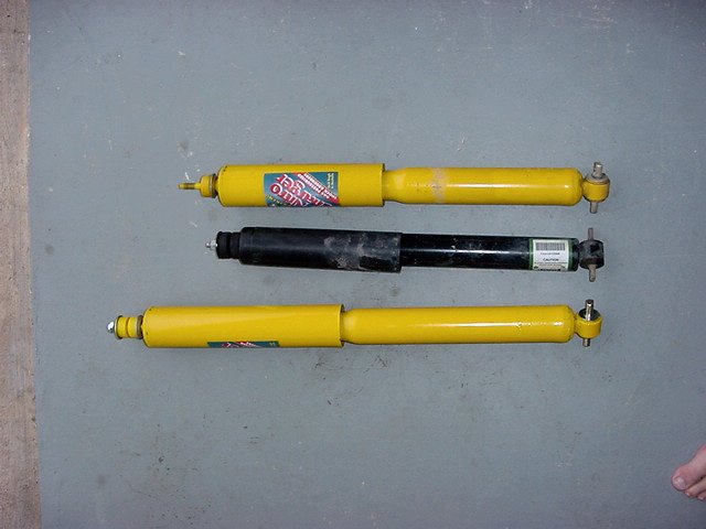
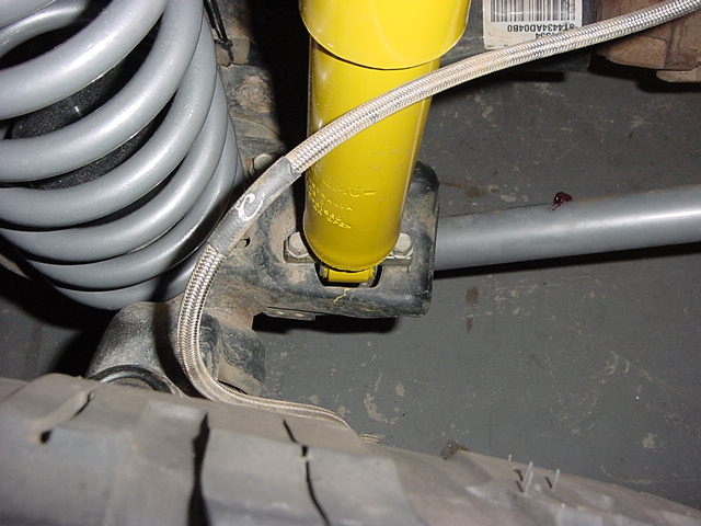
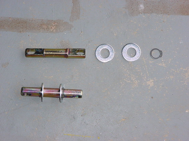
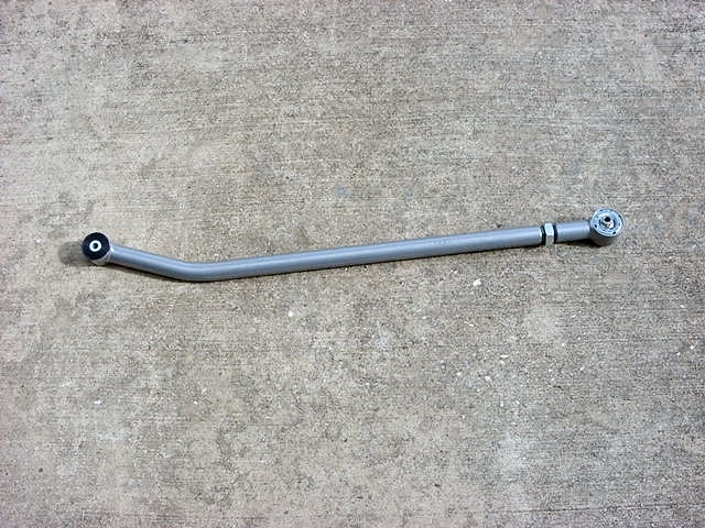
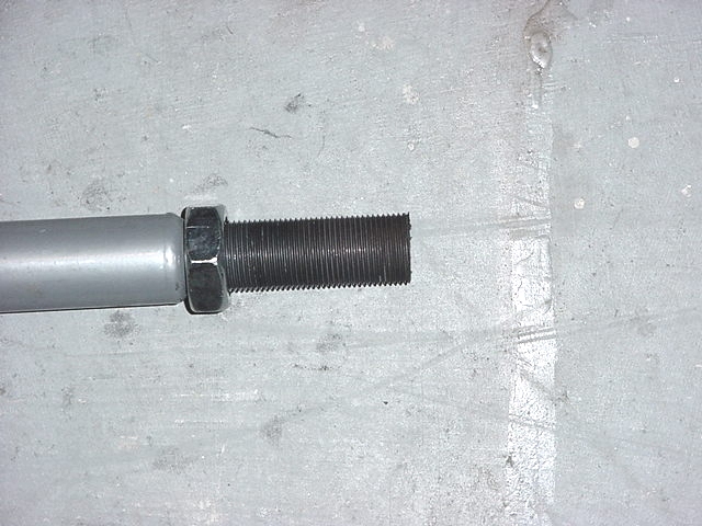
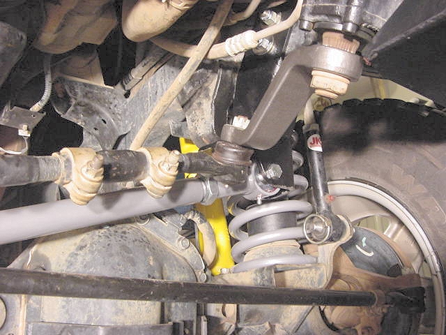
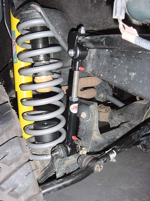
5. Before you install the new OME shocks you will need to install the bar pins.  Pay attention to the bar pins, and don't just dump them into a big pile.  The front bar pins are shorter than the rear and the rears you need to make certain that you put them on the top since both ends have eyes.  
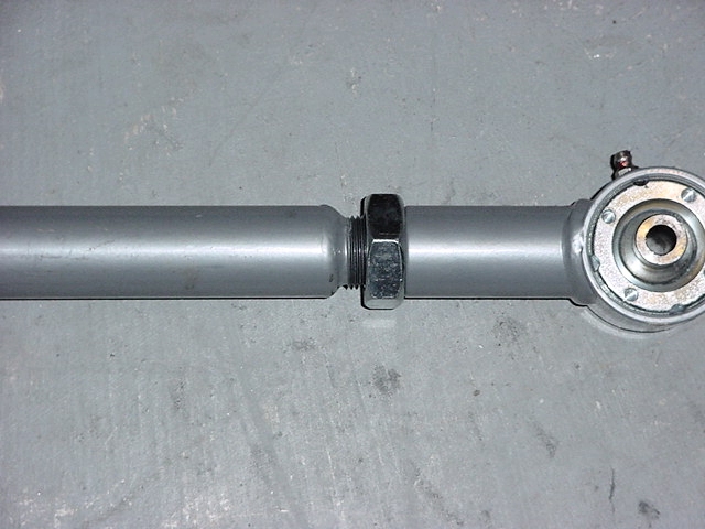
A vise makes putting the bar pins in easy, but if you don't have one take a big deep well socket and put it on one side against the ground, and then drive the bar pin in from the other side.  Simple directions is put washer on bar pin, drive bar pin through bushing, put washer on bar pin, put external snap ring on bar pin.  Make certain the snap ring goes into the groove.  
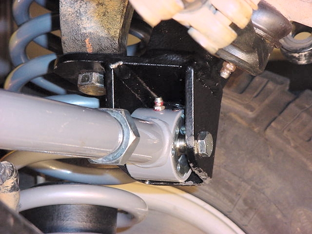
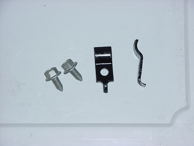
Bar Pin Installation:
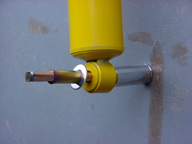
Way #1 (Tools required: External Snap Ring Pliers, 2 Deep well sockets(16mm and 19mm work well), Hammer)
Insert one washer onto the bar pin so that is sits on the shoulder, wedge the end of the bar pin in the bushing, now using a deep well socket as a support for the bushing drive the bar pin through the bushing. It should look like this before you hit it. Deep well on the ground with ratchet side down, then shock bushing, then bar pin sticking up. Drive the bar pin all the way in. Flip the shock over and put the other washer on. Use a set of exterior snap ring pliers, insert the prongs of the pliers into the two holes and gently pry the snap ring open. Open it just far enough to slide down over the bar pin, you need to kind of get it over the round part of the bar pin, vice the flat mounting area for the shock bolts. The snap ring will not go into the grove on the bar pin. Now take another deep well, that will just fit over the bar pin, give the deep well a couple of smacks with the hammer working the snap ring down and into the groove.
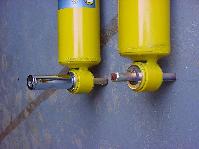
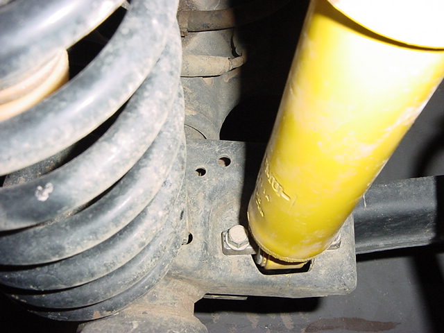
DSC00795.JPG (62462 bytes) DSC00796.JPG (63150 bytes) DSC00797.JPG (62722 bytes)

Way #2 (Vise, External Snap Ring Pliers)
Basically the same way as #1, but you can use the vise to press in the bar pin, and hold the washers in, while you install the snap rings, this way you can actually install them right into the groove, with out having to use a deep well and a hammer. Only problem is you lose that satisfying thunk of the hammer.

6. Installation is just the reverse of removal.  Make certain that you get the upper bushings installed the right way.  The raised section fits into the hole in the spring bucket on the frame.


  N-m Ft. Lbs. In. Lbs.

FRONT Shock Absorber Upper NuT

23 17 -
FRONT Shock Absorber Lower Nut 28 - 250


Brake Lines removal and Installation:

1. Rubicon Express sends you a set of extended length front brake lines.  Some people advocate that you don't need to install these because the factory lines will stretch.  

Dsc00879.jpg (78166 bytes)

2. Well if you look at the end of the line that attaches to the caliper you will notice a small tube running into the caliper via the banjo bolt.  You can bend or break this point.  If you pull on it enough it will eventually bend and we all know exactly when it will break, most likely right after you get out of the mud puddle.  

Dsc00880.jpg (76868 bytes)

3. I first disconnected the hard brake line from the frame bracket with a 7/16" wrench and then the frame bracket with a T-40 torx.  I then removed the banjo bolt with a 9/16" wrench from the caliper and made certain that both brass crush washers came off.  You could reuse these in an emergency, but I have always installed new ones.  

Dsc00881.jpg (73711 bytes)

4. Now all you need to do is install the RE lines.  

Dsc00882.jpg (57379 bytes)

5. First you will need to install the RE line into the new frame bracket.  The bracket points up and the fat end of the line goes into it from below.  Install the C-clip around the fat end with a pair of pliers, make certain that it is fully engaged, these things will fly across the room.  

Dsc00883.jpg (71440 bytes)

6. Now RE does provide another screw incase you need to mount it somewhere else.  I just reinstalled it in the factory hole.  I then connected the hard brake line to the RE with 7/16" and 17mm wrenches.  

Dsc00884.jpg (90714 bytes)

7. Before you fully tighten the hard line make certain that the new brake line is hanging straight down.  If you look carefully at the caliper end of the brake line you will notice how the line runs into the block at an angle.  Make certain that the block is closest to the caliper.  You want to set it up this way so that you can get maximum articulation out of the brake line with out twisting the hard line.  Remember this line is not solidly mounted like the old line was.  So any twist is transmitted to the hard line.  

Dsc01615.jpg (178803 bytes)

8. Now to install the other end onto the caliper.  Make certain that the banjo bolt and area are clean.  Install one brass crush washer onto the banjo bolt, then insert into the end of the brake line followed by another brass crush washer.  Bolt into place on the caliper making certain that the brake line sits flush, and doesn't catch on the small lip by the mount point.  

Dsc01614.jpg (180940 bytes)

9. Repeat for other side.  Now all you need to do is follow the directions on the brake bleed kit and you are done.

Dsc00886.jpg (73084 bytes)
10. One final thing I did was cut 6" sections of 5/16" fuel line.  I then split them down the center and wrapped them around the brake lines at any areas that could rub.  I used 2 small black zip ties to hold them in place. Dsc01662.jpg (160842 bytes) Dsc01664.jpg (220719 bytes)


  N-m Ft. Lbs. In. Lbs.

Caliper Brake Hose Banjo Bolt Front

31 23 -
Combination Valve Brake Lines 
(estimated for hard to flex line connection)
19 14 -


Front Track Bar Removal:
1. First remove the cotter pin and then the 15mm castellated nut from the frame side mount.  Then take a pickle fork and drive it between the top of the track bar and the frame bracket.  Be careful that you get the tines of the pickle fork centered around the taper bolt otherwise it is a real pain.  I found it easier with the flat side of the pickle fork against the frame bracket. Dsc00839.jpg (67376 bytes)
2. Now use a 15mm socket to get the bolt out of the axle side mount.  There is a capture nut on the back side attached to the little tab.  Note: Be careful putting this back in, I stripped mine out, and have waited over 4 weeks for the dealership to figure out the right part number.  Now just slide the bar out and put it off to the side.  Dsc00838.jpg (79231 bytes)


Front Spring Removal:

1. Jack up the vehicle and place jack stands behind the front Lower Control Arm Frame Brackets.  You will need to pick this up fairly high.  I maxed out my 19" throw floor jack and put the 6-ton jack stands up as high as I could get them.  Be careful when you set the Jeep back down.  If you have a winch on the front or a heavy bumper be ready for the rear of the Jeep to shift.  I gained about 4 inches in the back, not enough to affect working on the front, but it did raise and eyebrow when it did it.  Now pull the tires off, I do hope that you already loosened the lug nuts since we started on the front.  
2. Now that we have everything removed we need to get the spring out.  You may or may not need to do this dependent upon how much droop you get out of the axle.  I was able to just pull them out and I was going from an already lifted vehicle so stock springs should come out with no problems.  Let the axle down all the way and place the floor jack under the opposite side brake disk.  Make certain you are only lifting the disk, not any other parts.  Now jack up the disk and compress the spring on this side.  Watch until you just take the frame off of the jack stand.  Once you do that let the jack out until you are resting on the jack stand again.  Now the spring will be loose on the other side, so have a buddy (beer belly friends work the best) put pressure on that disk and now pull the spring out.  Yes, you could use spring compressors to do this, but after having one break a finger for me I don't like to use them.


Front Bump Stop Installation:
1. Now to drill out the lower spring pads for the new bump stop spacers.  You will need 5/16" drill bit and a M10 x 1.50 Tap.  I know that the kit comes with self tapping bolts, but the Rubi's have that heavy metal plate welded to the top of the spring pad, so the Tap makes life easier.   Dsc00846.jpg (62387 bytes)
2. Now all you need to do is mark the center of the spring pad.  Lay the spacer down on top so that it is centered and take a center punch and make a mark right down through the center of the spacer.  When you drill out the hole you need to make certain that you drill straight down.  There is a gap between the top plate and the bottom plate.  If you don't get a straight drill, your holes will be off and you will be unable to get a screw down through the plate.  Dsc00847.jpg (61830 bytes)
3. I drilled the first one fine, but got off on the second one.  I had to cut down one of the screws so that it would fit into the top of the spring pad.   When you drill the holes start with a small pilot hole and work your way up from there.   Dsc00848.jpg (75696 bytes)
4. I drilled an 1/8" and then worked my way up, instead of trying to drill the hole the first time.  Stepping up in drill sizes will also allow you to have a tighter clearance on the actual hole size.  Reason is that if you drill at the 1/2" size (for example) the center point will wander in a small circle as it drill through causing your hole to be slightly larger.  This is why they came up with the pilot point drill bits.  Get yourself some good drill bits.  I used titanium and drilled right through. Dsc00850.jpg (58250 bytes)
5. Use the tap to cut threads in the hole vice the self tapping bolt.  The bolts are actually fairly weak.  Be cautious as you get to the second plate so that you don't over torque and snap the tap.
6. Now don't bolt on the spacers yet or you won't be able to get the springs in. 


Front Track Bar Installation:
1. Now you will need to install the RE track bar drop bracket and adj. front track bar. Dsc01590.jpg (215236 bytes) Dsc01584.jpg (166543 bytes)
2. I first needed to widen the original frame mount hole to 5/8" to accommodate RE's bolt.  This is a no going back point.   You will need to have the front suspension drooped as far as possible and probably a 1/2" angle drill to get into this place.  I decided to just grind it out with my Dremel.  It took a while, but the hole came out right at 5/8".   Dsc01583.jpg (159066 bytes)
3. Now you will need to get the RE bracket up and around the frame.  I spent a while banging this beast in with my hammer and a pry bar to get it to line up.  I bolted it into the factory frame bracket, and gave it a few taps with the hammer, checking to make certain I was still tight.  This bolt and nut is a 15/16". Dsc01589.jpg (182498 bytes)
4. As you can see the nuts sit pretty close to the steering shaft and power steering lines.  You really can't get a drill bit in here to drill these holes.   Dsc01588.jpg (163834 bytes)
5. I used a drill guide with an extended length 1/8" drill bit to drill straight through to the other side.  I did manage to hit fairly close to center this way.  After you get your initial pilot holes drilled, you can just step up in sizes on the drill bits until you drill your final 1/2" hole. Dsc01606.jpg (185951 bytes)
6. Now run your bolts through and tighten everything up.  You will need a 3/4" wrench and socket to tighten these up. Dsc01585.jpg (166083 bytes) Dsc01587.jpg (165702 bytes)
7. One thing I noticed right away was how close the anti-sway bar was to the bolt heads on the RE bracket.  While you really can't see it in this picture there is just enough room for the anti-sway bar to move past these bolt heads.  I will keep an eye on it in the future.  The Currie Anti-rock will solve this problem. Dsc01591.jpg (169817 bytes)
8. With the drop bracket installed, I decided to test fit the new adj. front track bar.  I centered the axle and took a quick measurement from bolt hole to bolt hole. Dsc01611.jpg (201834 bytes)
9. My length ended up being 32 5/8".  Well I screwed the end of the RE track bar all the way in and couldn't get it shorter than 32 7/8".  Okay, that's a problem.  I did have over 1/4" of thread showing on the track bar, so I took it all the way off to see if something was catching inside.  Nope the length of threads were just to long.  So I used my Dremel to cut off 1/4" and that solved the length problem. Dsc01613.jpg (163582 bytes)
10. I then installed the zerk fitting in the Johnny joint end.  You will need a 5/16" wrench. Dsc01610.jpg (147476 bytes)
11. Now insert the Johnny joint end into the frame bracket and install the bolt.  Don't tighten down yet.  Make certain that your zerk is pointed down, otherwise you will need to change it out for a 90degree zerk so that you can grease it. Dsc01612.jpg (166763 bytes)
12. Now push the axle end of the track bar up into the bracket and insert the bolt.  If the holes don't line up just perfect you can push and pull on the axle to get it to move slightly.  Be careful screwing this bolt into the capture nut on the back side. Dsc01680.jpg (182868 bytes)
13. The lock nut on the track bar will be tightened down later.  You will need a 1 1/2" wrench for this.  


  N-m Ft. Lbs. In. Lbs.
BALL STUD NUT (TRACK BAR TO FRAME) 81 60 -
BOLT AT THE AXLE BRACKET (TRACK BAR TO AXLE) 47 40 -
BOLT AT THE AXLE BRACKET (RE's INSTRUCTIONS)   65 -
JAM NUT REAL TIGHT


Drop Pitman Arm Installation:
1. Now to install the drop pitman arm.  Since we already dropped the track bar with the RE bracket, we need to realign the drag link with the track bar.  The drop pitman arm is what accomplishes this.  As you can see from the picture it adds about 2" of drop. Dsc01656.jpg (173874 bytes)
2. The other reason we need to drop the pitman arm is so that we can decrease the angles at both of the steering knuckles. Dsc01660.jpg (173656 bytes) Dsc01659.jpg (182191 bytes)
3. First we need to remove the drag link and the factory pitman arm.  First remove the cotter pin from the nut holding the drag link to the pitman arm.  Next remove the nut with a 19mm wrench or socket.  I then used a pickle fork to remove the drag link from the pitman arm.  Make certain that you don't hook the rubber boot.  You don't want to tear this.  Once you get the drag link disconnected, use a 32mm socket to remove the nut holding the drag link on.  This came off surprisingly easy.  Now attach the pitman arm puller and pull the pitman arm off.  This is not that easy, you will tighten and loosen it quite a few times, use some lubricant on the splines. Dsc01655.jpg (180653 bytes)
4. Now install the new pitman arm.  Make certain that you get it tapped up onto the threads really good.  I used the 32mm socket, and the hammer to tap the arm on.  Now install the lock washer and nut.  Once you have the arm on, reinstall the drag link. Dsc01661.jpg (207962 bytes)


  N-m Ft. Lbs. In. Lbs.

PITMAN ARM SHAFT

251 185 -
DRAG LINK BALL STUDS 74 55 -


Front Spring Installation:
1. After you get that done, it is time to put in the new spring.  I was able to slip the spring right in, but if you can't I included a quick way to do it.  Put the floor jack under the opposite brake disk and jack it up as far as you can, but be careful you don't lift it off the frame.  Now insert the spring up around the bump stop cup.  I was able to do this without spring compressors.  The RE arms allow the front end to really flex.  Before you slide the spring over the top of the spring perch, you will need to insert the new bump stop into the bottom of the spring.  Watch your fingers.  Now push the spring completely onto the spring perch.  Once you have the spring on, you will need to install the bolt in the bump stop spacer and tighten it down.  A 9/16" socket fits the bolts.  
2. Rotate the coil until the pigtail (end of spring) slides into the indent in the bottom spring pad.  Repeat on the other side.  
3. I now installed the spring clips and bolts on each side.  The front OME shocks have so much travel that they will unseat the springs by about 3 inches, so this is good insurance that they don't move around.   DSC00394.JPG (60887 bytes)
4. Locate the 2 holes on the spring pad right behind the shock mount.  The pigtail on the clip goes in the rear hole.  I did need to bend one of the pigtails down a little to get it to line up. DSC00392.JPG (61492 bytes)
5. Wait to fully tighten them down until the vehicle weight is back on the springs.  You will need a 13mm socket or combo wrench to tighten these bolts up.  These are body bolts, so take a little to get them started in the hole. Dsc00781.jpg (65750 bytes)


  N-m Ft. Lbs. In. Lbs.
FRONT SPRING RETAINER CLIP AND BOLT 21 16 -


Front Sway bar end links:
1. Now reinstall the anti-sway bar end links.  You will notice that this pulls the anti-sway bar below horizontal.  The effective range of the anti-sway bar when the vehicle is on the ground is +/- 20degrees from horizontal.  The preferred range is 20 degrees above to 5 degrees below horizontal.  I extended mine to about 10 1/2".

I didn't install the RE Quick Disconnects on my Jeep.  I will update this in the future when I install them on my friends along with my old kit.

Dsc00853.jpg (77489 bytes)


  N-m Ft. Lbs. In. Lbs.
FRONT STABILIZER BAR LOWER LINKS 95 70 -


ADJUSTMENTS:  (Some of these need to be done or rechecked once entire suspension is installed.
Axle Centering:

Centering the front axle is easy. You don't have to bounce or anything.

First measure from the frame to the rim/ or tire as close to right above the axle. This will eliminate the possibility of the body being off center on it's mounts and having a slight turn in the tires. Now once you have this measurement, you will know how far you need to move the axle.

Second, once you have this measurement. Adjust the Track bar to 1/2 the difference in distance.    Now all you have to do is turn the front wheels and the axle will move underneath the frame.  Once the track bar lines up with the axle bracket, install the bolt and nut.  Then just drive it around and remeasure.

Repeat above as necessary.  

 
Pinion Angle:
Don't forget when you are adjusting your pinion angles that the front is a double candan style, so the pinion needs to be in line with the driveshaft, while the rear is a standard and the pinions need to be within 1degree of each other.  Adjusting Pinion Angles.
 
Steering Alignment:
Once you have gotten everything installed you will notice that the steering wheel is off.  Your toe in will also be off, but that is a little hard to see.  You will need to get an alignment to set everything straight.  With the steering wheel off it is difficult to drive it, lots of bump steer that can quickly lead to death wobble.  Real scary the first time.  You will need to adjust the drag link to recenter the steering wheel.  Loosen the two nuts on the adjustment with a 15mm wrench and adjust the drag link out until the steering wheel is centered up.  You may need to drive it a couple of times and adjust as necessary.  Quick primer on Jeep Alignment. Dsc00870.jpg (66682 bytes)
 
Headlights:
Now you will also need to adjust your headlights.  Headlight adjustment.


  N-m Ft. Lbs. In. Lbs.

DRAG LINK CLAMP

49  36  -


Troubleshooting:

Bump Steer:  Caused by improper relationship of drag link, and track bar.  To correct, center axle again following the instructions supplied with the track bar.  Next determine the neutral position of the steering wheel.  Adjust the drag link to center the steering wheel.

Next Page

Skid Plate
Brake Line Standoffs
Long Arms
Front End
Rear End
Additional Parts
Magna-Flow Muffler
Tom Woods Drive Shaft
Issues
Final Notes

This page last updated: 16-Apr-2008

Content and Design © 2002-present WanderingTrail,  Ronald Seegert
Common Sense and Safety should always be observed when working on your vehicle or doing modifications. Jackstands, wheel blocks, disconnecting the battery are a few of the basic safety precautions that should be used and may not be mentioned in the write ups on this site. You are responsible for your own installation, these write ups are a helpful guideline and should not be taken as an official installation instruction. My write up may be different from the kits currently out there, so alwasy double check the manufacturers installation instructions when installing anything. I try to keep the site up to date with changes that have occured as I discover them, but may not have the latest unless someone lets me know. If you feel that an install is above your capabilities after reading my write ups, I recommend getting together with a club and getting some help. Only a few times have I needed to employe some actual help from a shop to get something done. Usually welding or A/C work. While I have spent many years working on mechanical systems, I am not an expert, nor do I pretend to be one. I hope these write ups have been useful to you.
All trademarked names & logos are property of their respective owners
This site is in no way associated with Stellantis.
Jeep is a registered trademark of Stellantis.