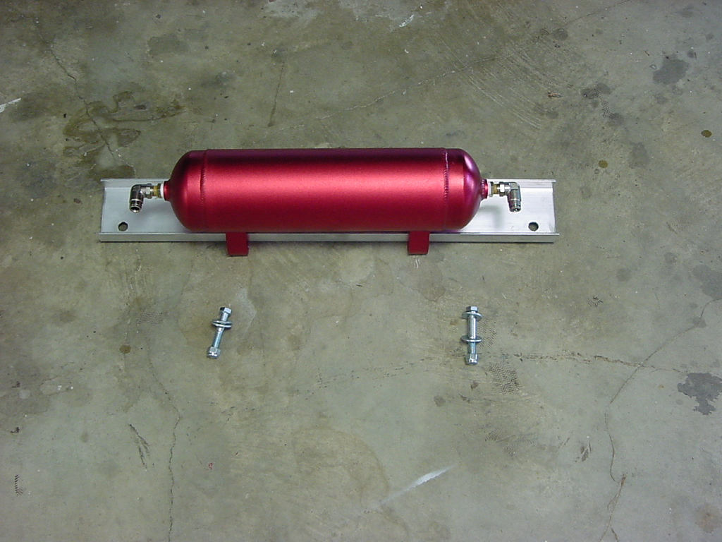
Mounting the Tank |
| The tank comes already mounted to the bracket, all you need to do is mount it to the cross members. |
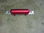 |
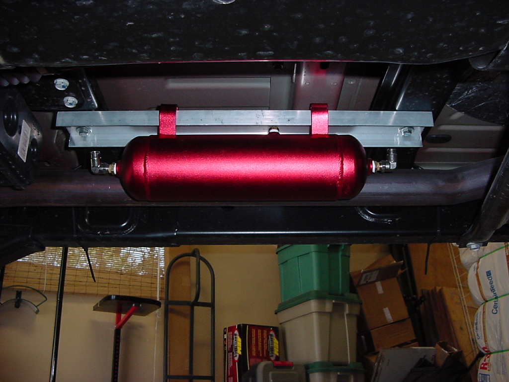
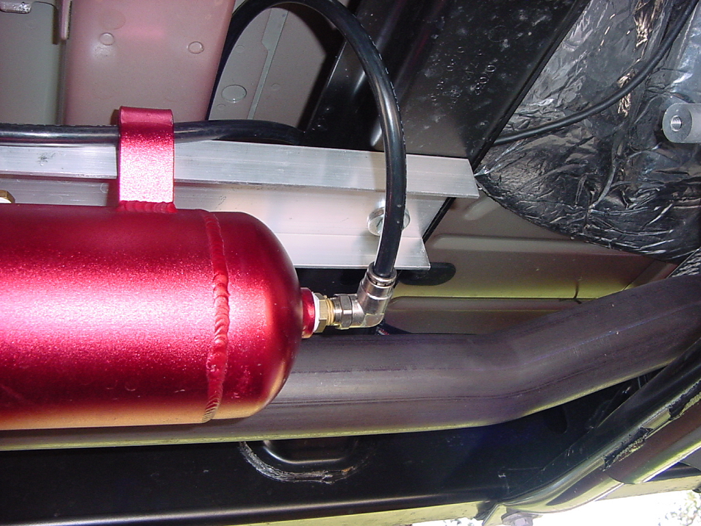
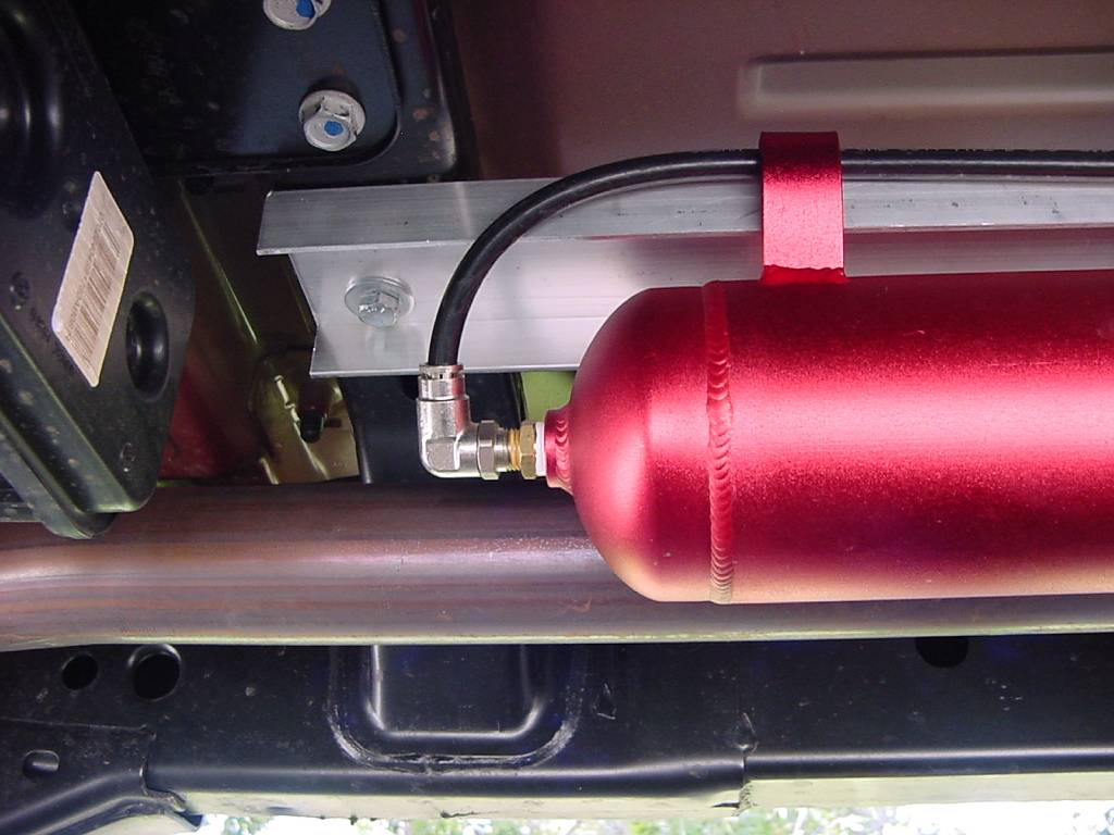
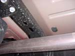
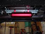
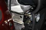
The tank mounts alongside the exhaust pipe between the two cross members. The cross members already have holes drilled through them. The tank will sit offset away from the muffler on the bracket.
Note: The bolts that hold it up are different lengths. The longer one goes through the rear cross member. It is difficult to hold up the tank by yourself and install the bolts so I used a floor jack to hold up the tank and install the bolts. |
 |
| Use a 9/16" combo wrench and 9/16" socket. |
 |
| |
AIRLINE TRIMMING TECHNIQUE: |
| The airline and fittings selected for this kit are of the highest quality. These fittings are designed to allow the airline to be pushed into the opening and then give the line a slight tug to seat the internal o-ring. Although these fittings are high quality, it is possible to have a problem if the airline is not trimmed properly before it is inserted into the fitting. Most problems will be an O-ring that is not sealing due to damage by the airline. It is of the utmost importance to utilize the tubing cutter to insure a clean straight cut. Also, make sure there are no burrs or edges on the airline that may damage the o-ring upon installation. Using the provided tube cutter, trim the airline so that the cut is square to the line itself, to great of an angle will cause a leak. Insert the line into the opening of the fitting. Once a slight resistance is met, a gentle but firm push will result in the line inserting a slight bit further. Give the line a tug, if it is seated properly, the line will not come out. To remove the line, simply push the outer ring of the push fitting towards the fitting while providing a slight pull on the line, once released it will allow the line to be removed. Pulling to hard on the line will not allow it to release. |
| |
| Running the Lines |
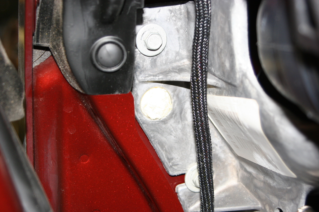
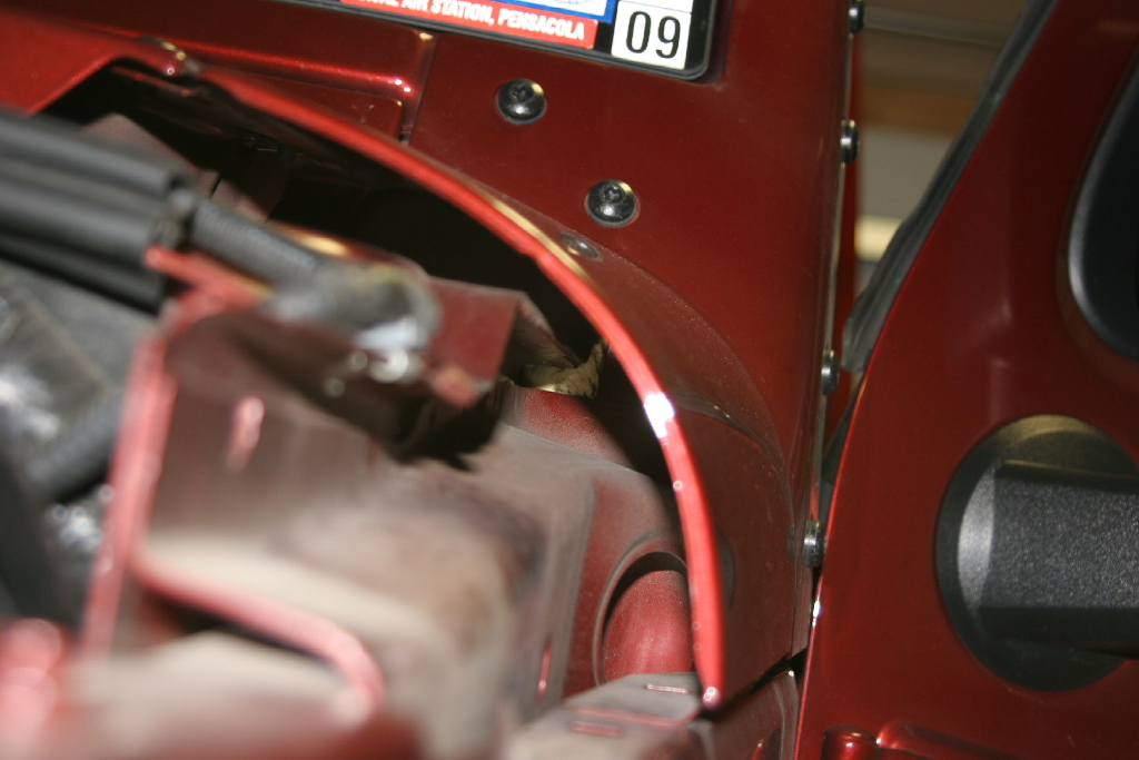
| Note: Your biggest concern when running the lines is keeping them away from the heat of the muffler. The lines are nylon, so will melt if placed to close to the muffler. I ran the lines along the top of the cross members and to the outer edge of the frame, then up long the inside of the fender well. There is a space right behind the fender liner that you can send all the lines up. You need to keep the lines and wiring harness away from the precat's that near the frame. |
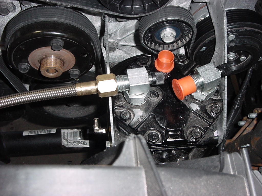
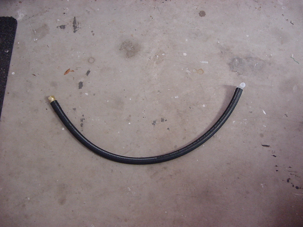
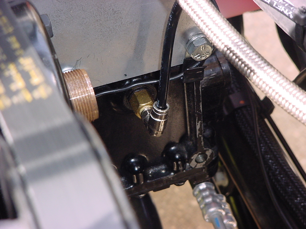
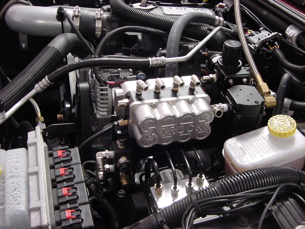
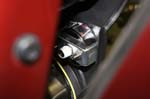
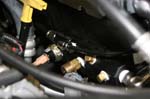
| Attach the steel braided compressor discharge hose to the compressor outlet and route around the passenger side and firewall to the air/ oil separator attached to the ACU bracket. Use a 7/8" Combo wrench. |
|
|
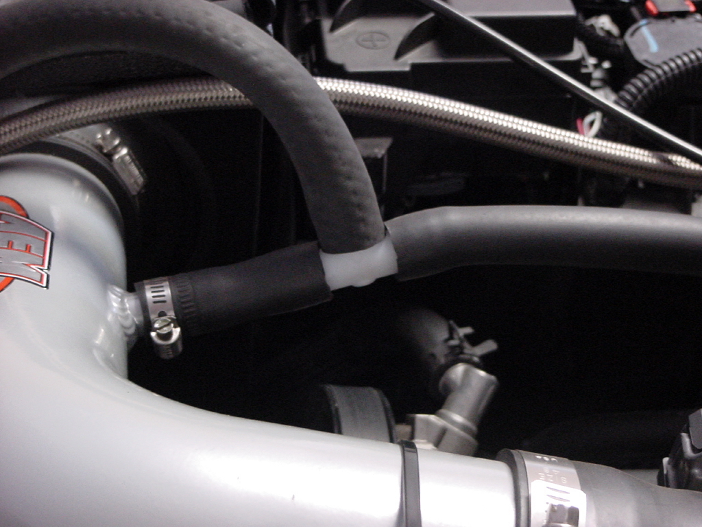
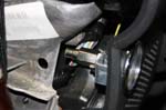
| Attach the Suction hose to the suction side of the compressor. The suction line will tap into the valve cover line. |
|
|
|
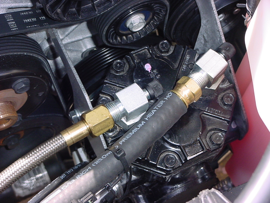
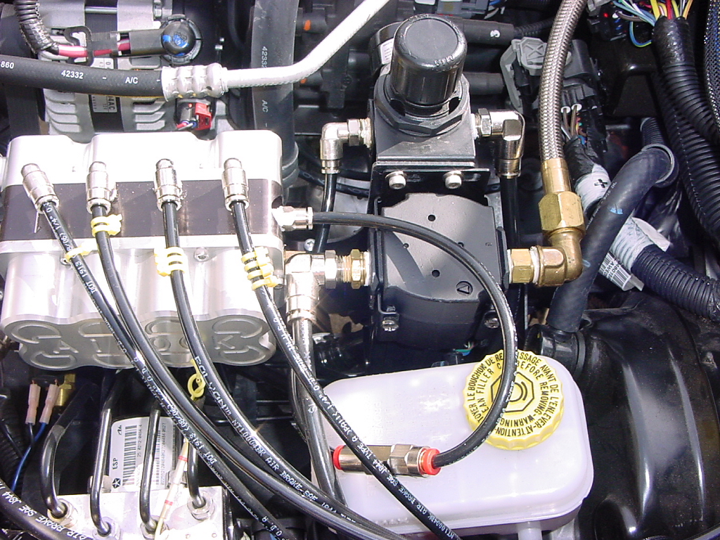
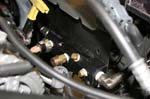
| Install a 3/8" air line from the air/ oil separator to the air tank. |
|
| I routed my line across the firewall and down the passenger side firewall, then back along the the frame and over the cross member to the air tank. I routed the return line the same direction back to the manifold. This will keep the lines away from the pre-cat that sits close to the drivers frame rail. |
|
|
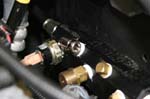
| Install a 1/4" air line from the air/ oil separator drain to the compressor oil return port. You can route this right back along the compressor discharge hose. |
|
|
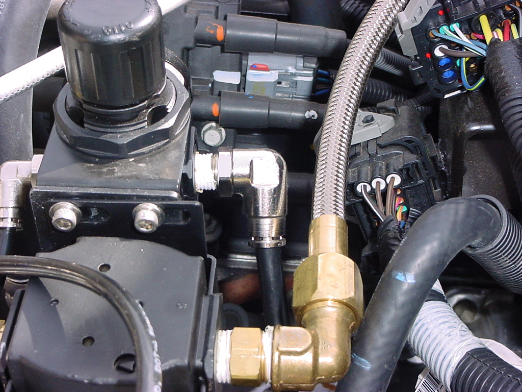
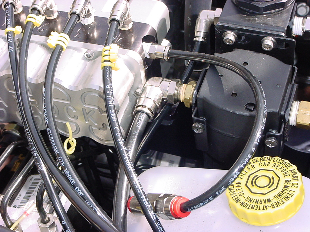
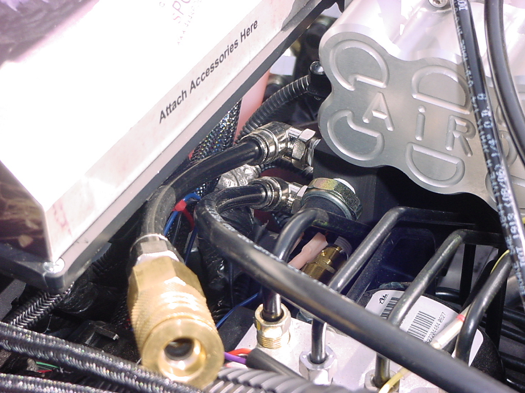
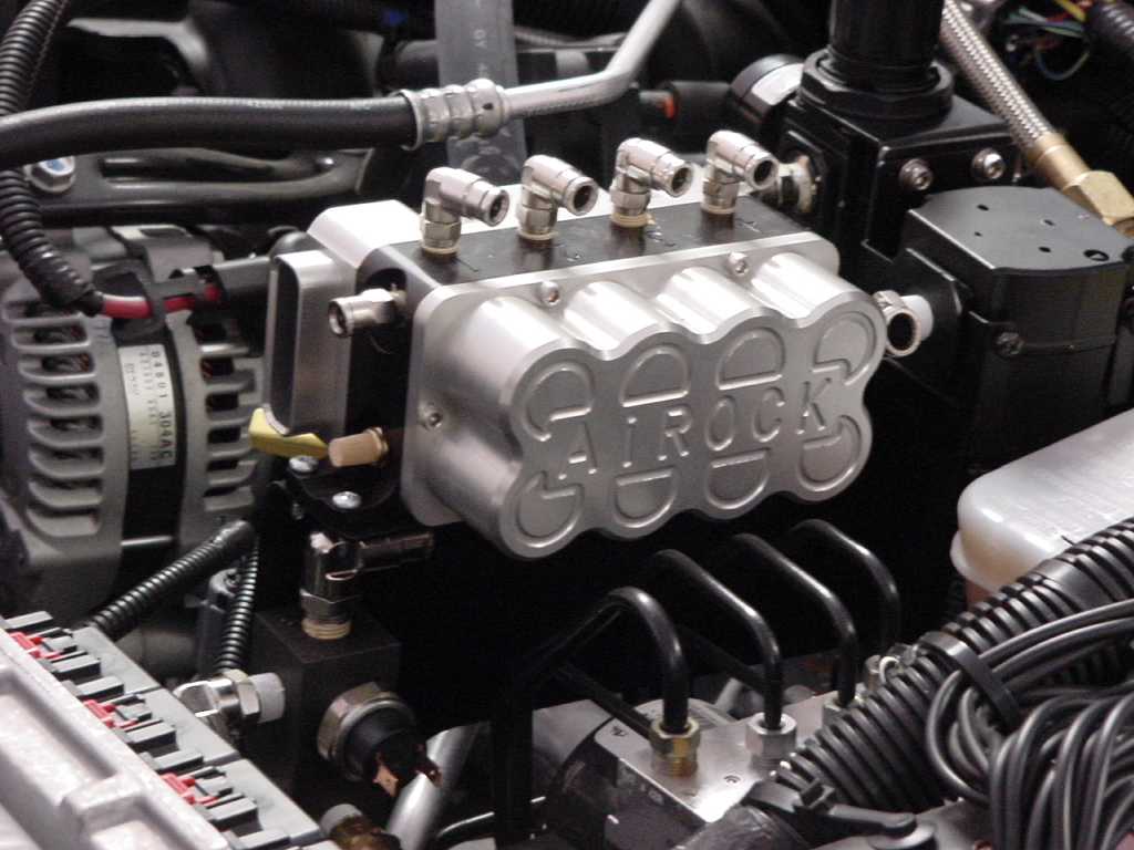
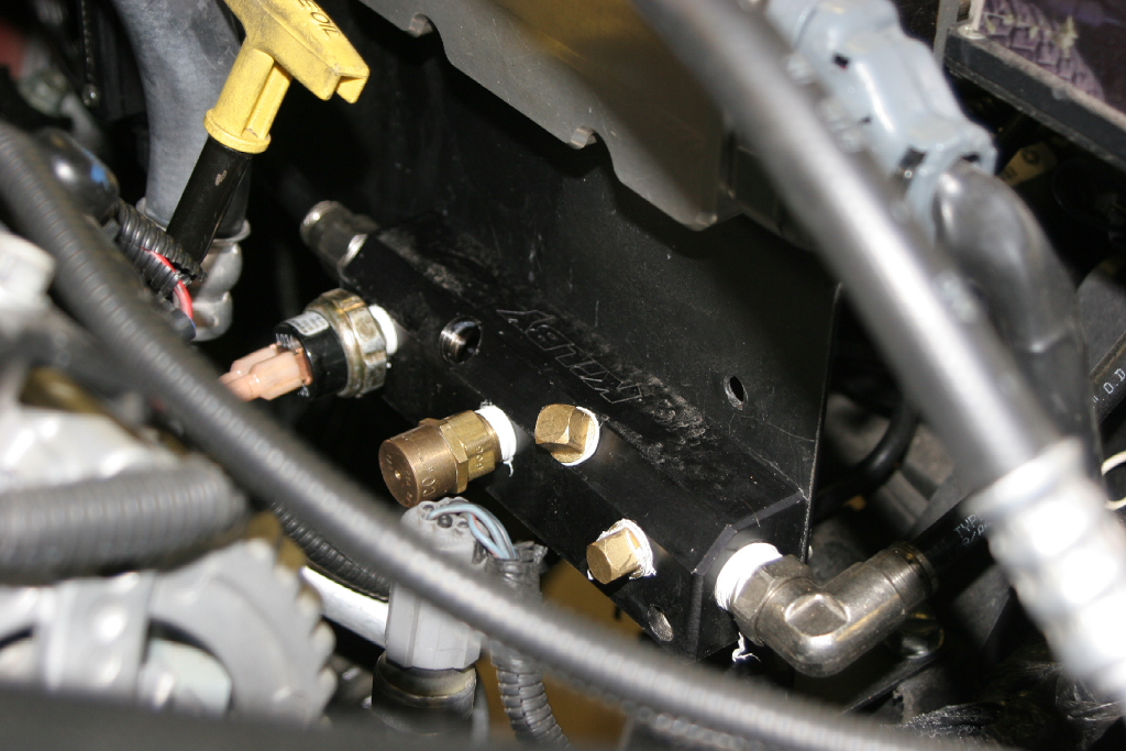
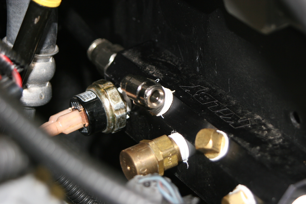
| Install a 3/8" line from the manifold to the pressure regulator inlet. |
|
|
| Install the ACU onto the ACU bracket with the supplied bolts. |
|
|
| Install a 1/4" air line from the pressure regulator outlet to the inlet on the ACU. |
|
|
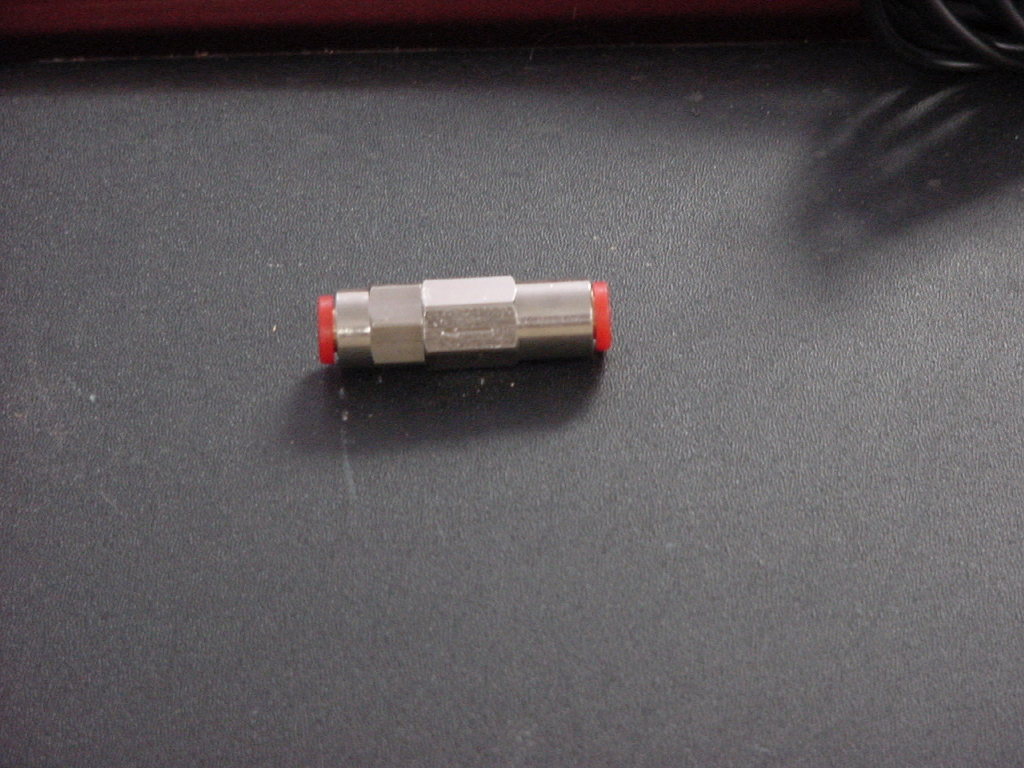
| Cut the previously installed 1/4" line in half and install the 1/4" check valve with the arrow pointed towards the ACU |
|
|
| |
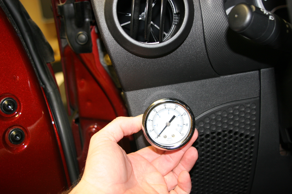
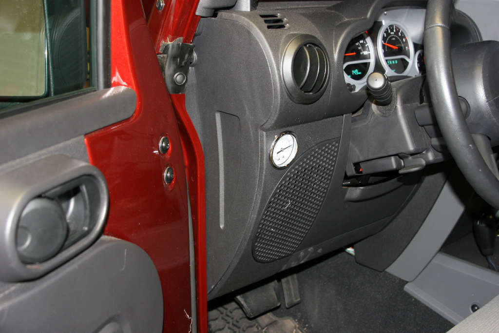
| Air Guage Installation: |
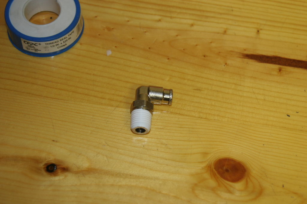
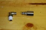
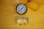
| I had a 2" 0-160psi back mounted gauge panel gauge from Kilby sitting in the drawer so I decided to install it in the Jeep so that I could see what pressure the system was at. I believe ORO sells a gauge kit, but have not seen the installation procedure for it. This one works well though you do have to peer around the edge of the steering wheel to see it. I did have some old fitting laying around so I used a 90deg swivel elbow and female fitting for the 1/4" tubing between the manifold and guage. |
 |
 |
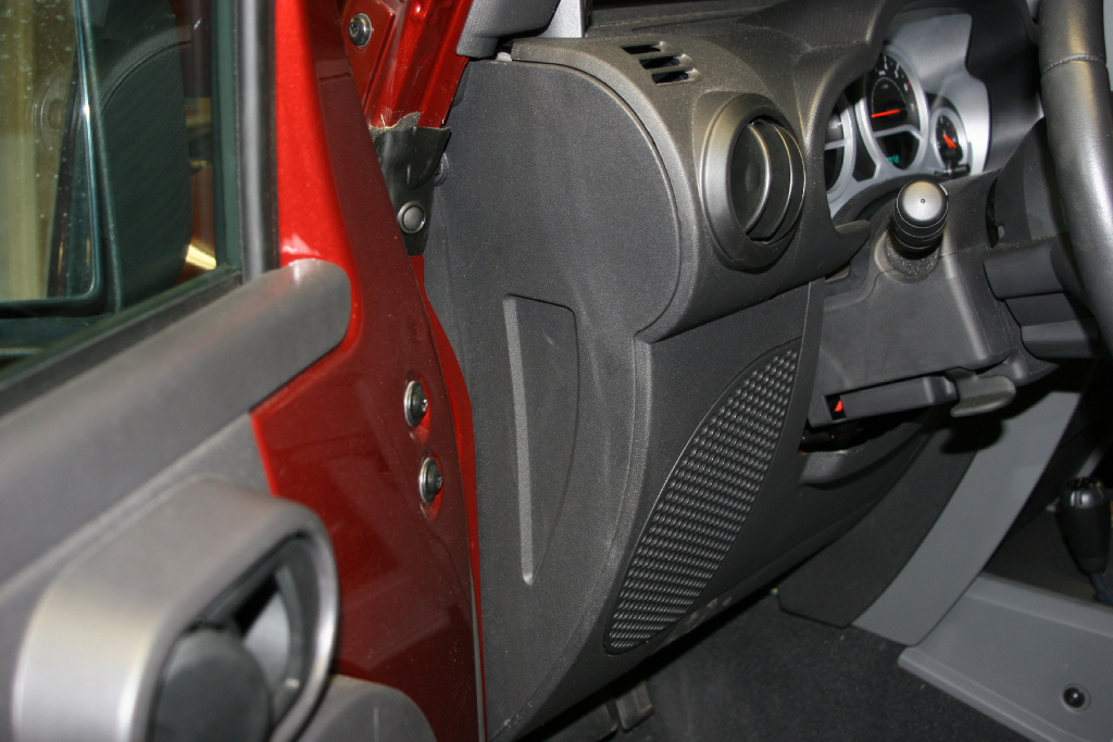
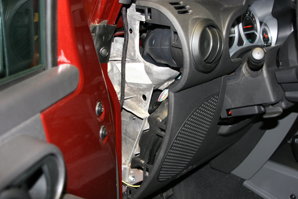
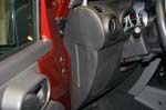
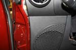
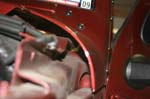
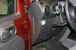
| 1. Remove the side panel of the dash. It pulls out with a little pressure. It's just in with some plastic clips. |
 |
 |
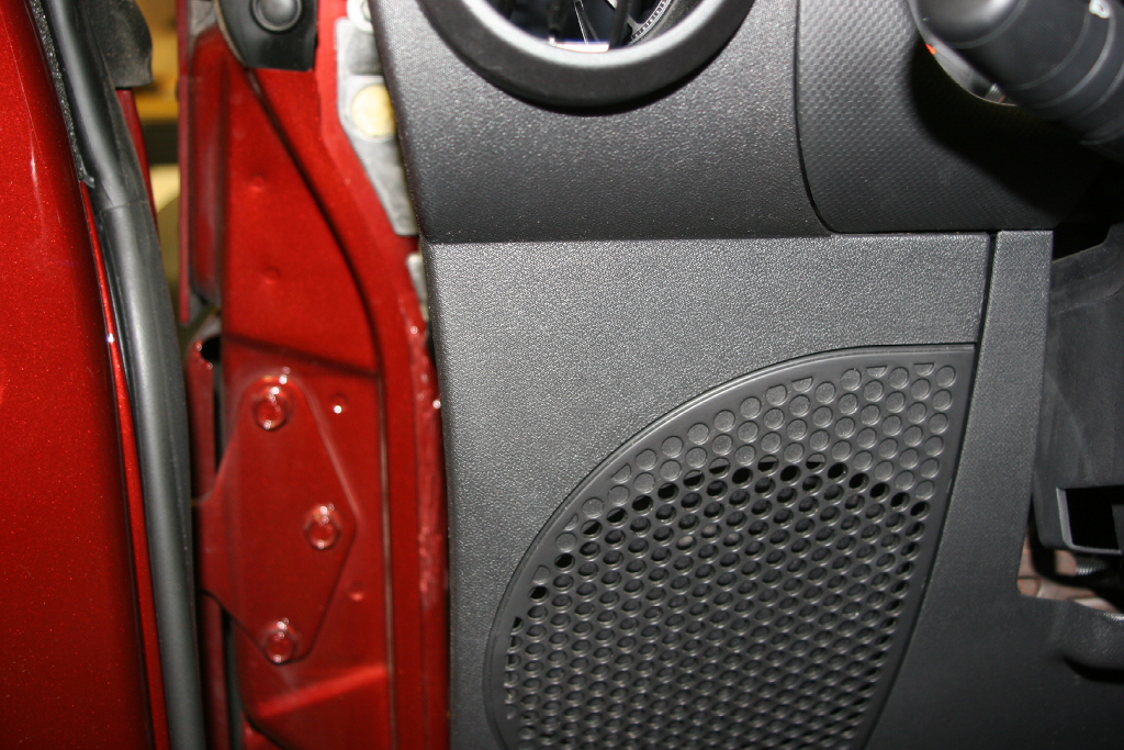
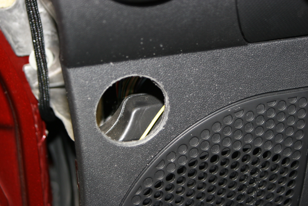
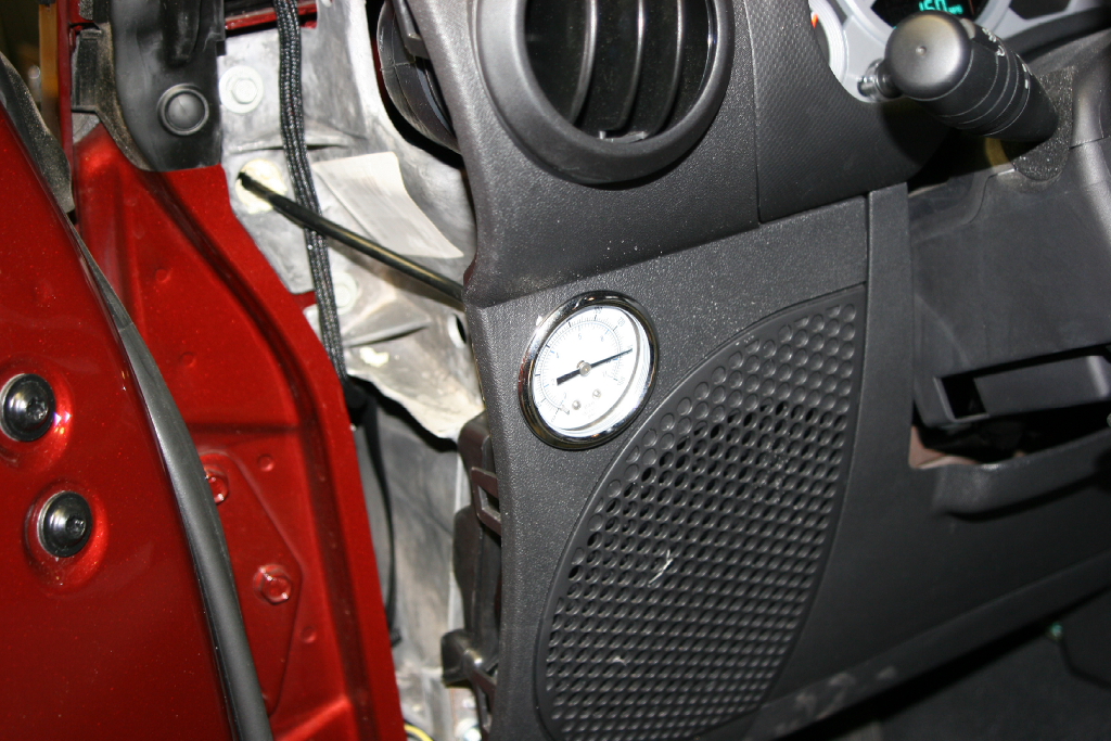
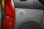
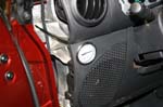
| The guage will be going right above the speaker grill. It's a tight fit and you only get to drill once. |
 |
 |
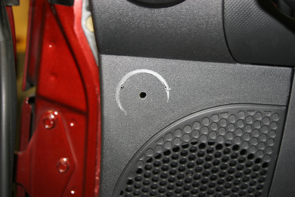
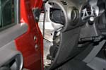
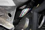
| Note: When you drill with the big 2" hole saw, be careful of the wiring bundle behind the dash. |
 |
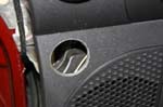
| 2. Drill a hole in the dash using a 2" hole saw. |
 |
 |
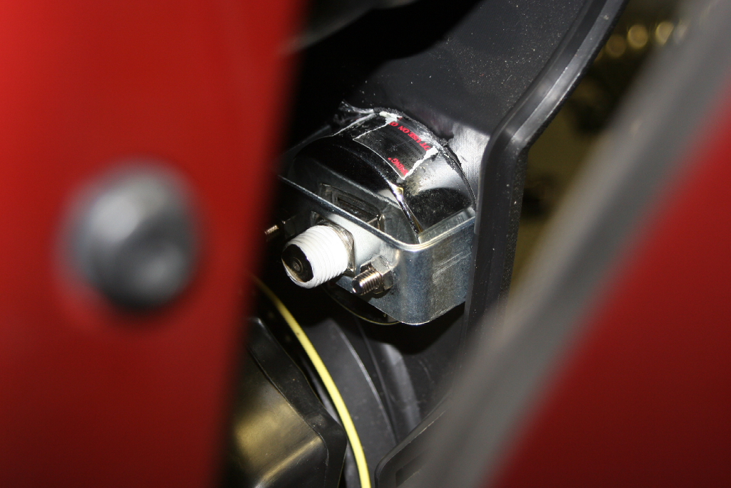
| 3. Install the gauge in the hole. Tighten the nuts on the hold down bar. Wrench size depends upon your nuts, normally a 1/4" or 3/8" nut. |
 |
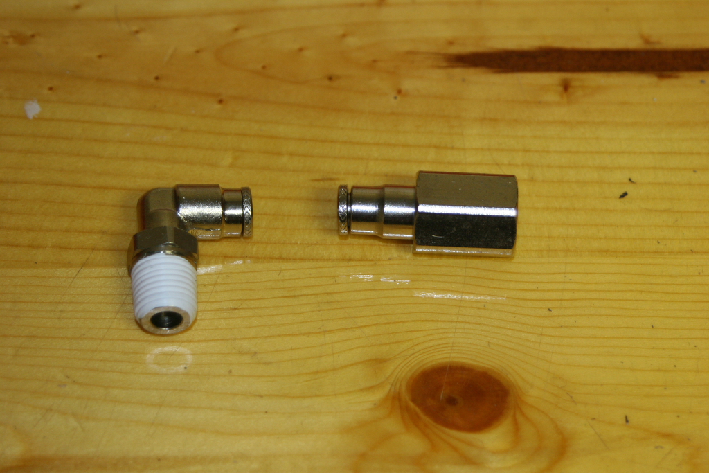
4. Install the female 1/4" tube fitting on the end of the pressure gauge. You will need a 5/8" wrench.
Note: This may be a 3/8" fitting with the ORO kit. |
 |
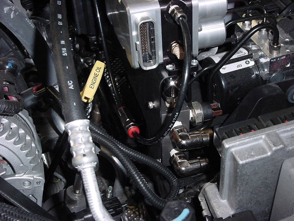
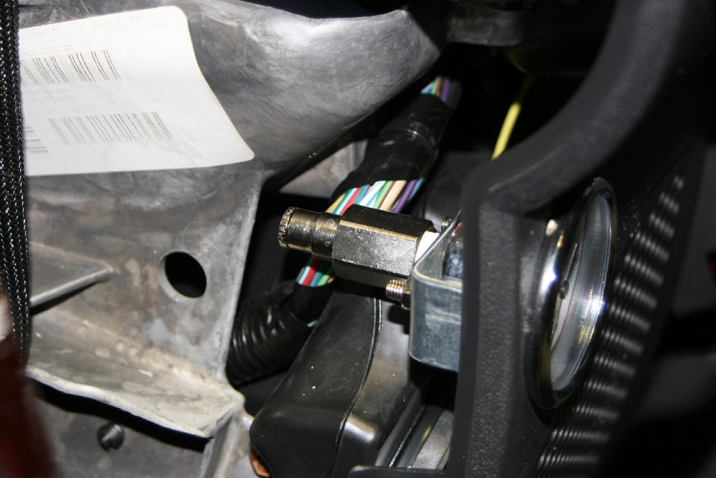
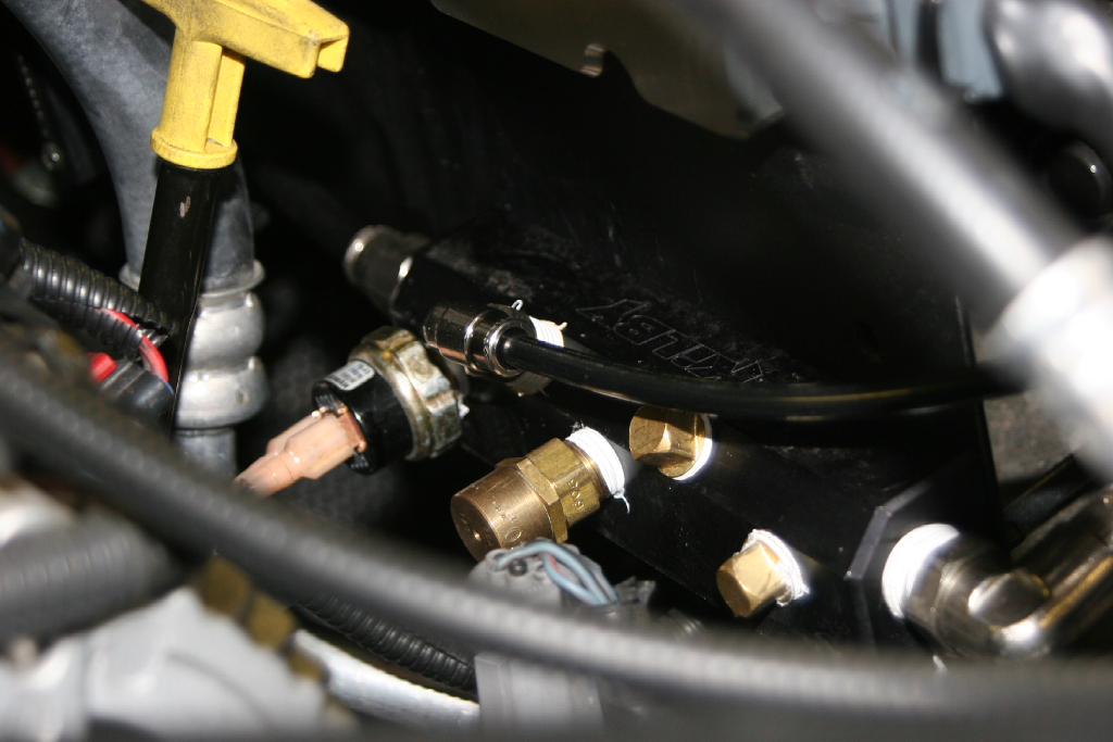
5. Install the 1/4" 90deg fitting in the air manifold.
Note: If you are using ORO's gauge, you may be installing a T fitting in an air line. |
 |
 |
 |
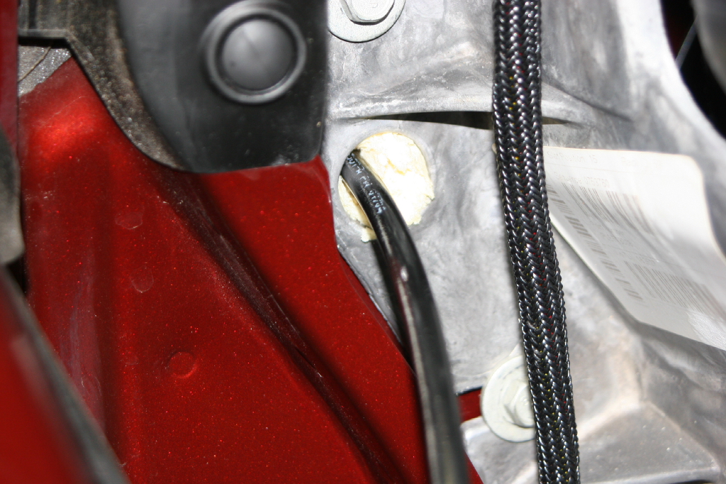
| 6. Poke a hole through the insulation filling a hole between the dash and cowl. A phillips screwdriver does the trick well. |
 |
 |
| 7. Feed the air tubing through the hole. It's easier from the drivers seat area. |
 |
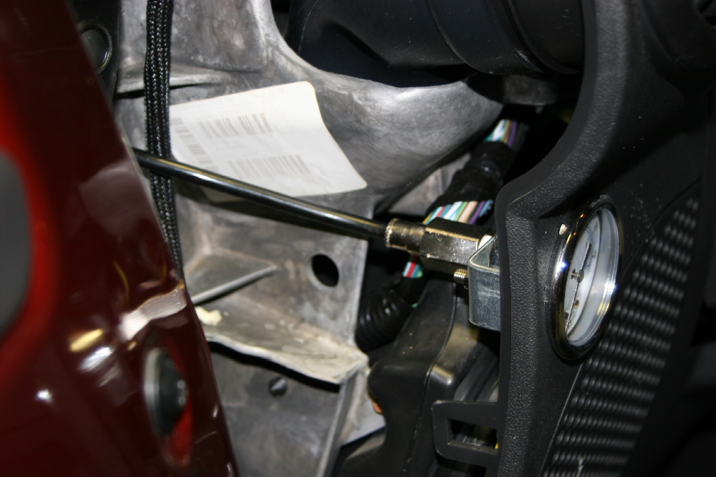
| 8. Connect the air line to the manifold fitting. Trim off the excess length and connect to the pressure gauge fitting. |
 |
 |
| 9. Pressureize the system and check for leaks. Then reinstall the dash panel. |
 |
 |