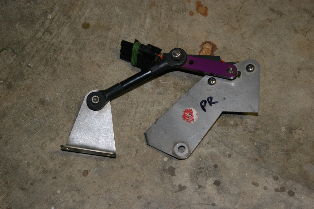
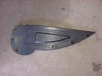
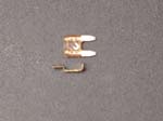
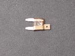
| Install the front height sensor’s: |
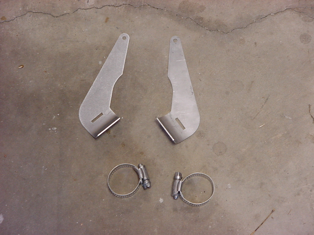
Frame Brackets (ignore the small brackets) |
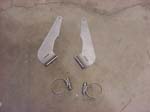
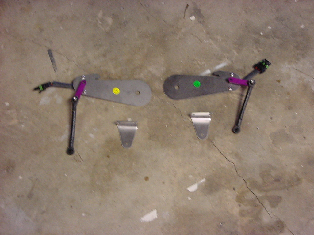
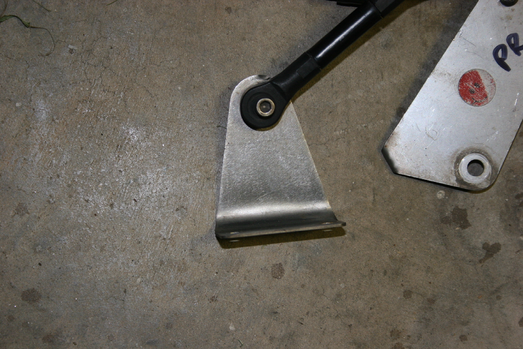
Front Arm Brackets |
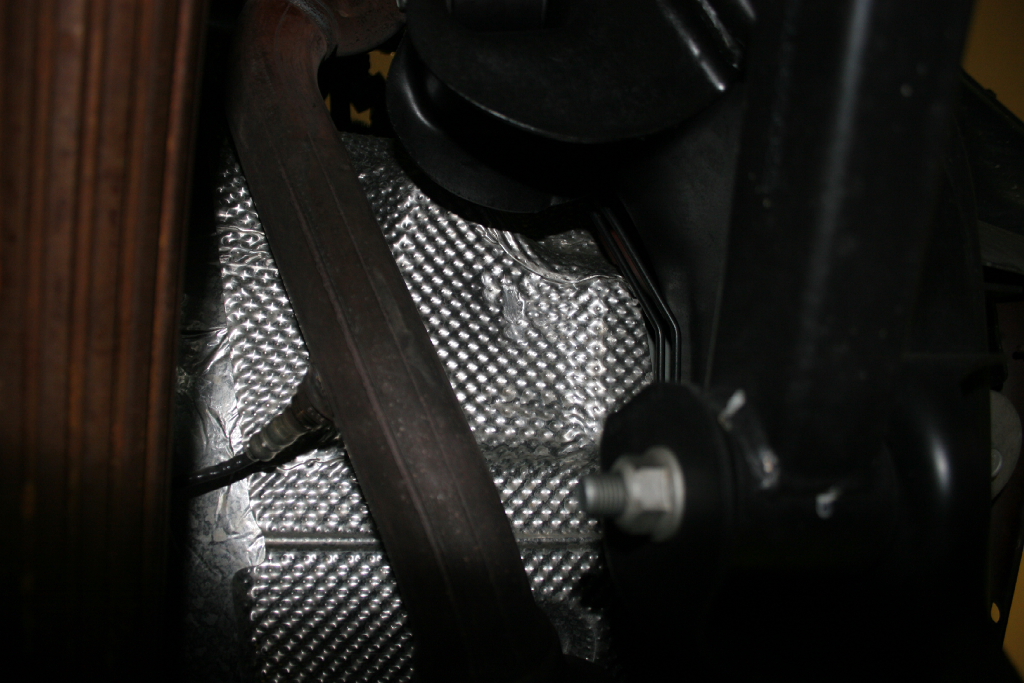
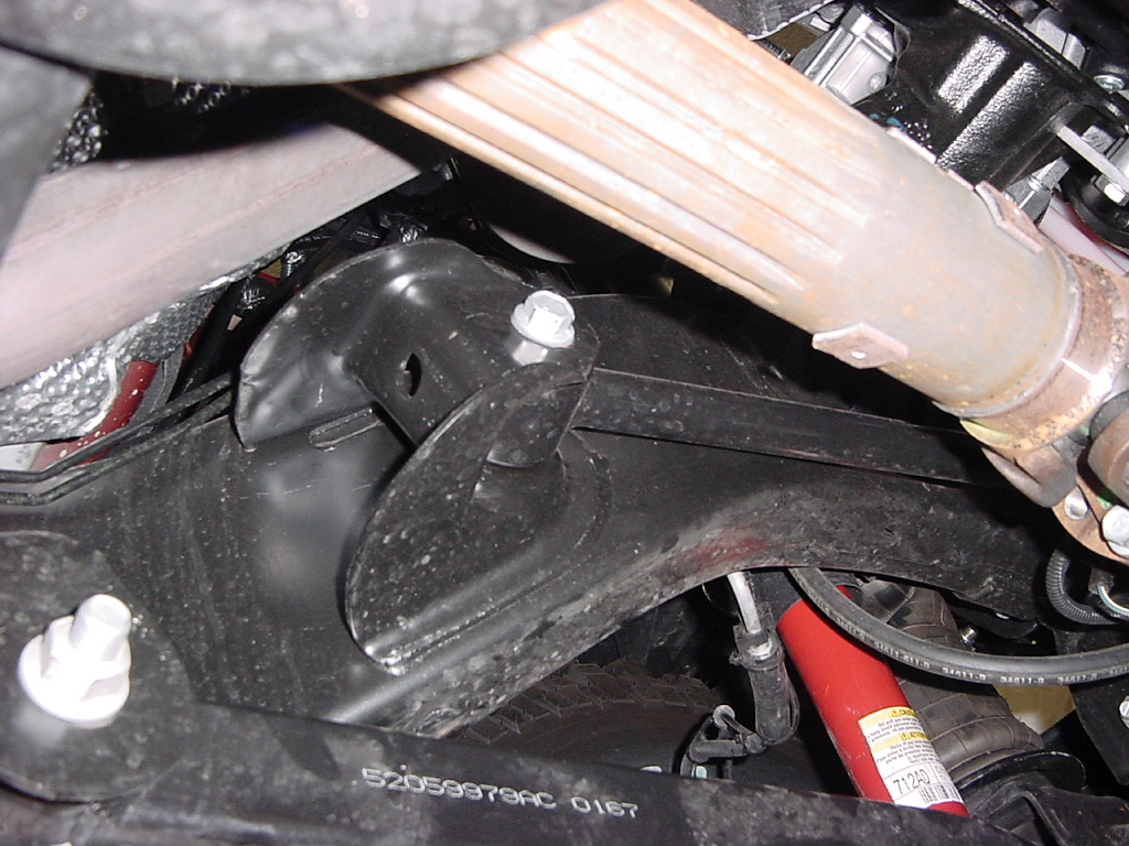
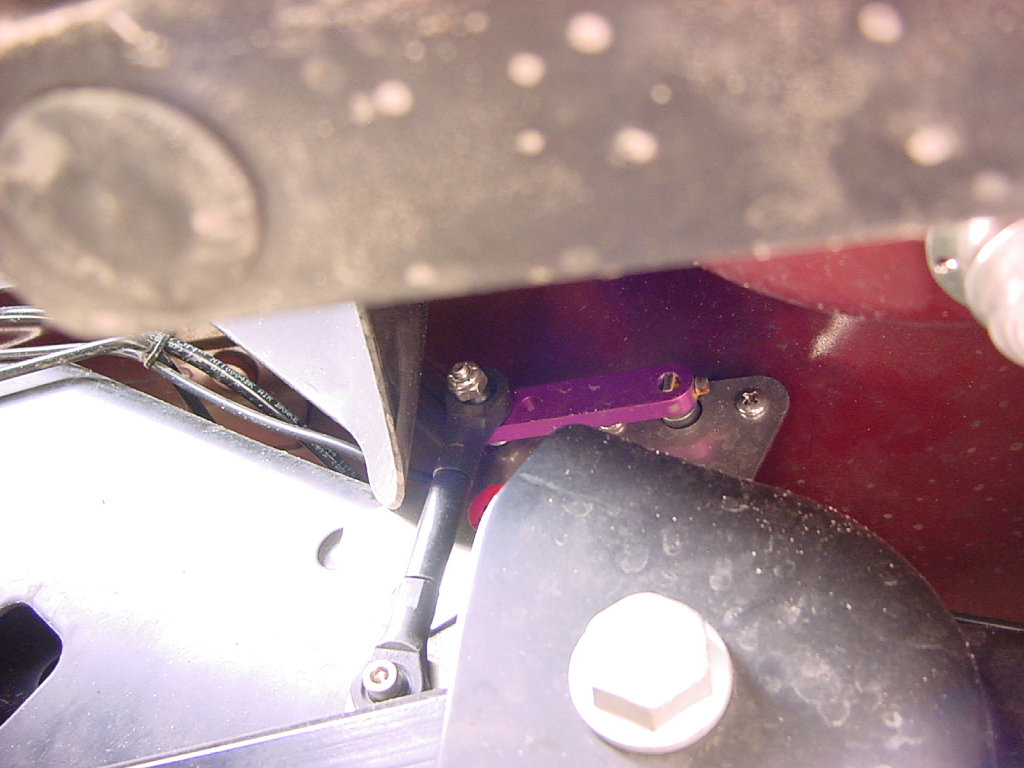
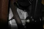
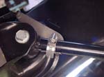
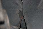
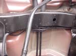
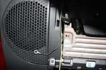
Dimple the heat shield on the drivers above and behind the upper control arm frame bracket. This will ensure enough clearance on the sensor arm for it to move freely. |
 |
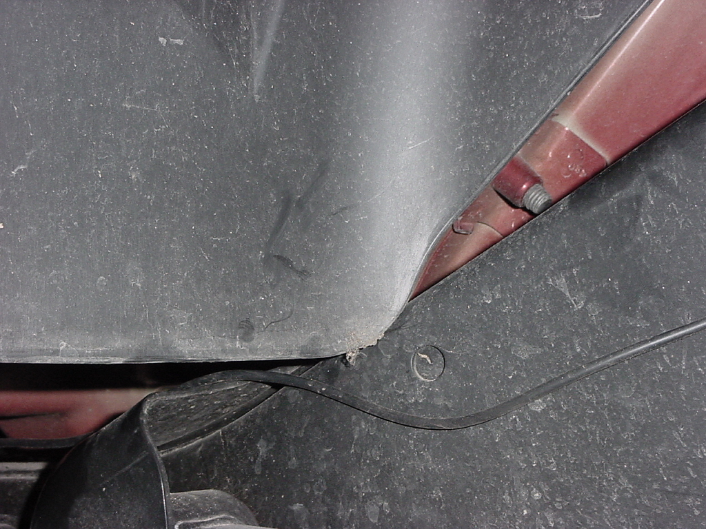
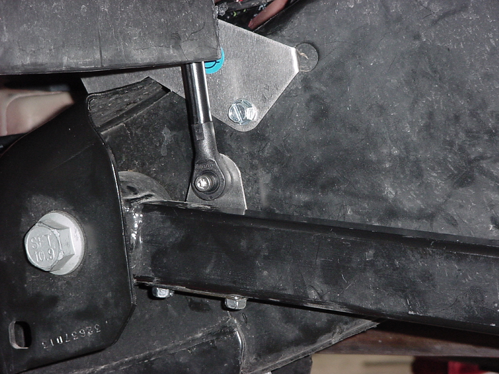
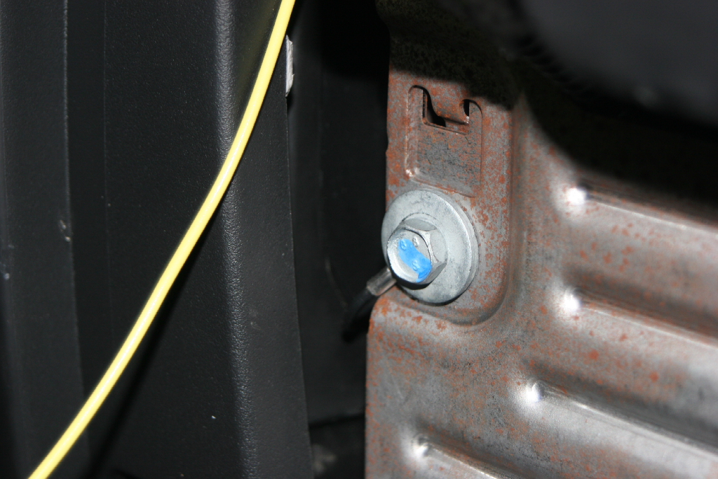
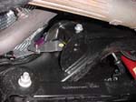
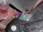
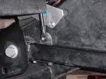
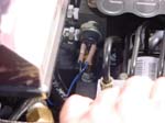
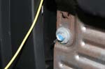
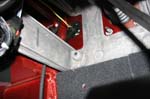
Remove the nut from the bolt in the front upper control arm frame bracket. You will not need to pull this bolt out, just enough to slide the sensor bracket between the nut and the bracket. 18mm socket for the drivers side, and an 18mm combo wrench for the passenger side. |
|
Slide the bracket between the frame and the bracket. Insert the bolt through the bracket and reinstall the nut. You need to make certain that this bracket stays lined up with the arm, otherwise you can bind the rotary arm. |
 |
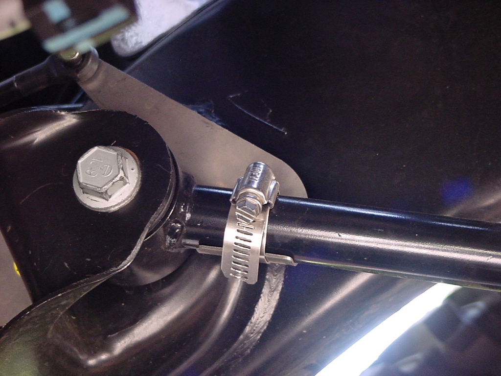
Open up one of the hose clamps, and slide it through the slot in the arm bracket |
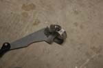 |
| Clamp the arm bracket onto the upper control arm. The bracket will rest against the head of the control arm, and sit on the outside. |
 |
Attach the rotary arm to the arm bracket with the supplied allen head bolt. The nut will be towards the outside. You will need a 5/32" allen wrench and a 3/8" Socket. |
|
| |
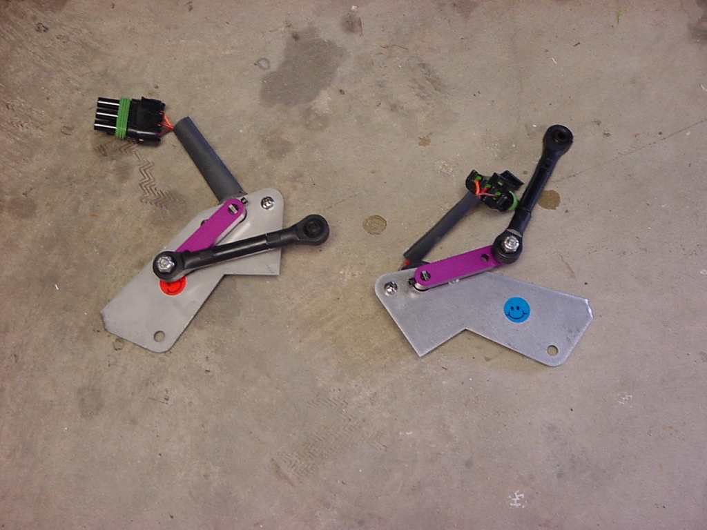
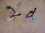
| Install the rear height sensors: (the colored smilies in these pictures were reversed in the first couple kits, this has been corrected) |
 |
 |
 |
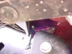
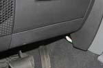
| You may wish to cut the leading edge of the wheel well liner. The arm is close, and I have had no issues with the uncut side. |
|
 |
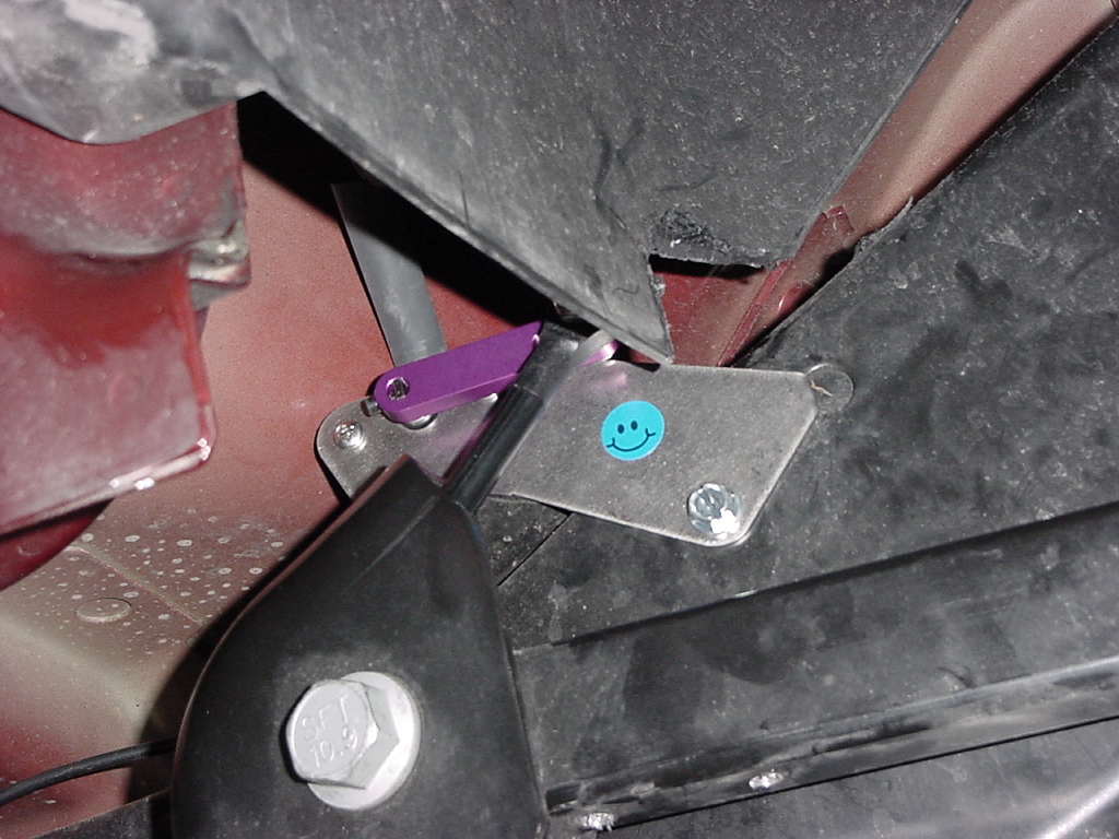
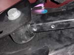
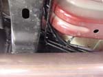
| Place the sensor on top of the upper control arm frame bracket, the sensor will index with the hole on the frame. Red on drivers side, blue on passenger side. |
 |
Drill and tap the frame with a 1/4-20 tap to mount the sensor in location. Take your time with this step, the frame is very strong, and you do not want to snap off a drill bit, or a tap in the hole. ORO does provide self taping bolts, but I strongly recommend, buying the Tap.
|
 |
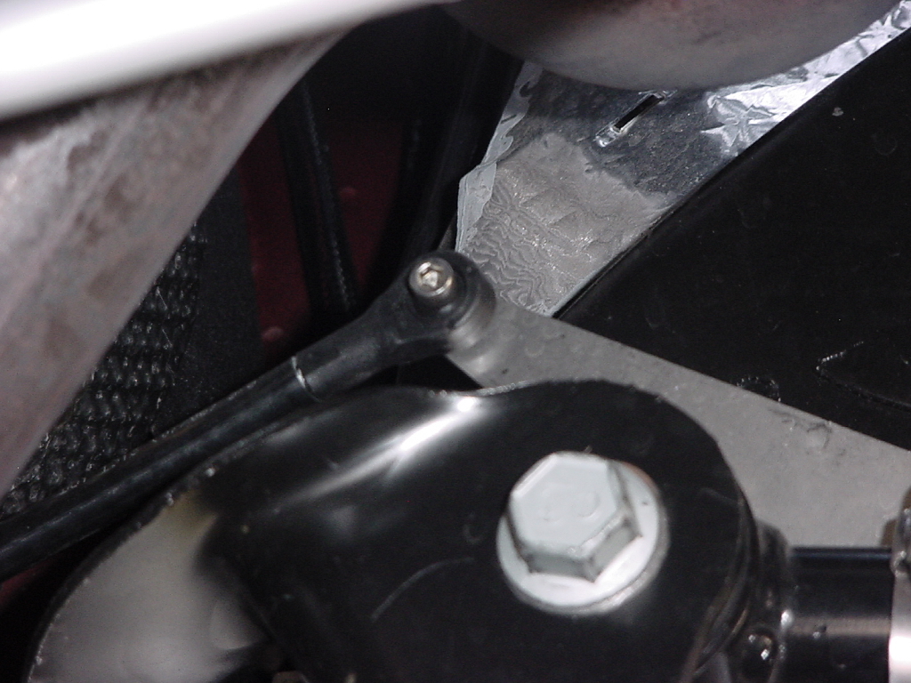
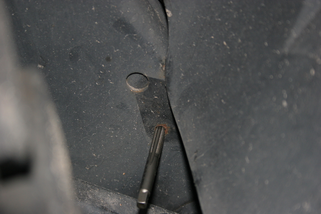
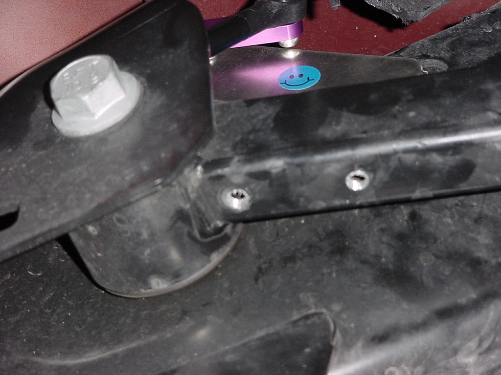
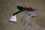
| Place the L shaped bracket on the underside of the upper control arm. The triangular section with the single hole should be up and towards the frame. Rest one end against the head of the arm, mark, drill and tap the two holes. |
 |
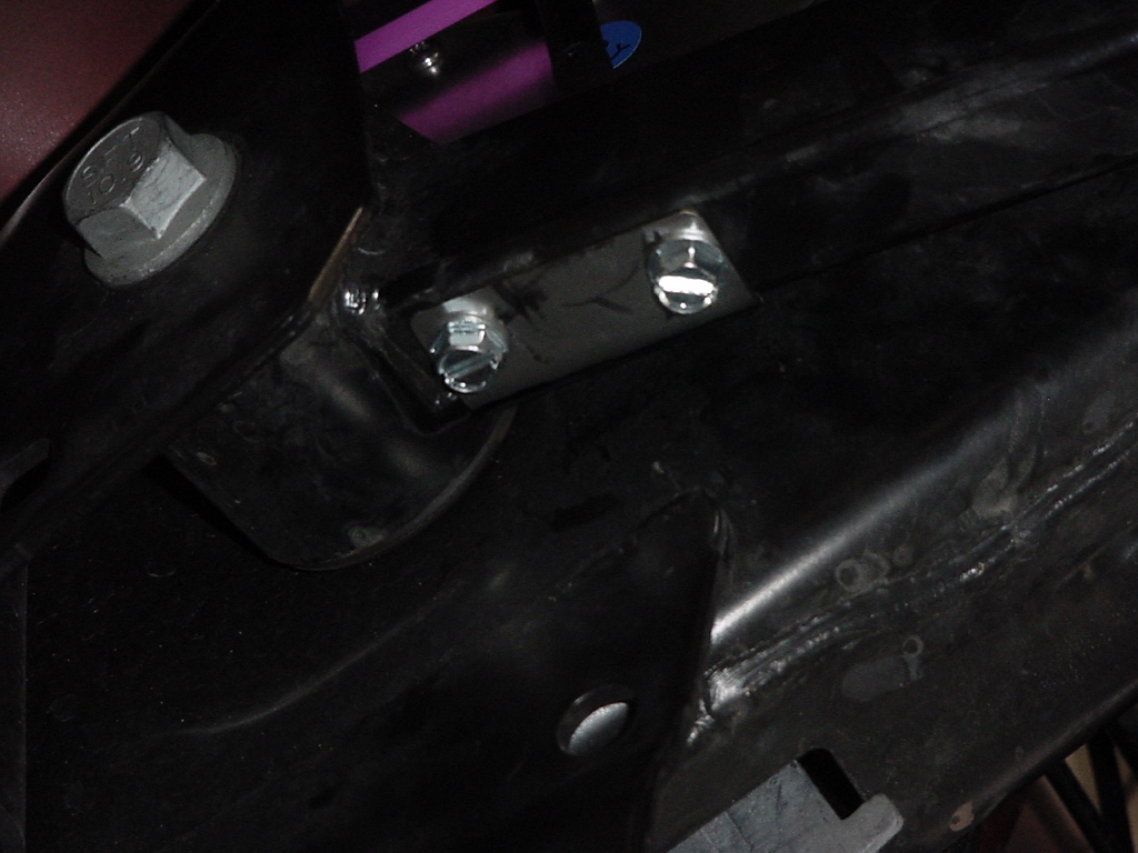
| Bolt the arm bracket in place with the supplied self tapping bolts. |
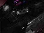 |
| Connect the rotary arm to the upper control arm bracket with the supplied allen head bolt and nut. You will need a 5/32" allen wrench and a 3/8" combo wrench. |
 |
| |
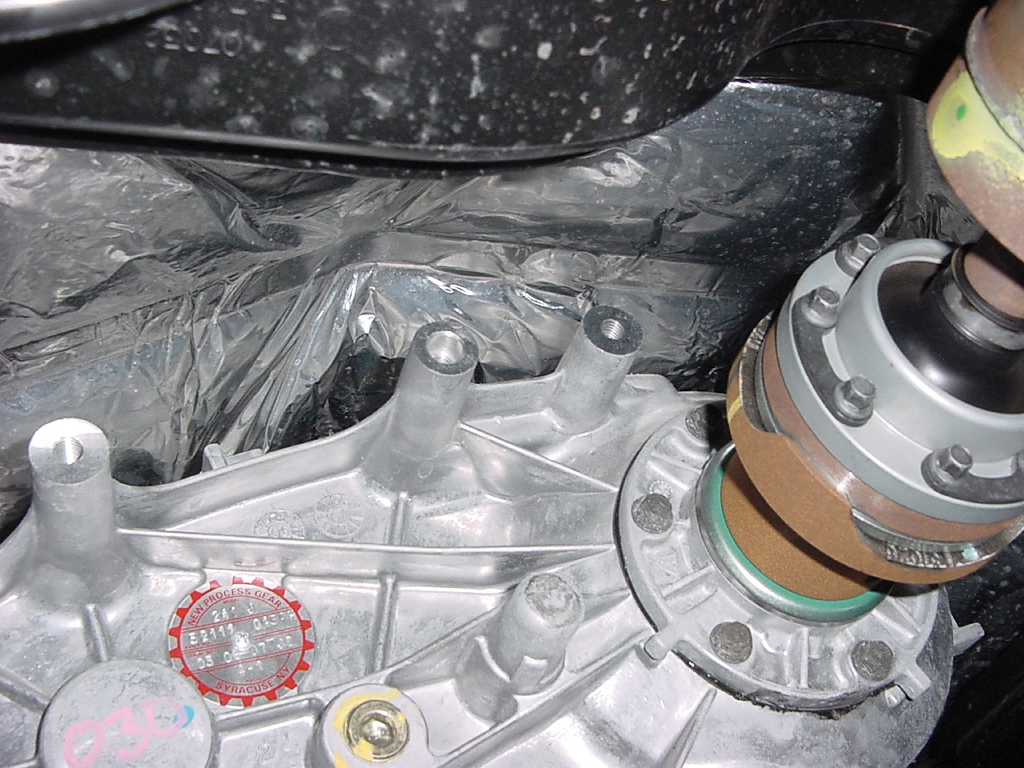
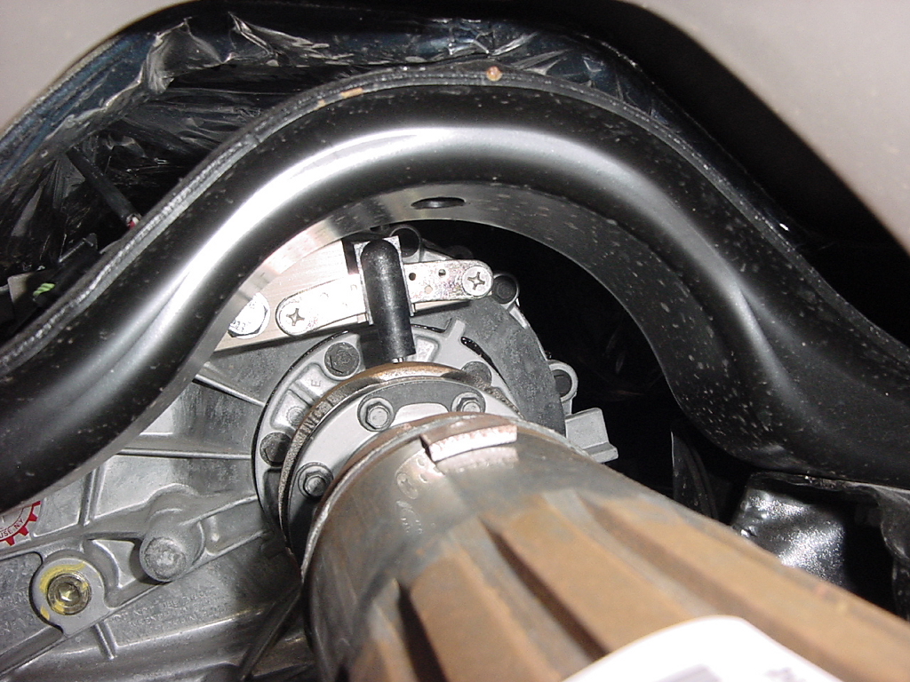
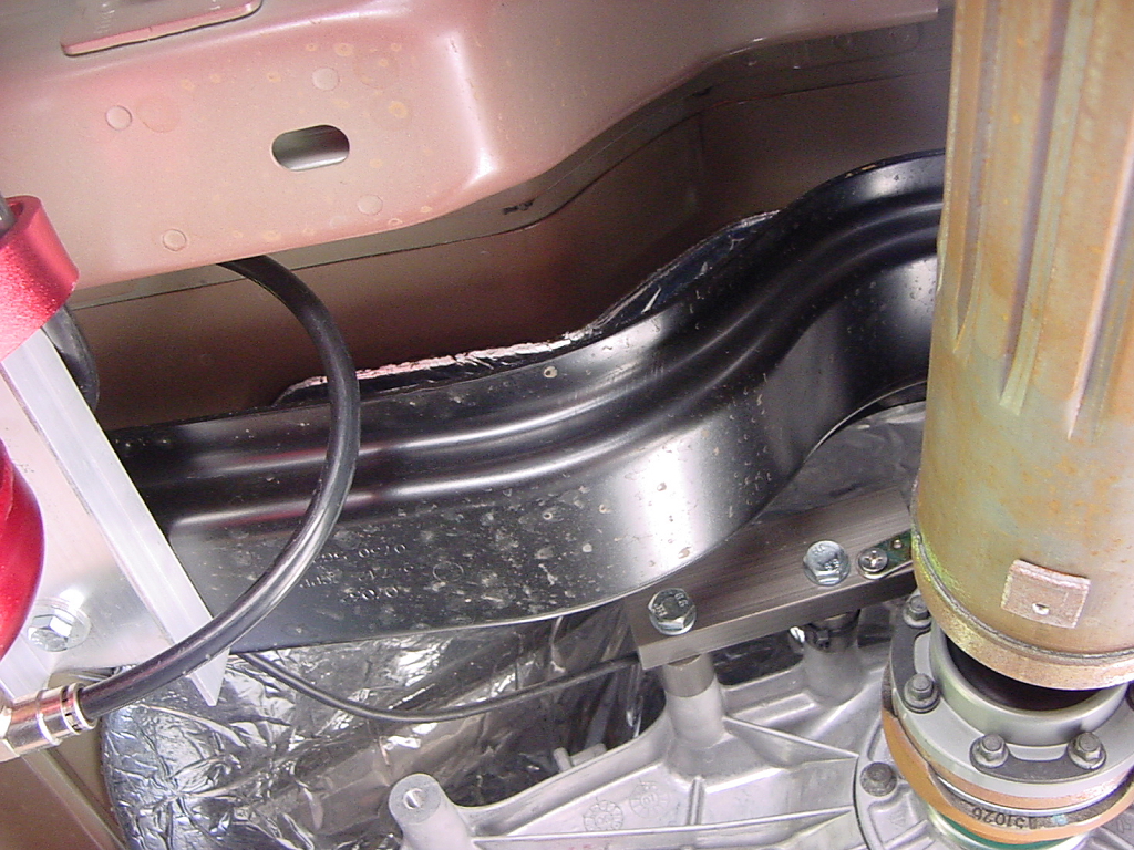
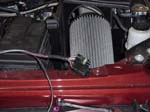
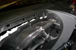
| Install the speed sensor: |
 |
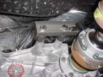
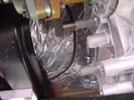
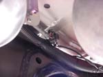
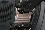
| The speed sensor bolts to the two upper boss's on the transfer case. There are two different length bolts provided. The outer boss may be pilot drilled and then tapped for a bolt, this is the boss that will use the longer bolt. If you use the shorter bolt, you will strip out the threads in the boss when you tighten down the speed sensor. |
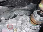 |
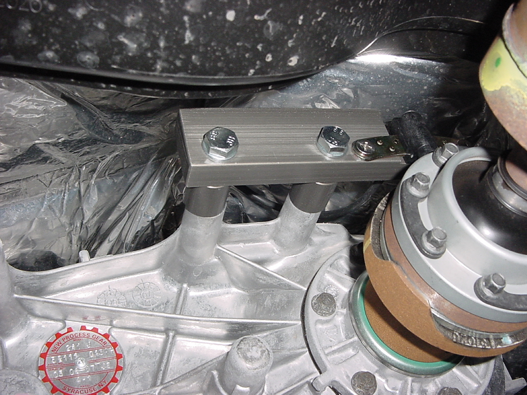
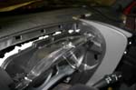
| Install the bolts through the speed sensor. |
 |
| Adjust the speed sensor pickup to be .025" above the drive shaft. This is the thickness of a soda carton. There should be a mysterious piece of cardboard in your kit. Tighten down the speed sensor bracket. |
 |
| |
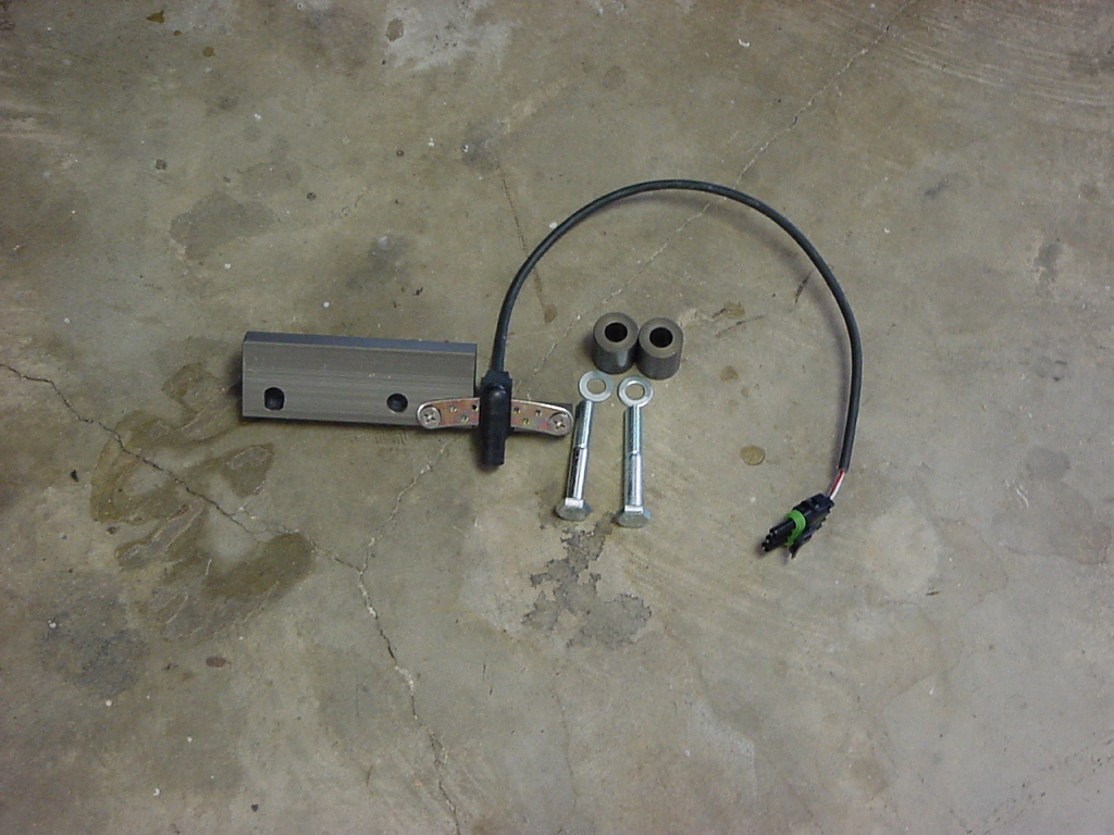
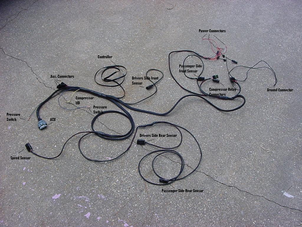
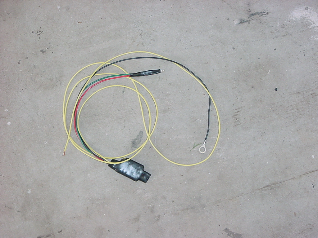
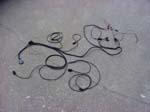
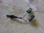
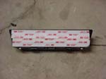
| Install the wiring harness: |
| Lay the harness out on the floor to get a general idea on how it will route. |
 |
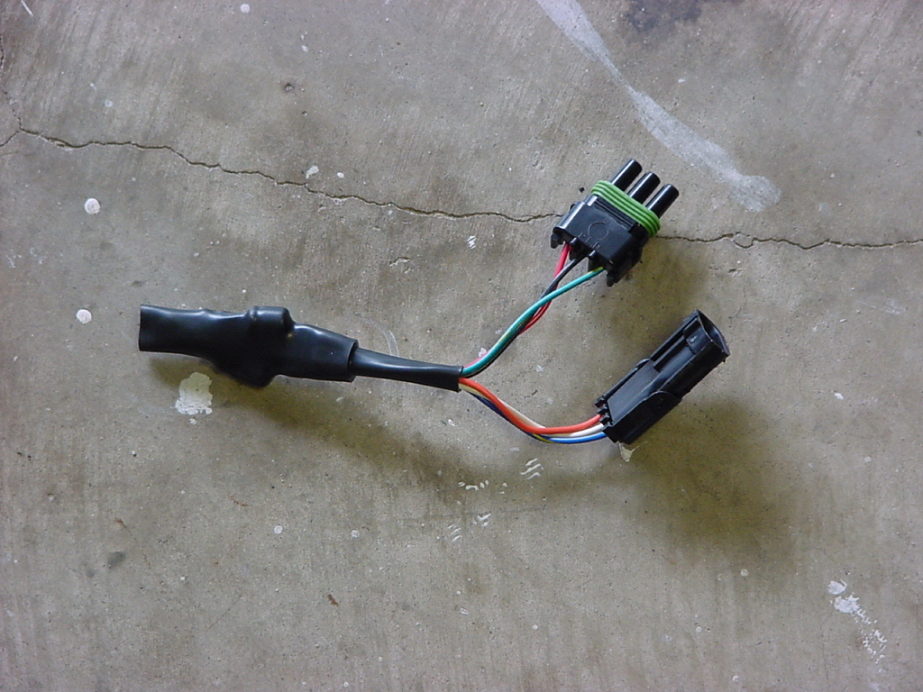
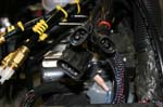
| Connect the Compressor Relay Override to the harness. Doing this early saves some possible confusion as to the connectors on the passenger side. |
 |
 |
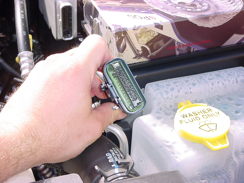
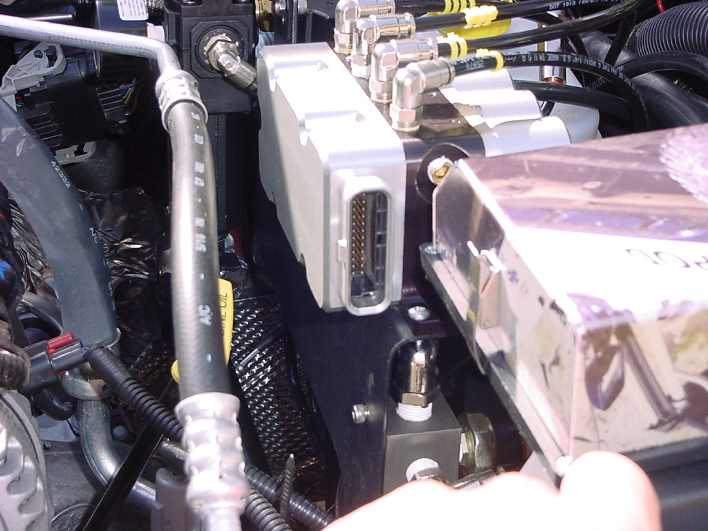
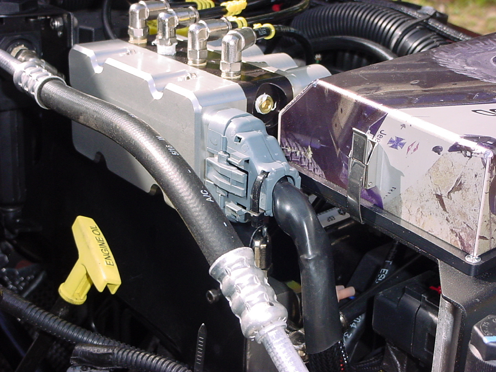
| Plug the ACU connector into the ACU |
|
|
|
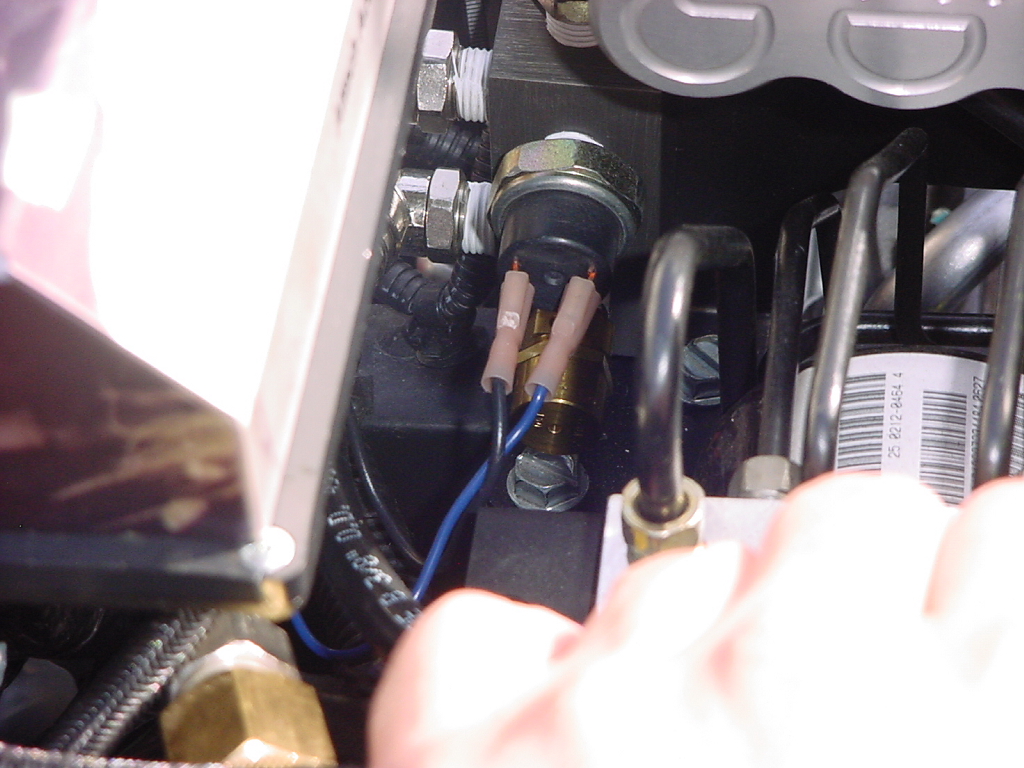
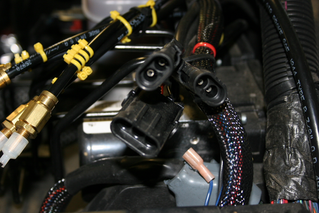
| Plug the two pressure switch connectors into the pressure switch |
 |
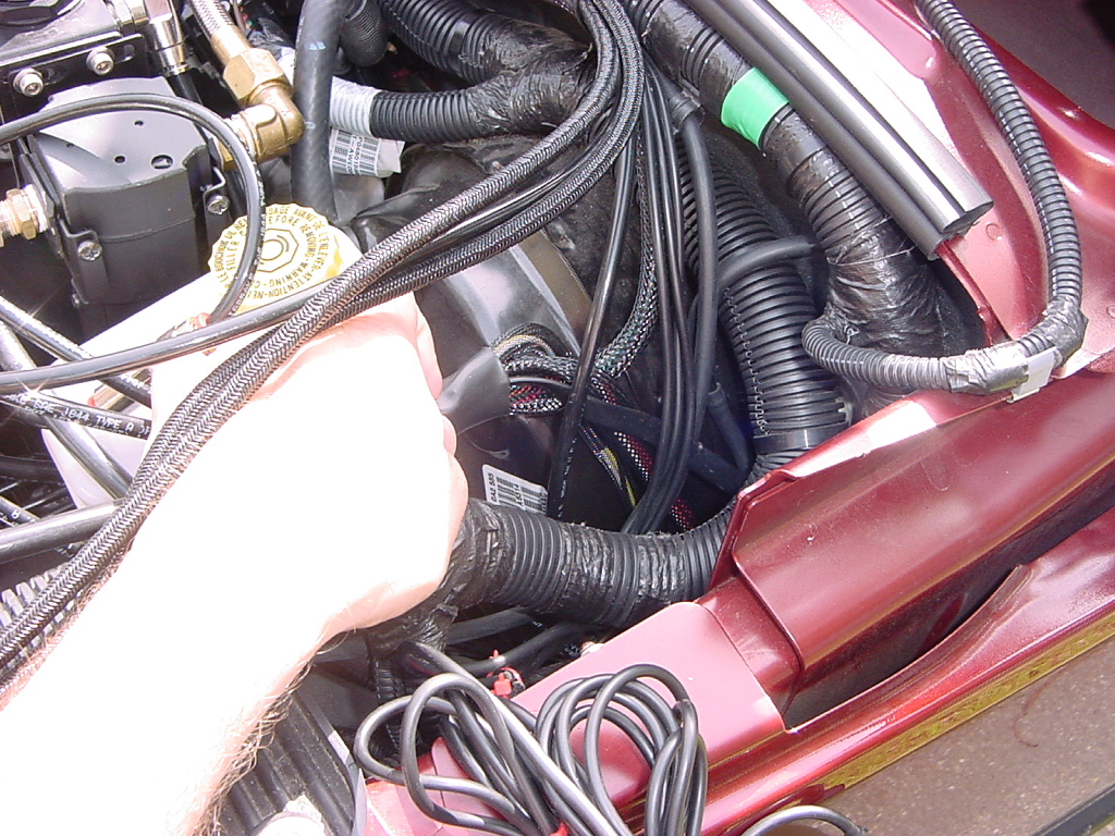
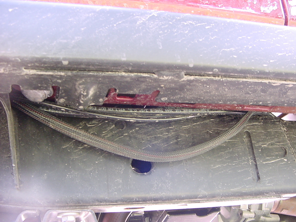
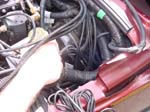
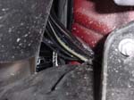
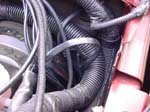
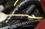
| Route the drivers side front, drivers rear, passenger rear, and speed sensor line down along the outer edge of the fender next to the fire wall, this will come out behind the wheel well liner. |
 |
 |
| Connect the driver side front sensor. |
 |
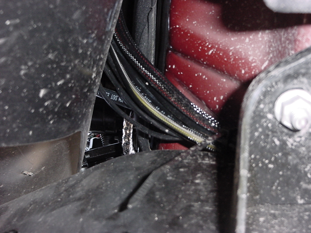
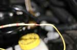
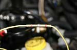
| Route the sensor lines along the frame |
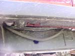 |
| Run the speed sensor line over the cross members to the speed sensor. Connect the speed sensor line |
 |
 |
| Run the rear driver and passenger side sensor lines |
 |
 |
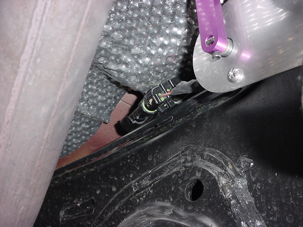
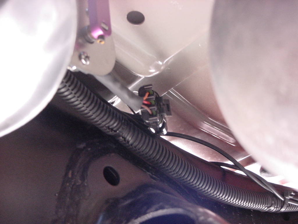
| Connect the driver and passenger side rear sensors. |
|
|
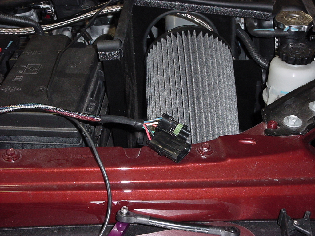
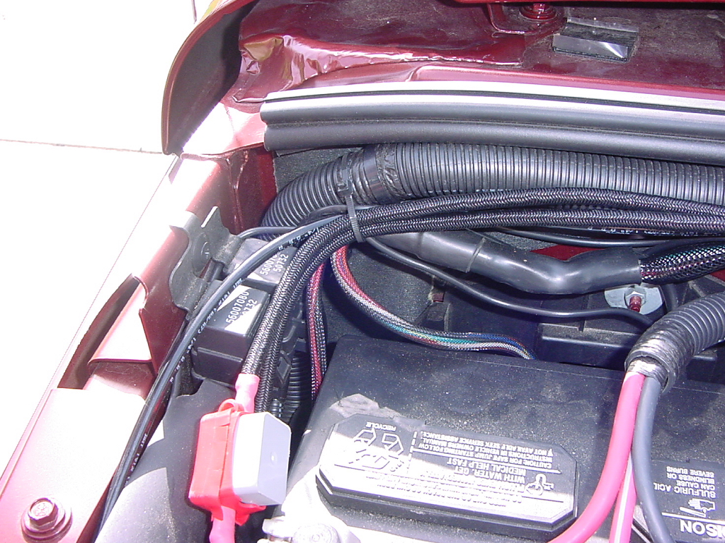
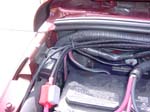
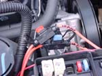
| Route the power, compressor relay override, and passenger front sensor lines over to the battery side. |
 |
| Route the passenger side front sensor line down along the outer edge of the fender next to the fire wall, this will come out behind the wheel well liner. |
 |
 |
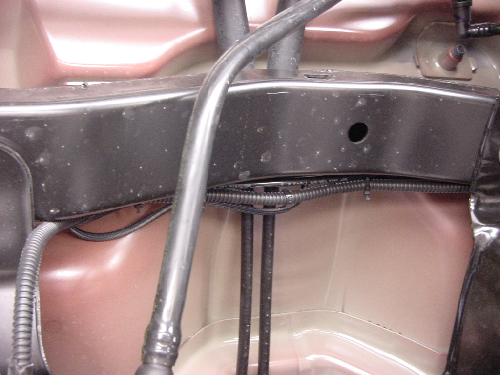
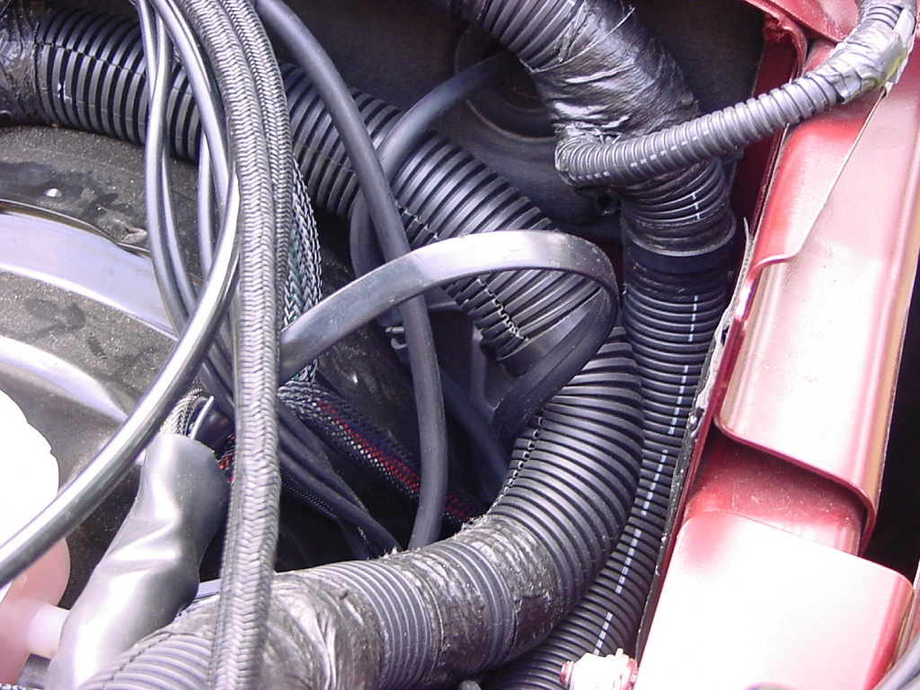
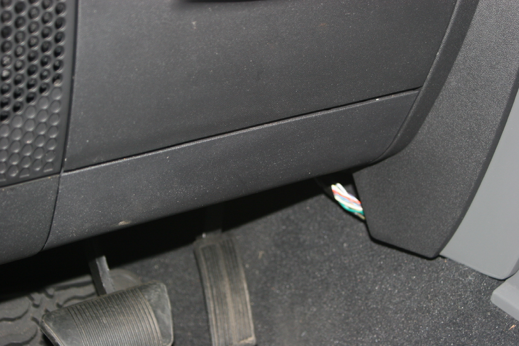
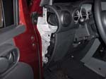
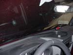
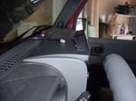
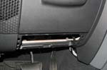
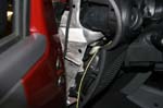
| Route the controller line through the firewall on the drivers side. You can either use the clutch hole (if you have an auto) or the grommet above it where the rear washer fluid line goes through if you have a hard top. |
 |
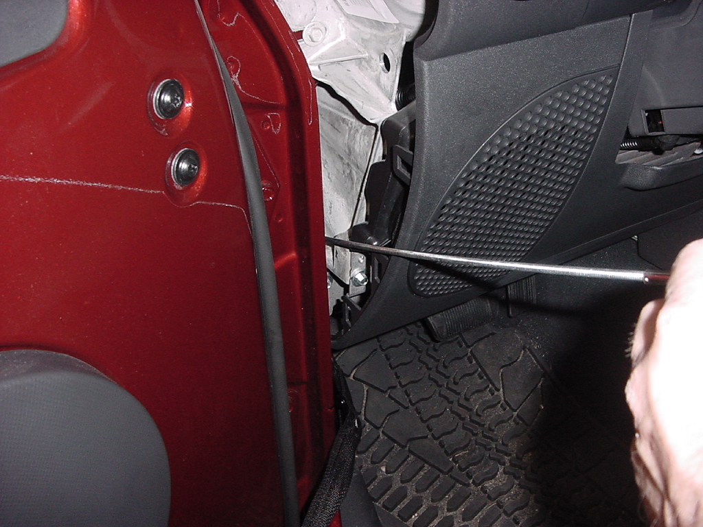
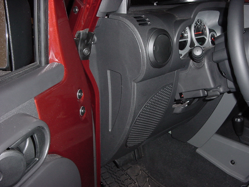
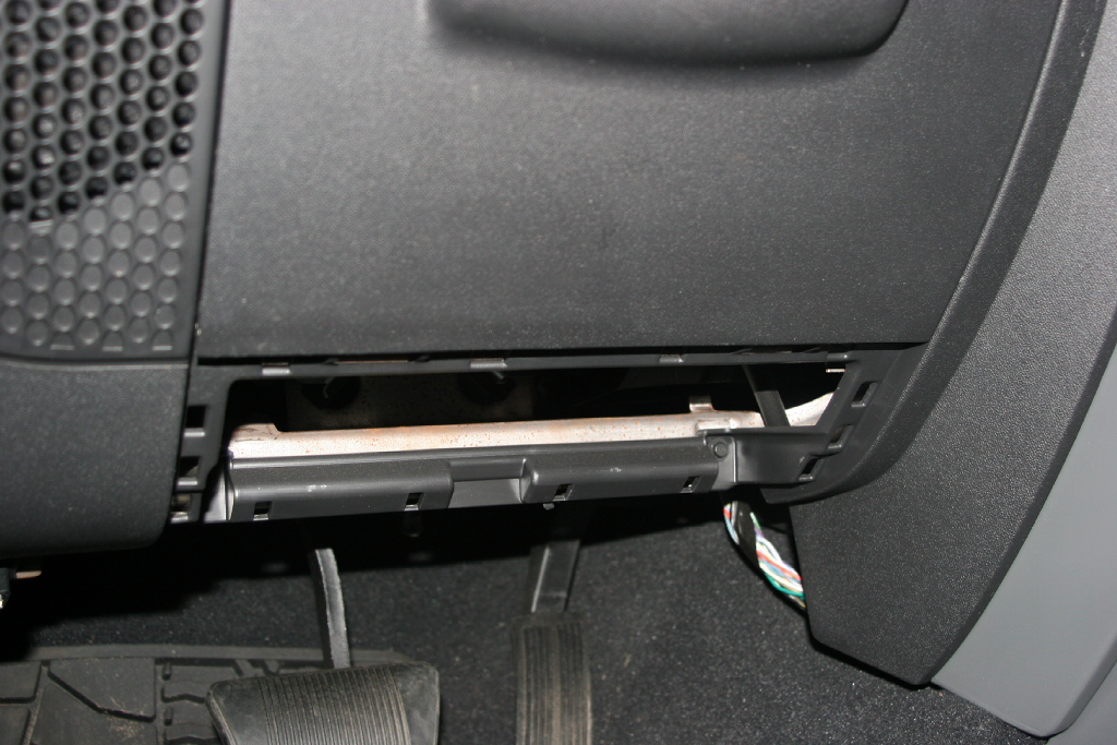
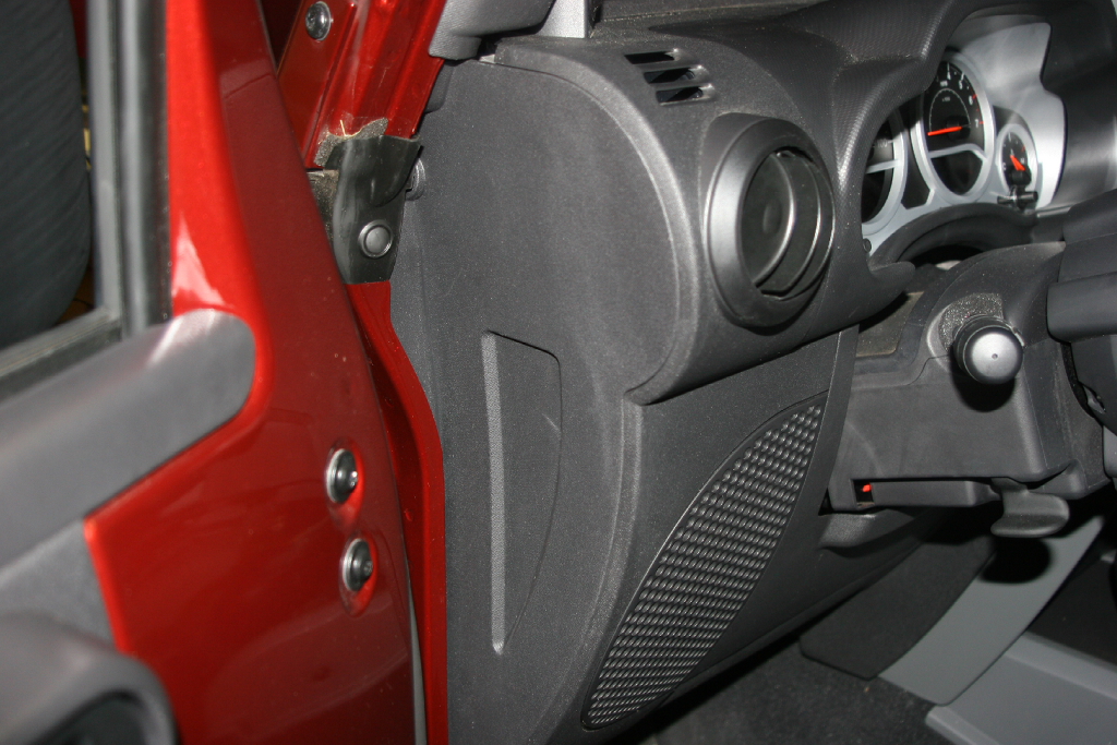
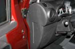
| Remove the side panel from the dash, it just pry's out. You might need a flat tip screwdriver to get underneath it. |
 |
 |
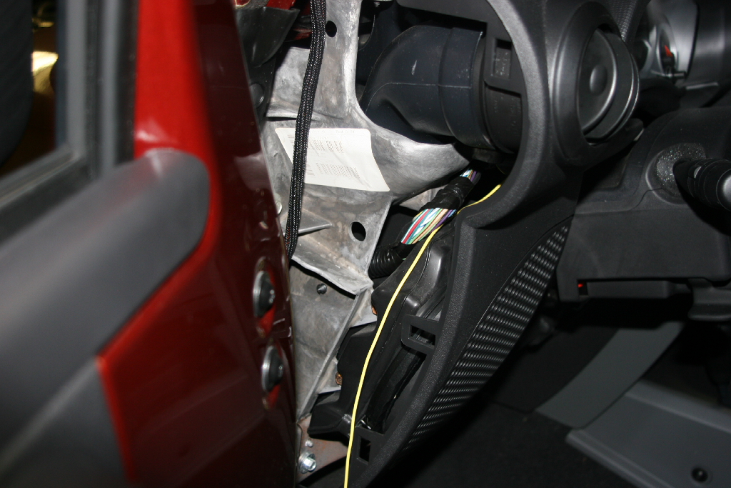
| I used a mechanical fingers to slip between the dash frame and the body to retrieve the wire from the firewall. |
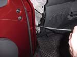 |
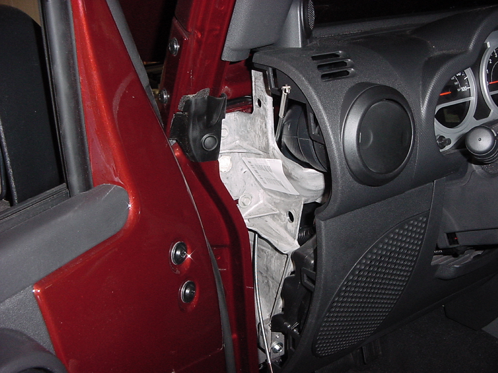
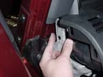
| Once you have the wire pulled out, you can hook onto it with the mechanical fingers and run it up inside the dash frame. I found going up was much easier than trying to feed the fingers back down to latch on to the wire. |
 |
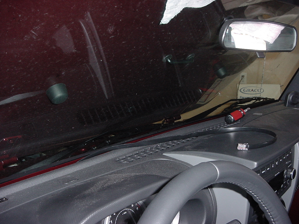
| Slip the wire behind the rest of the dash and up against the windshield. |
 |
| Just run the wire back along the edge of the dash. |
 |
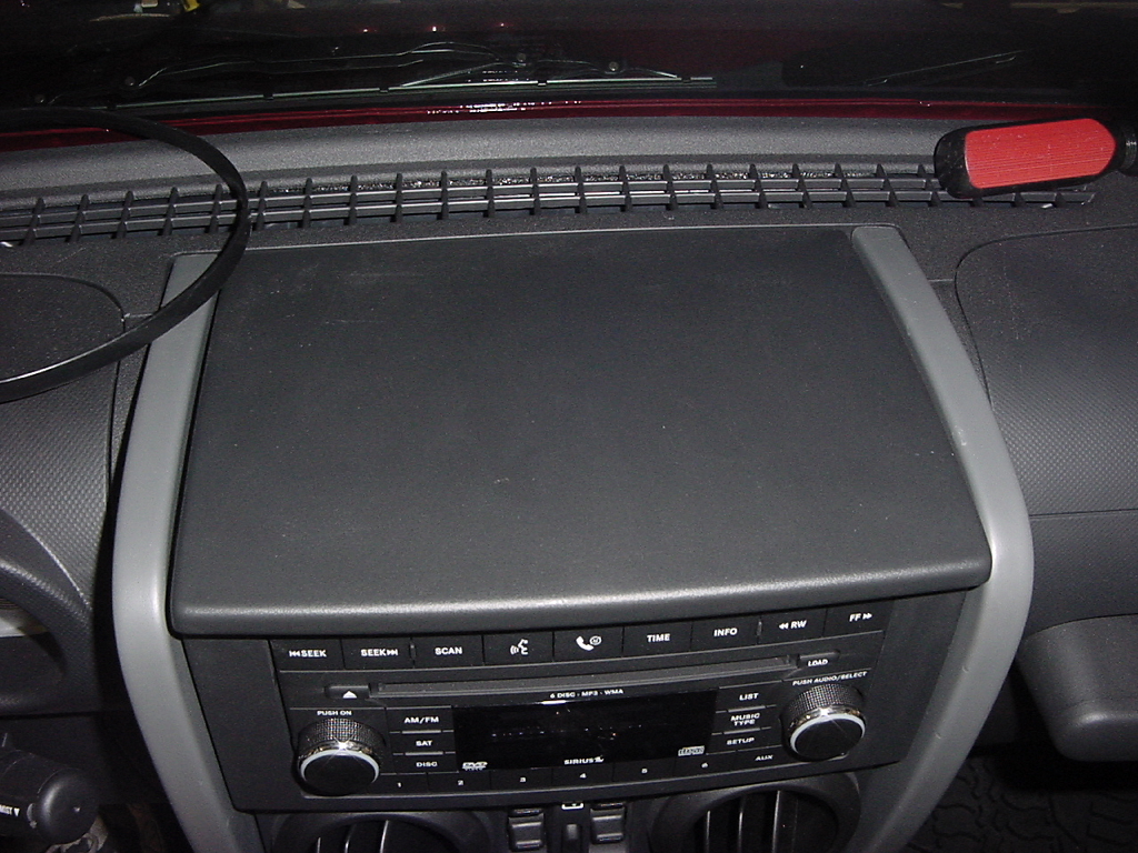
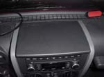
| Clean off the top of the center dash. |
 |
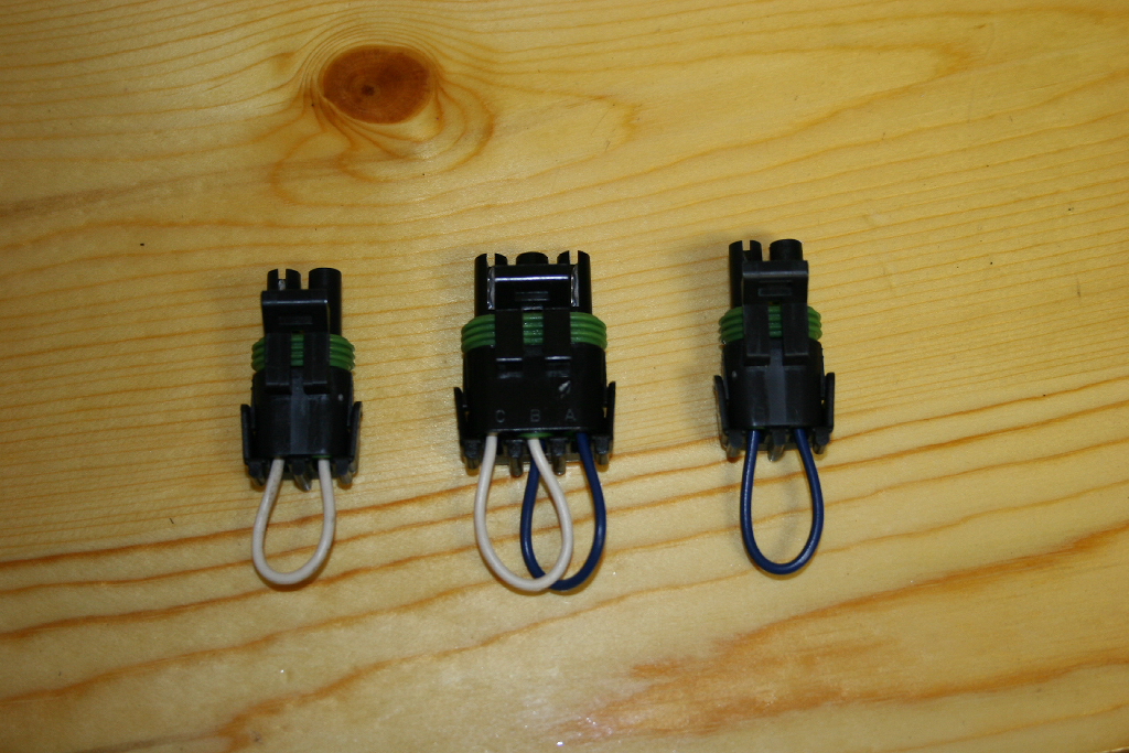
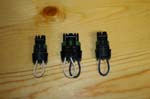
| Install the 3 harness termination plugs in the ends of the harness on the driver side. |
 |
 |
| |
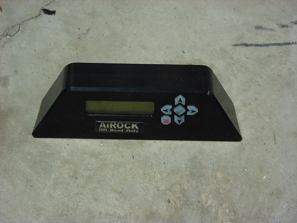
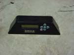
| Mounting the AiROCK Controller: |
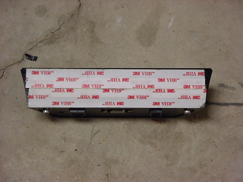
| Remove the backing from the double sided tape on the bottom of the AiROCK controller. |
 |
 |
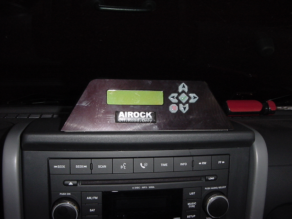
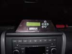
| Press the AiROCK controller firmly down on to the dash. I normally position them towards the front so that they are within better reach. Mounting them above the steering wheel can pose problems with seeing the display and operating the controls. |
 |
 |
| Don't forget to reinstall the side panel. It's actually a little harder to get in than out. |
 |
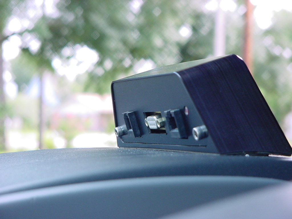
| Plug in the controller wire to the back of the AiROCK Controller. |
|
| |
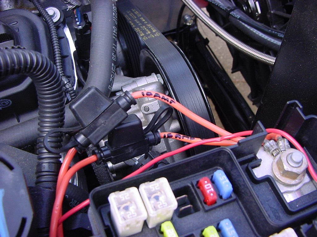
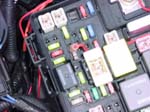
| Connecting to Power: |
| Mark the wires, and remove the fuses from each holder. |
|
 |
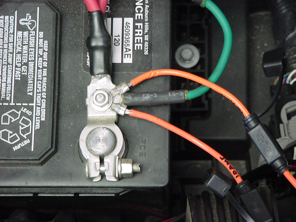
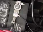
| Attach the power wires to the power post of the fuse box, or the positive terminal of the battery. You will need a 13mm combo wrench for the power post or a 10mm combo wrench for the battery terminal |
|
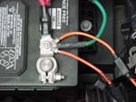 |
| Connect the ground wire to the negative battery terminal. You will need a 10mm combo wrench |
 |
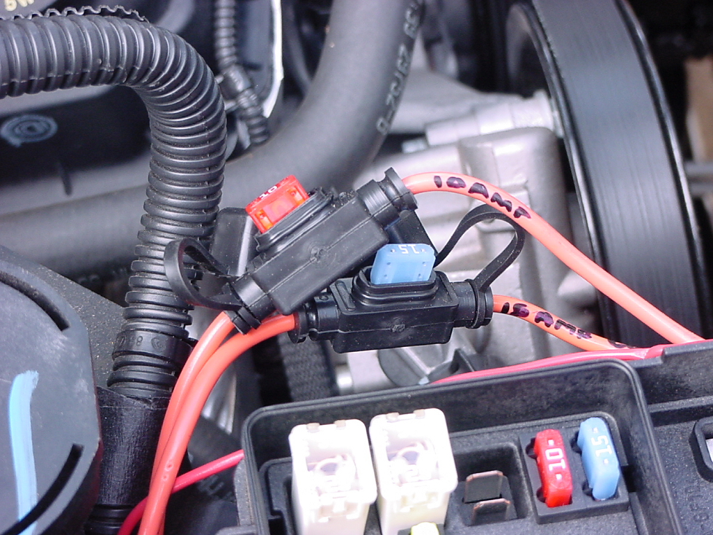
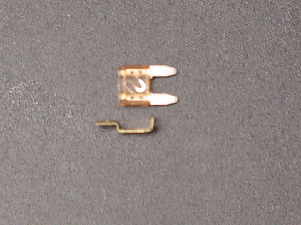
| Carefully remove the taped on fuse tap. |
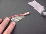 |
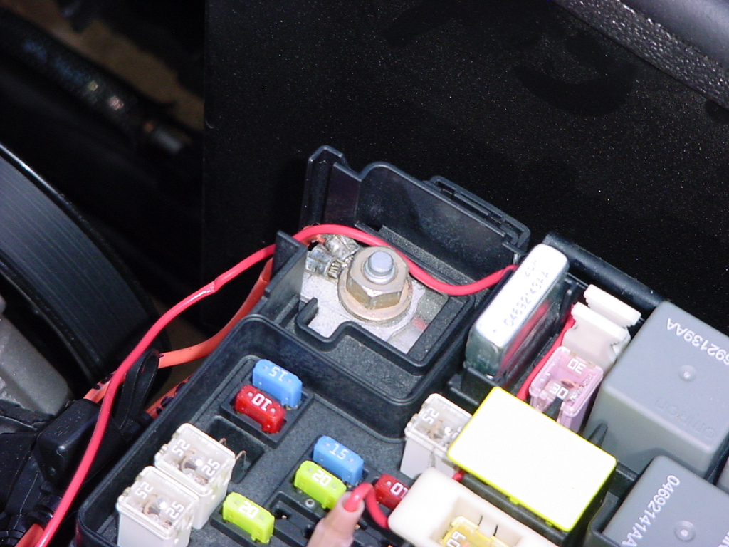
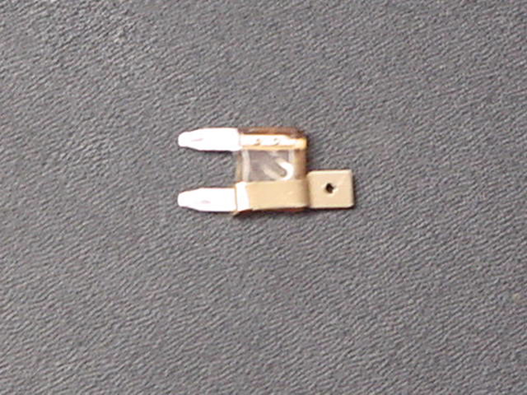
| Install the fuse tap on a spare fuse. The tap will go on the load side of the fuse when installed. |
 |
 |
| Connect the fuse and fuse tap in to a switched circuit in the fuse box. This will deenergize the compressor clutch when the engine is shut off saving a load on your battery. I used |
 |
| WARNING: DO NOT REINSTALL THE FUSES UNTIL ASSEMBLY IS COMPLETE ON THE AiROCK. |
| |
| Installation compressor run indicator LED: |
| Off Road Only included an indicator to show when the compressor was running. One of the leading causes of compressor failure is excessive run time. Normally if you blow a line it is quickly noticeable with a bag going down, or complete air loss of the system, but if you have a leak that causes the compressor to stay running you might not hear it driving down the freeway. |
|
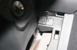
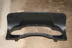
| Remove the lower knee panel from the dash. You will need to pry it out with a trim tool, or very carefully with a small flat bladed screwdriver. |
 |
 |
| Remove the upper trip panel from the dash. You will need to pry out the top two edges of the panel. The bottom is hinged into the dash and comes off when you swing the panel down. |
 |
 |
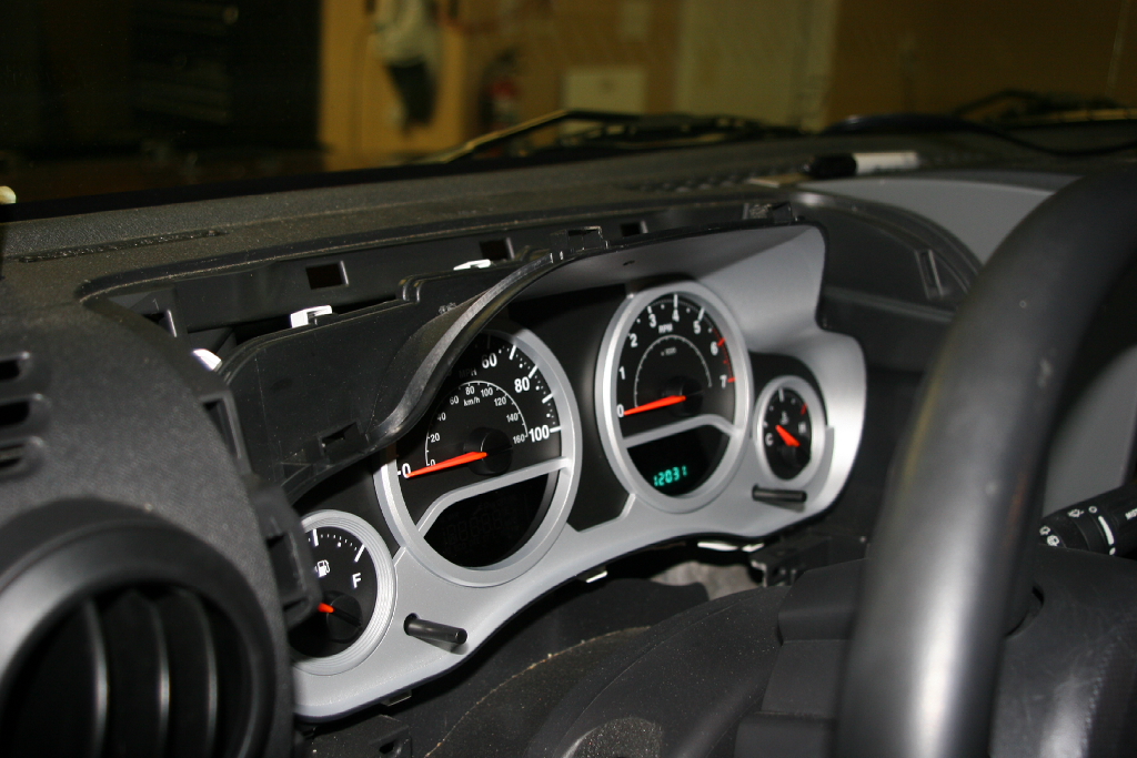
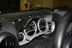
| Remove the two screws, one on either side of the instrument panel surround. This requires a 7mm socket. Once you have the screws removed the surround pulls forward and off. You may need to tilt the steering wheel down. |
 |
 |
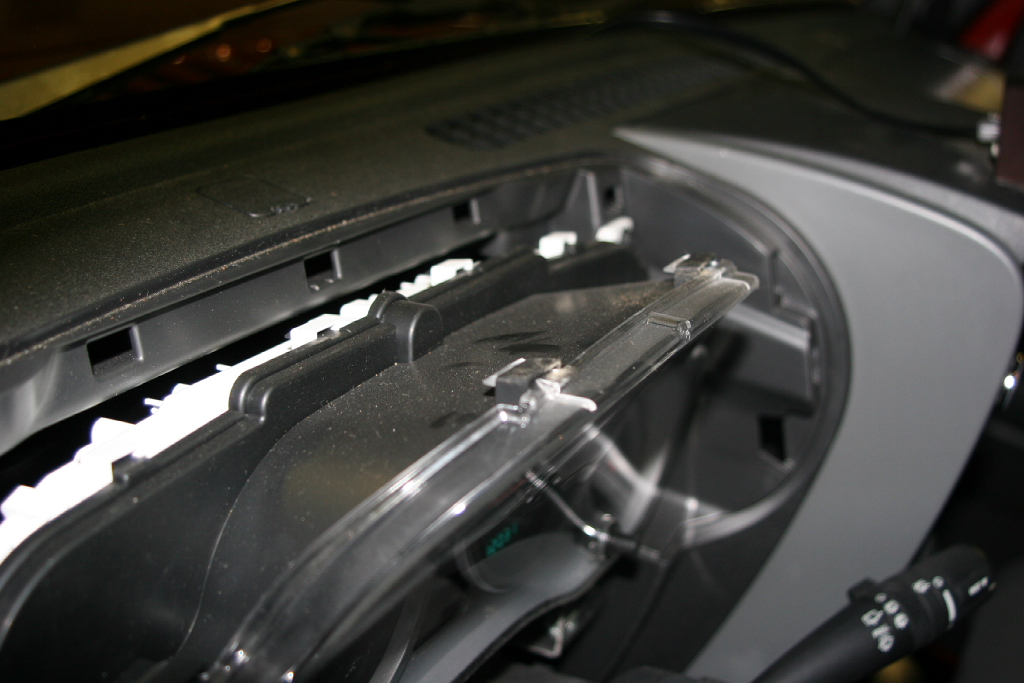
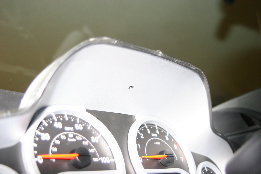
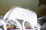
| Make a mark in the center top of the instrument panel caseing. I used the mold mark on the center of the plastic lens and made a mark about three quarters of the way back on the top. |
 |
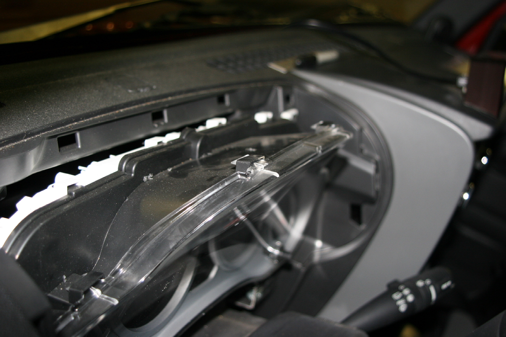
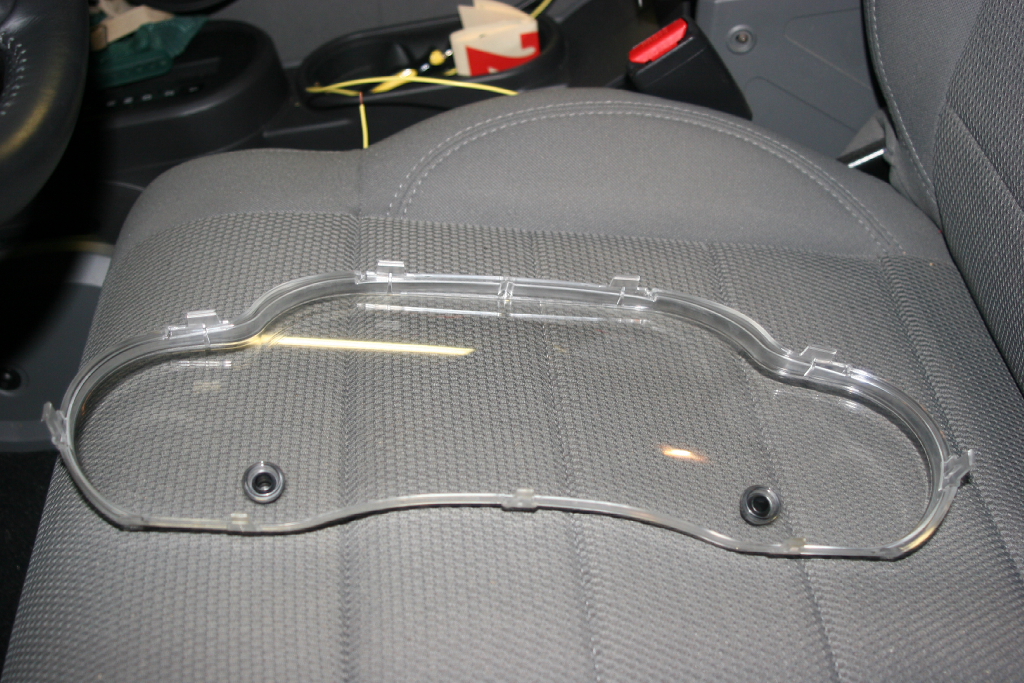
| Remove the clear plastic lens form the instrument cluster. Depress the two locking tabs on the top and push them out. The lens will pull off. |
 |
 |
 |
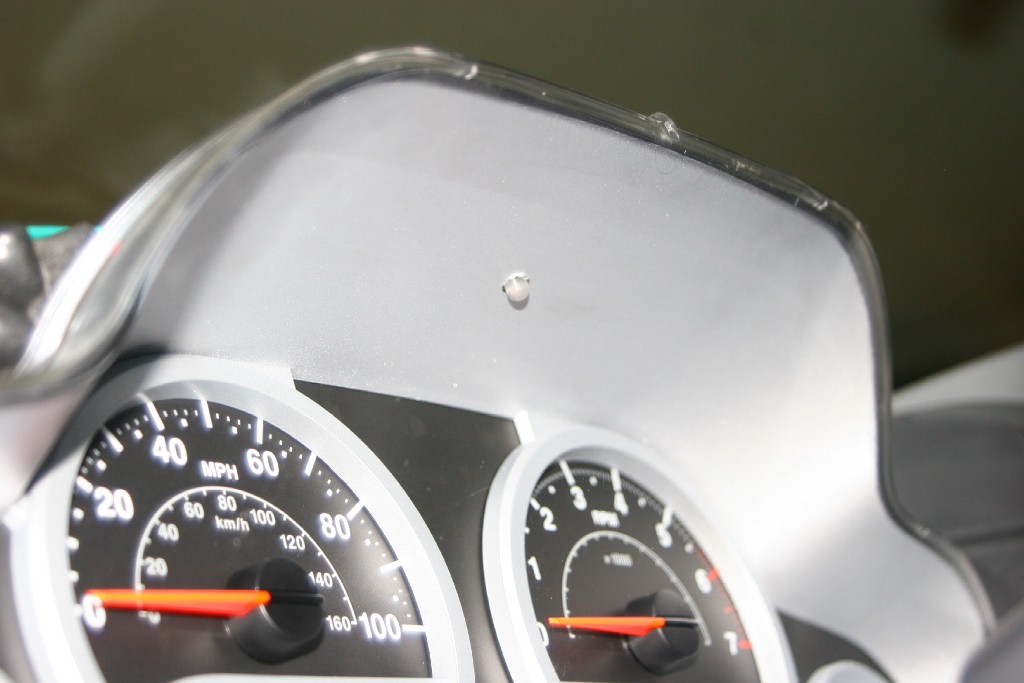
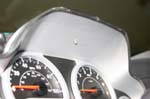
Drill a 3/16" hole in the top of the instrument casing and remove any plastic burrs that remain.
Note: Check the size of our LED before you drill, and drill using a drill bit one size smaller to begin with. This will give you a snug fit. |
 |
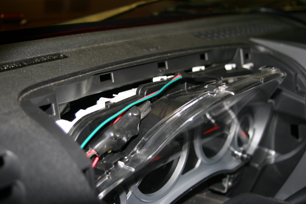
| Insert the LED through the hole, and reinstall the plastic lens. |
 |
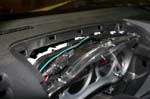
| Tuck the circuit board along the top of the instrument cluster and route the wires down along the side of the instrument cluster. Once you have the wires tucked away, reinstall the instrument cluster surround. |
 |
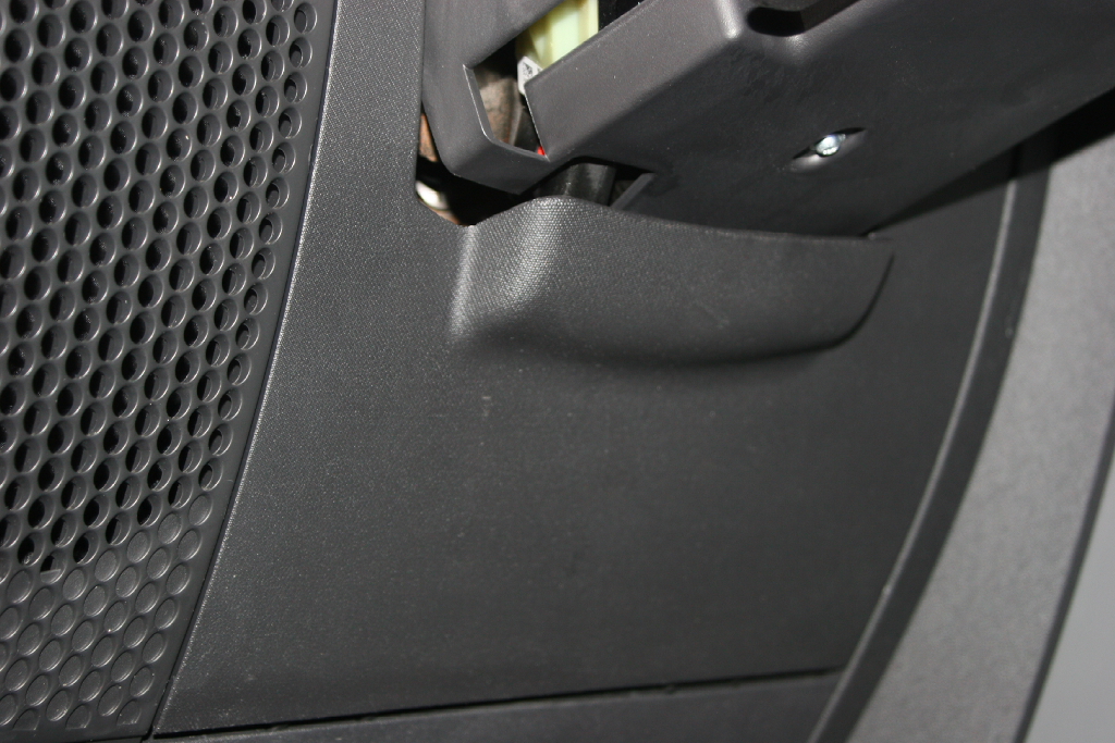
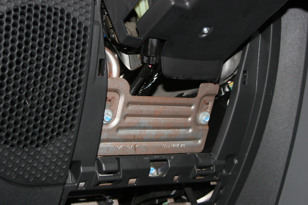
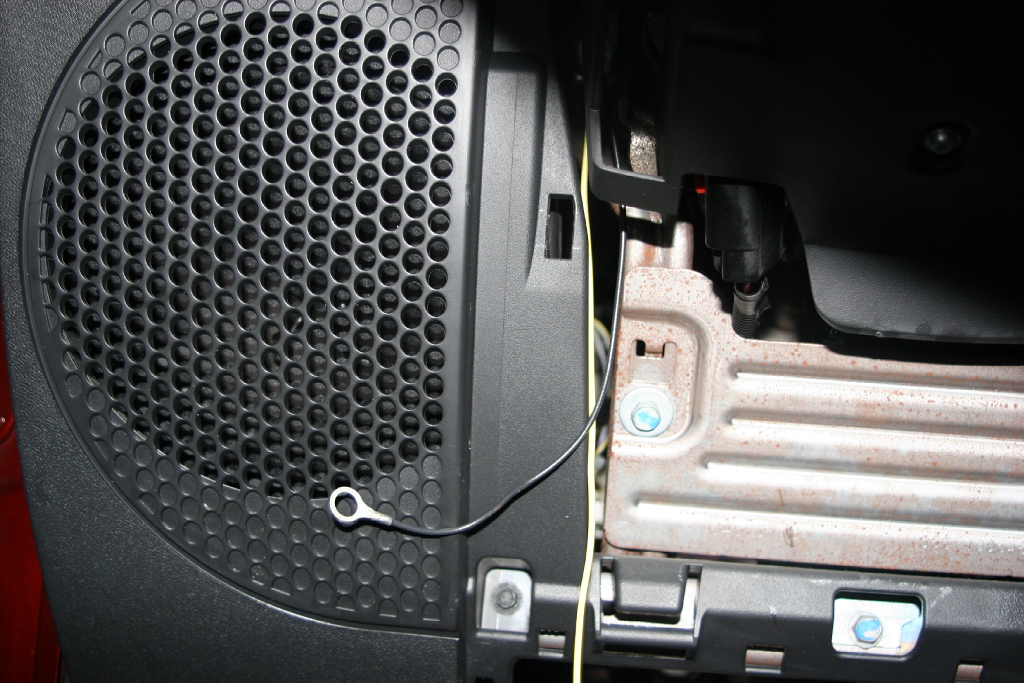
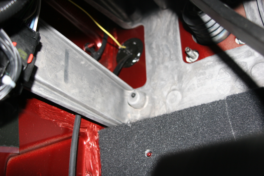
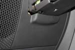
| Remove one of the 10mm bolts holding the Amplifier panel and attatch the ground wire. |
 |
 |
| Remove the side panel from the dash. It is just clipped in. You may need a flat tip screwdriver to get it out, but mine came off with my fingers. |
 |
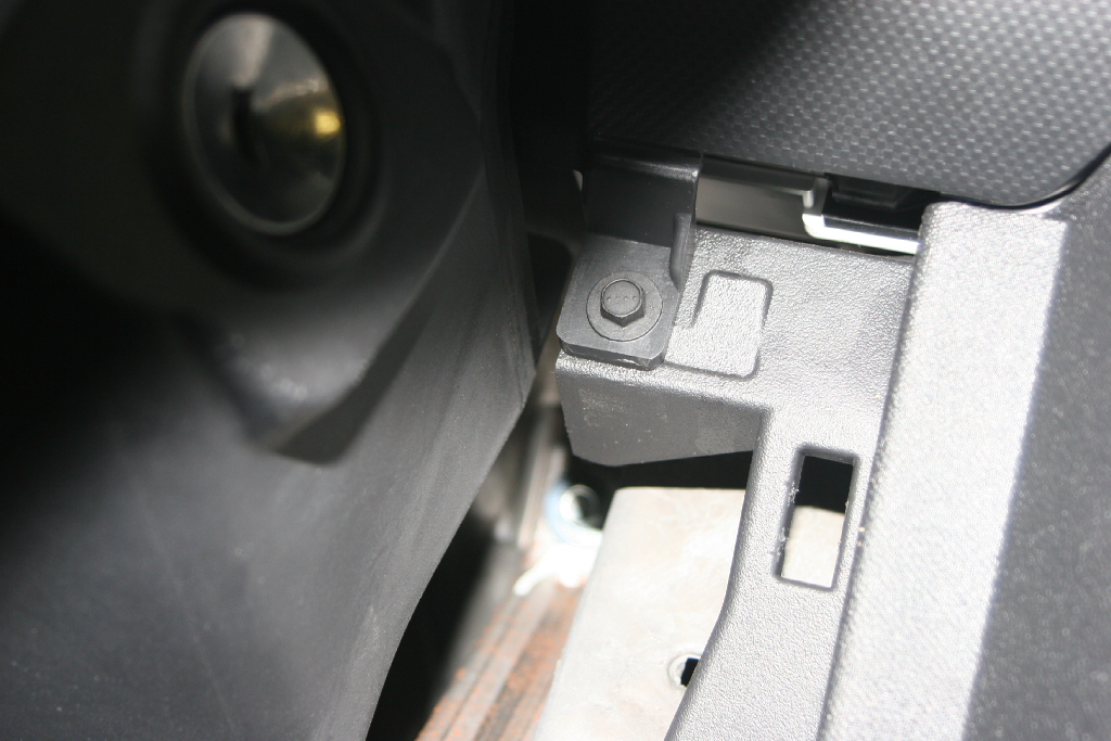
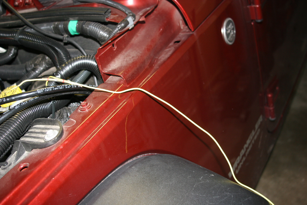
| Route the remaining wire through the dash under the vent and then down and out the firewall. I have an automatic, so the sealed clutch hole made a good routing point. There are two other points that can be accessed, one along the fender and another where the water supply for the hard top comes through, up behind the dash (this is a little more difficult to route wires through.) |
 |
 |
| Trim the excess wire. Don't cut it to short you will still need some to work with. |
 |
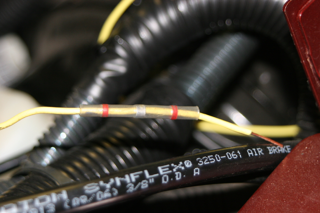
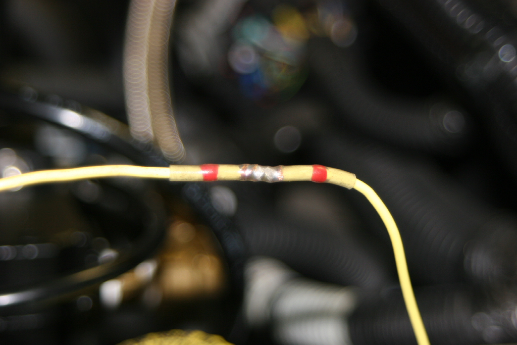
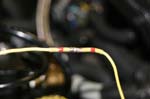
| Slide the supplied heat shrink solder connector over the wire. Splice the wires together using an audio splice. Slide the heat shrink solder connector over the splice, and heat with a heat gun (you will probably need to use high power to melt the solder). |
 |
 |
 |
 |