A friend of mine asked me to install a Teraflex 2.5" suspension lift on his 2008 Sahara. Me being the nice guy that I am and bribed with Pizza agreed to help out.I'll be interested to see how this sits against a Rock Krawler 2.5" lift. I did kind of cheat with the pictures so you may see a difference between some of them. Teraflex does recommend using after market wheels with a backspacing of 4.5" or a 1.5" wheel spacer to clear the antisway bar in the rear.
| Rear Installation: |
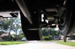
| Jack up the rear axle and support with Jack stands in front of the lower control arm frame mount point. Remove the tires |
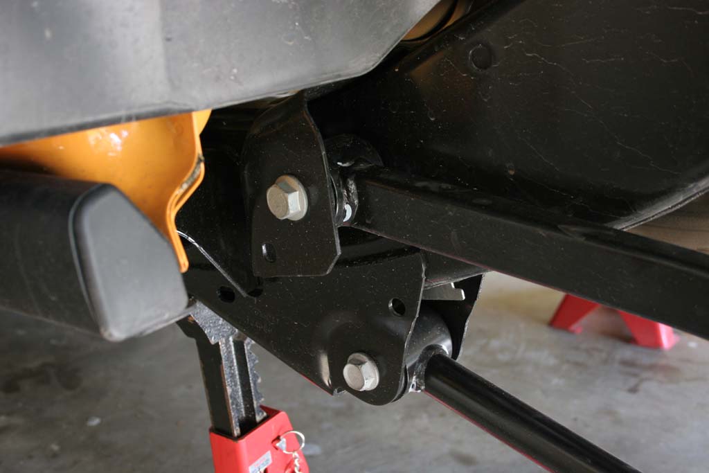
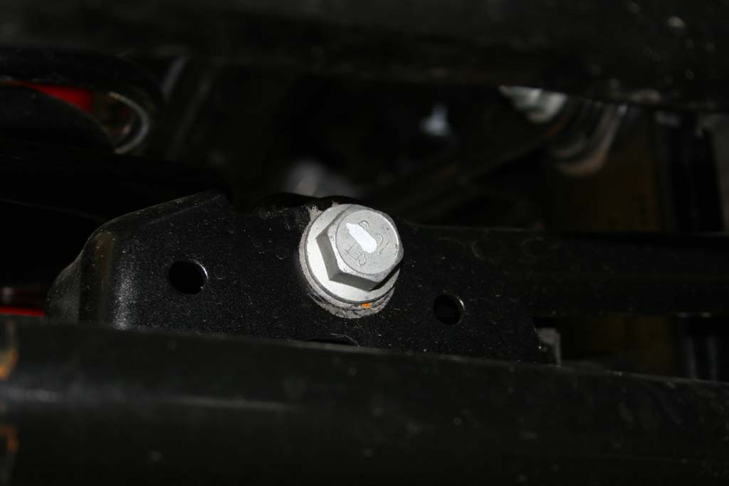
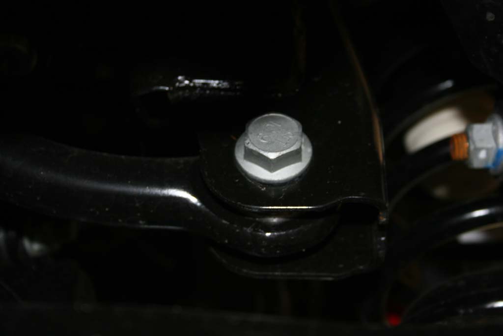
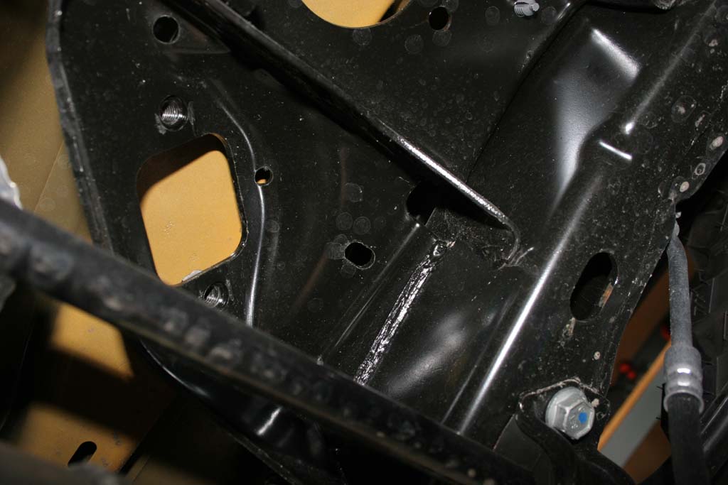
| 1. Loosen (DO NOT REMOVE) the bolts holding the upper and lower control arms. You will need a 18mm and 21mm socket and combo wrench. |
 |
 |
 |
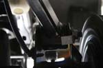
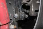
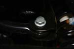
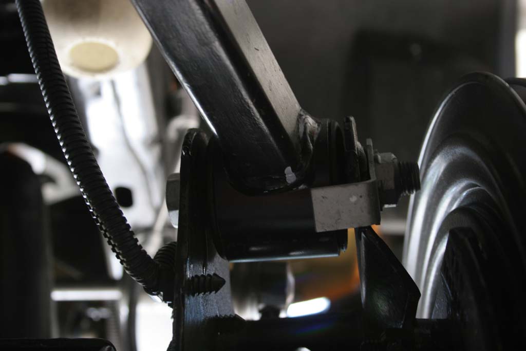
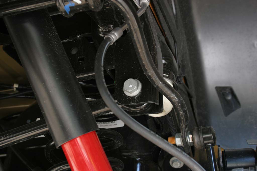
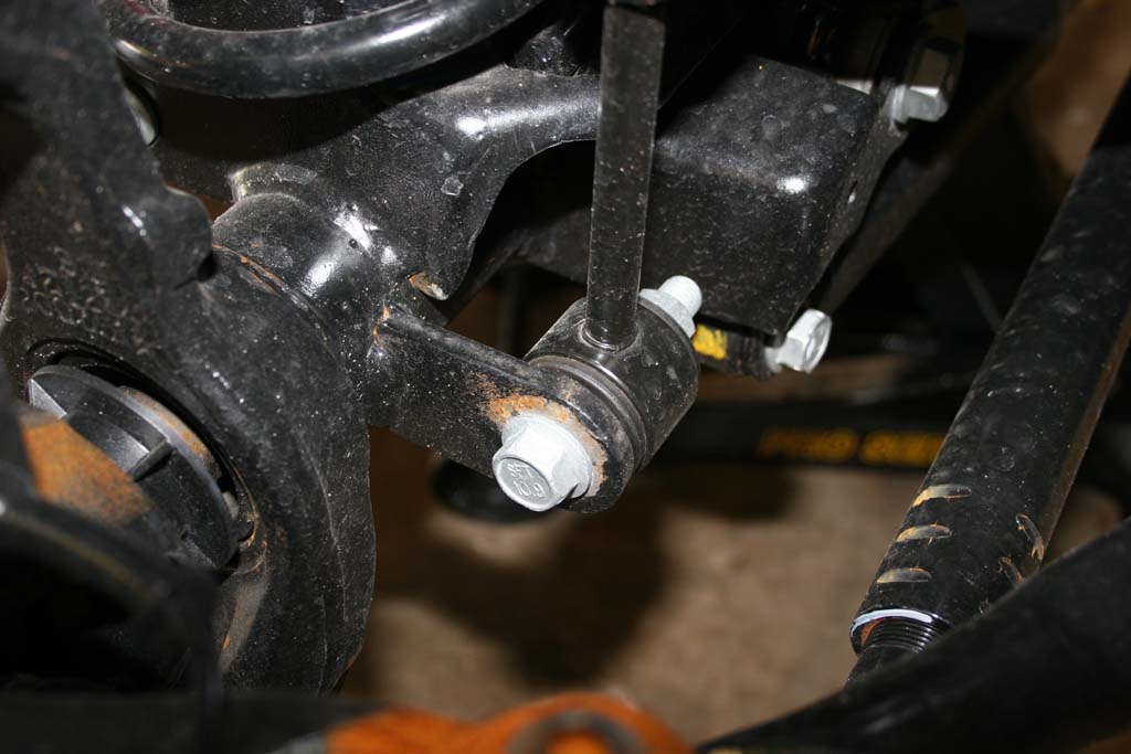
| 2. Remove the rear trackbar with a 21mm socket and combo wrench. |
 |
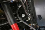 |
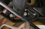
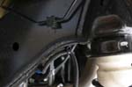
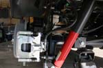
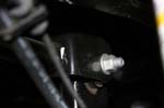
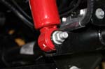
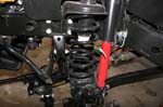
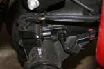
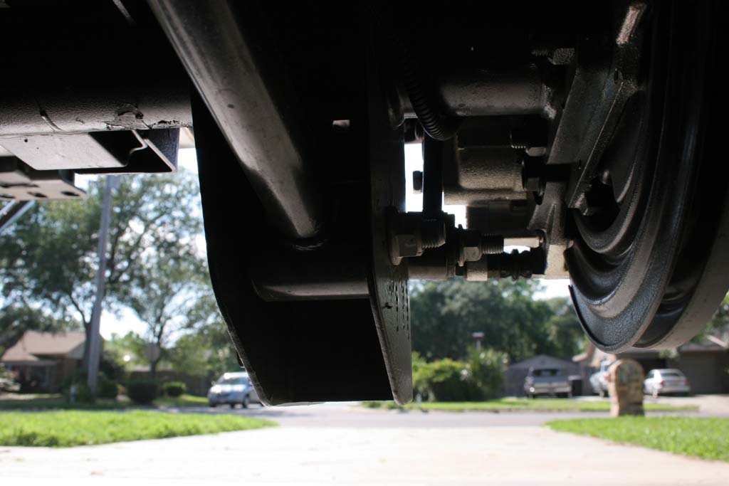
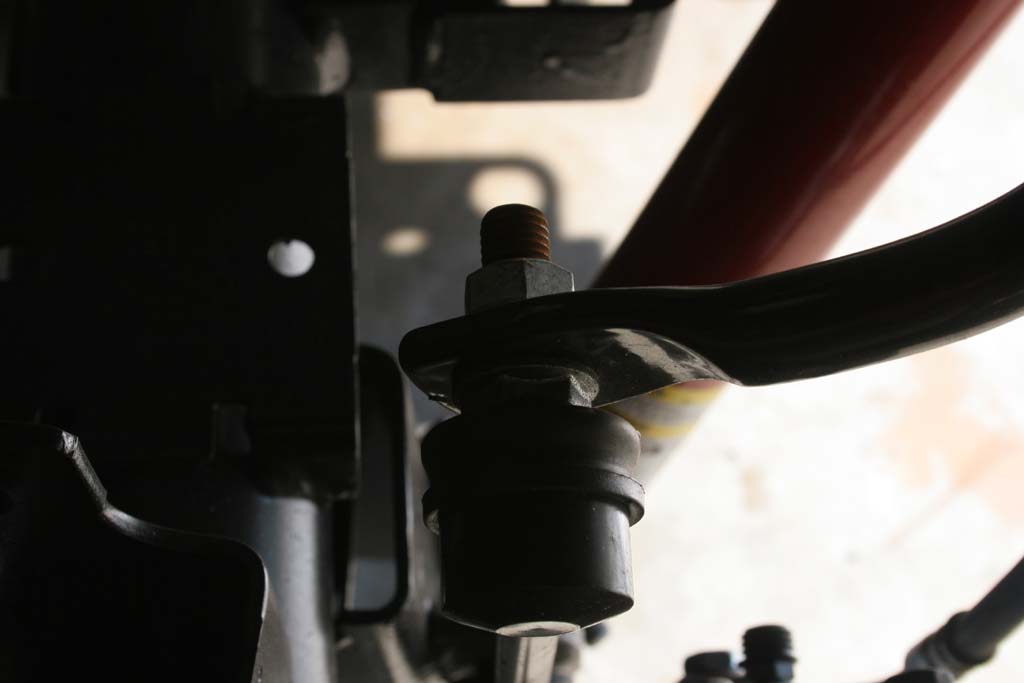
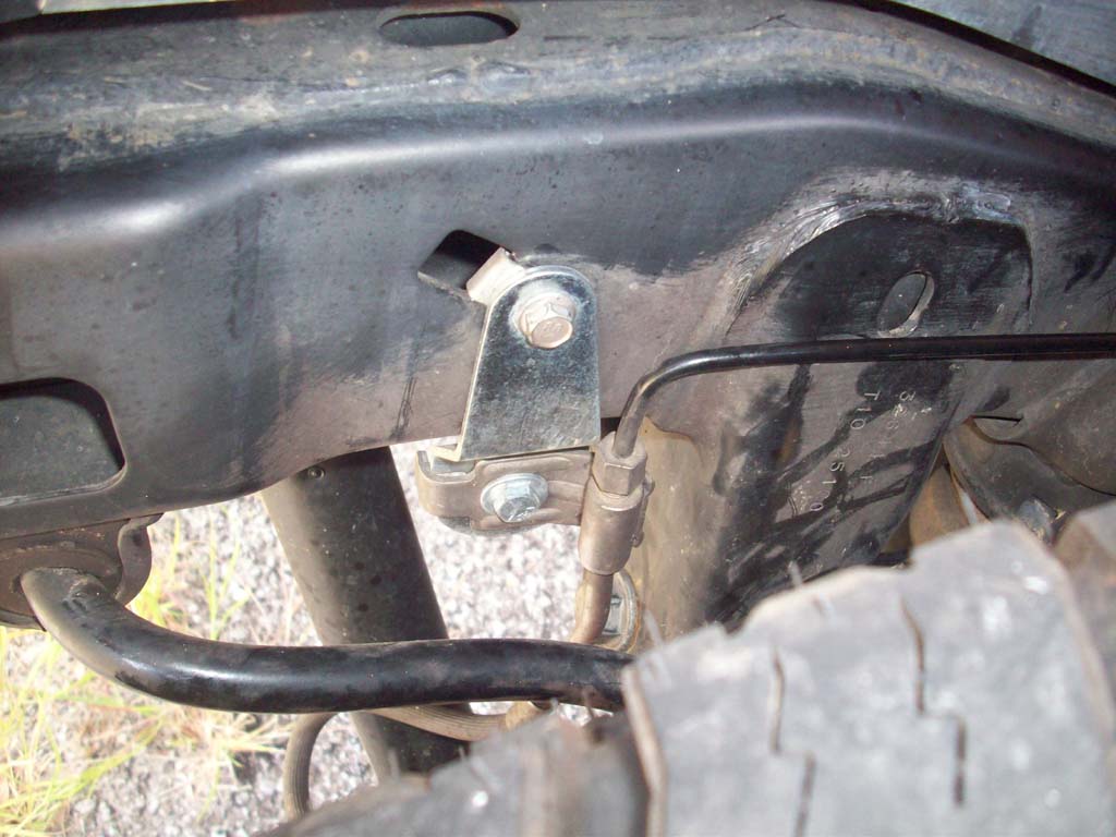
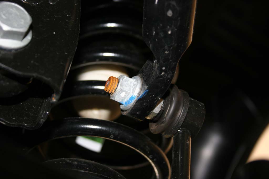
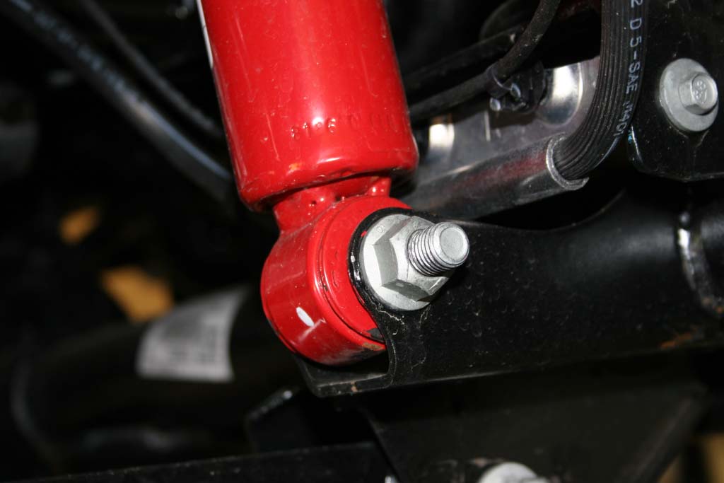
| 3. Remove the rear anti-swaybar links with a 18mm socket and combo wrench for the lower bolt and a 18mm socket and 19mm combo wrench for the upper stud. |
 |
 |
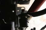
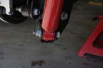
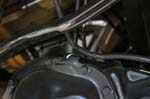
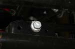
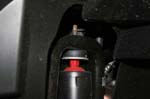
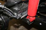
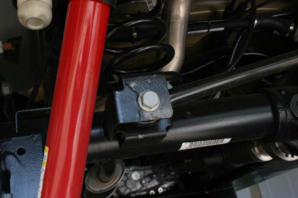
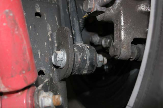
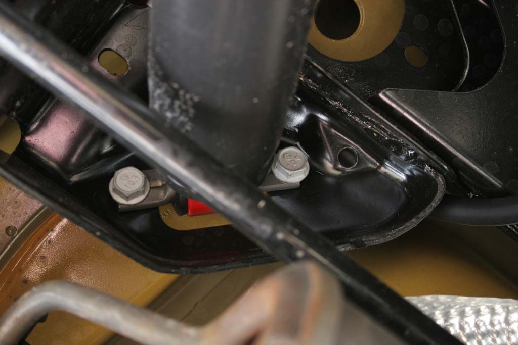
| 4. Remove the rear shocks with a 18mm socket and combo wrench for the lower bolt, and a 16mm socket and long extension for the two (2) upper bolts. Be careful, the muffler can be hot. |
 |
 |
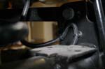
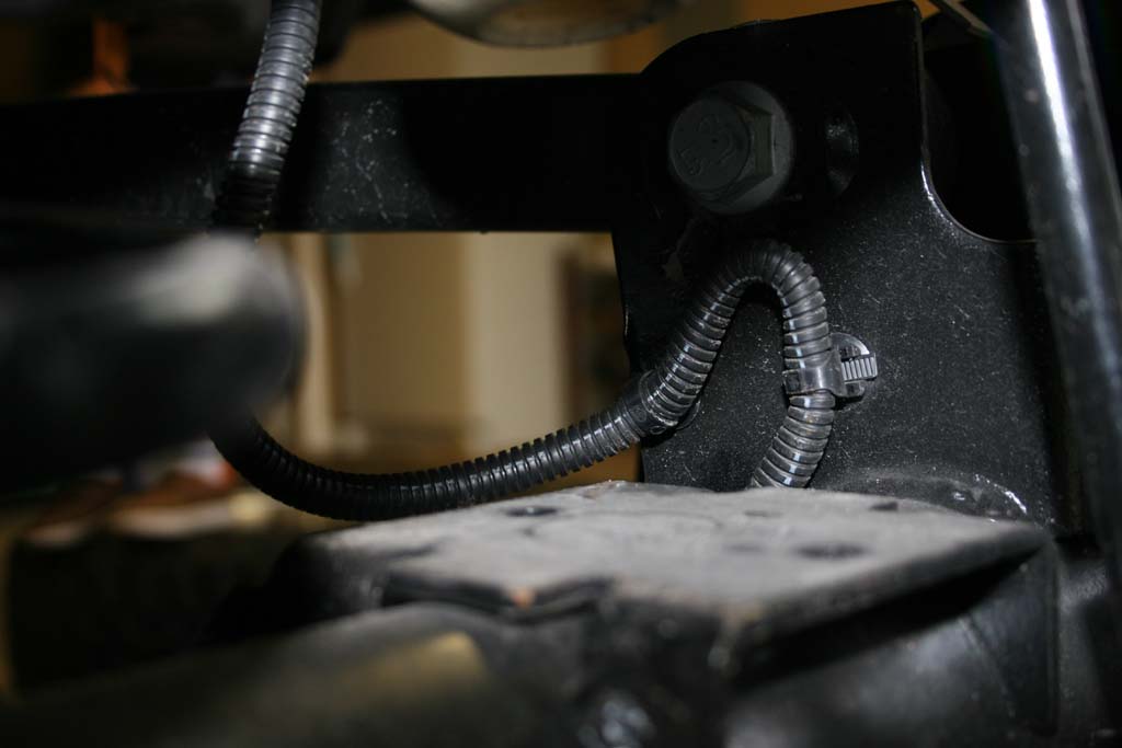
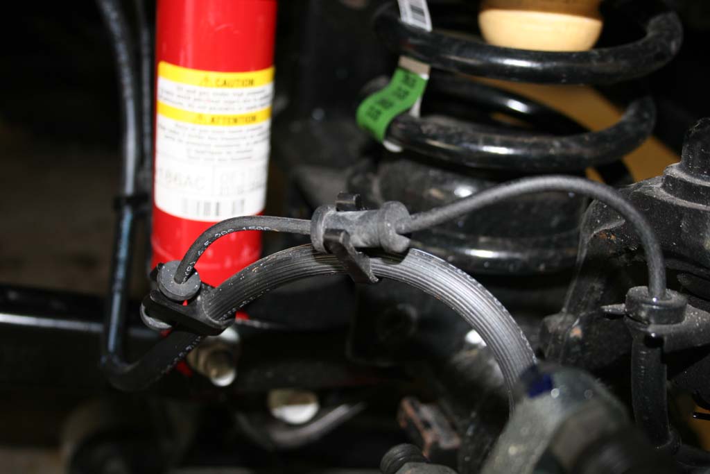
| 5. Remove the clips that hold the ABS lines to the lower control arm bracket. You will see two clips, just undo first one down from the frame. Do not undo the clip where it leads down to the axle. |
 |
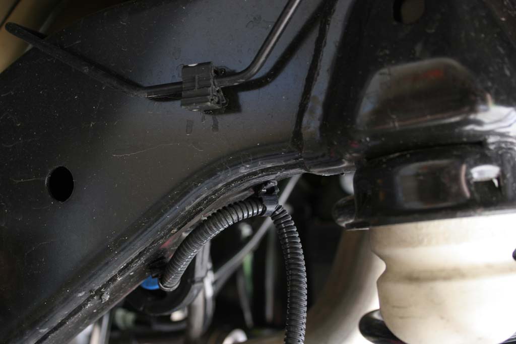
| 5a. If you need more distance, you can undo the clip that is up on the frame. |
 |
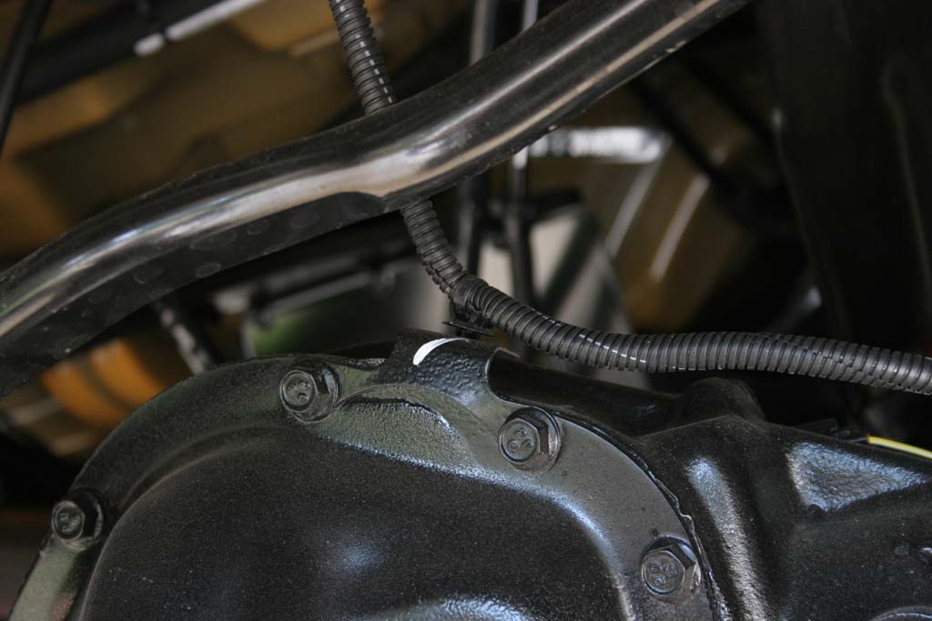
| 6. If you have a Rubicon model, unclip the locker line from the top of the differential. |
 |
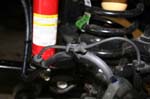
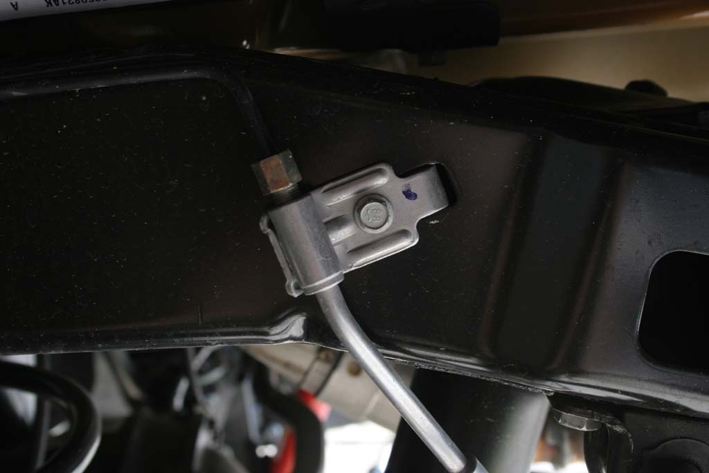
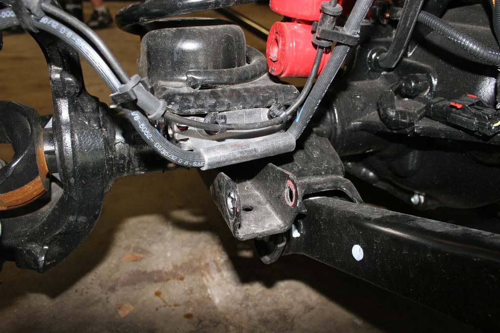
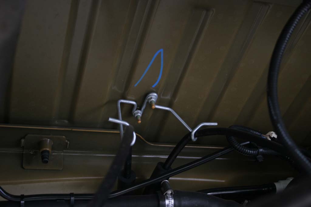
| 7. Unbolt the brake line brackets by removing the bolt with a 10mm socket. |
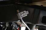 |
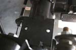
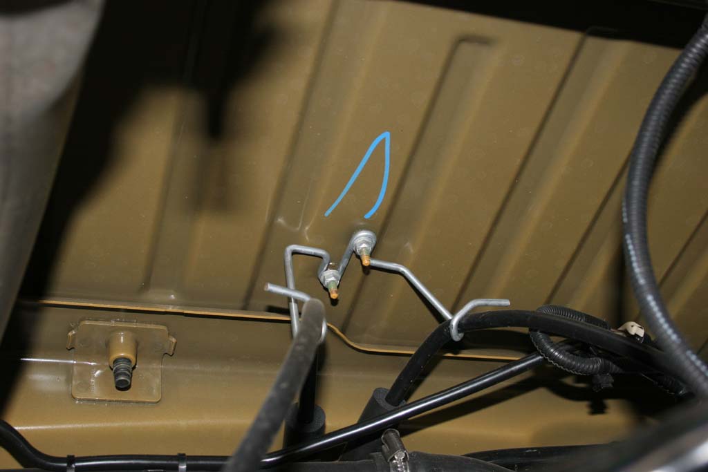
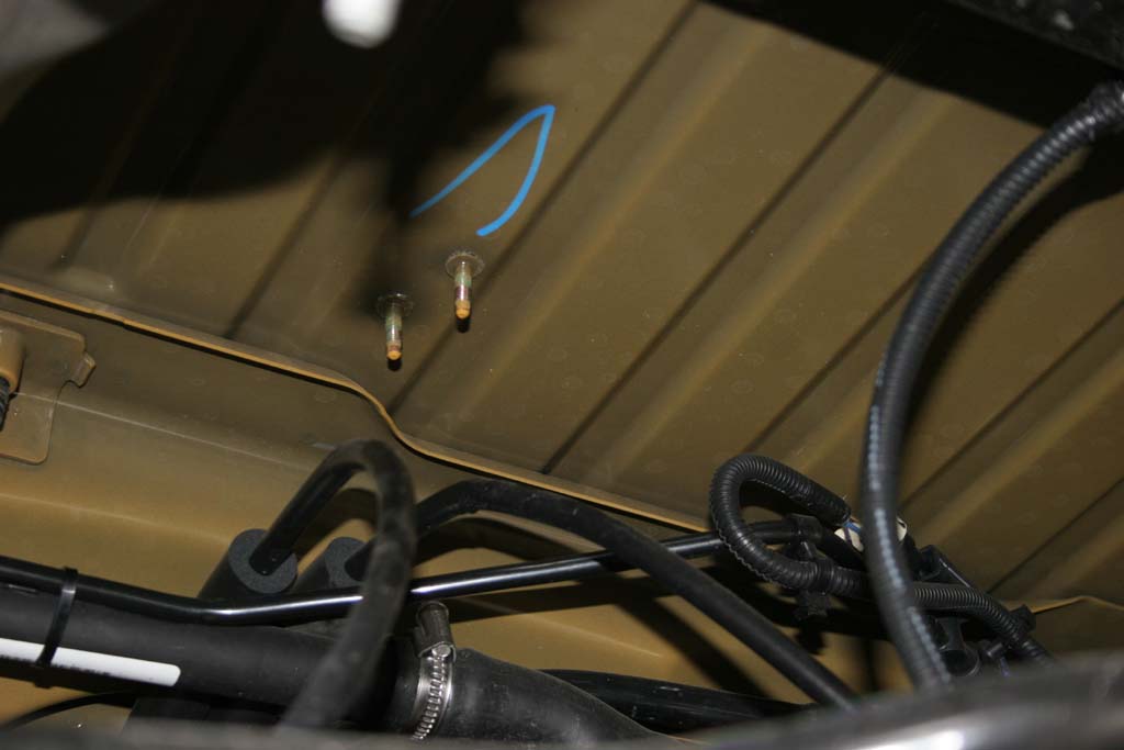
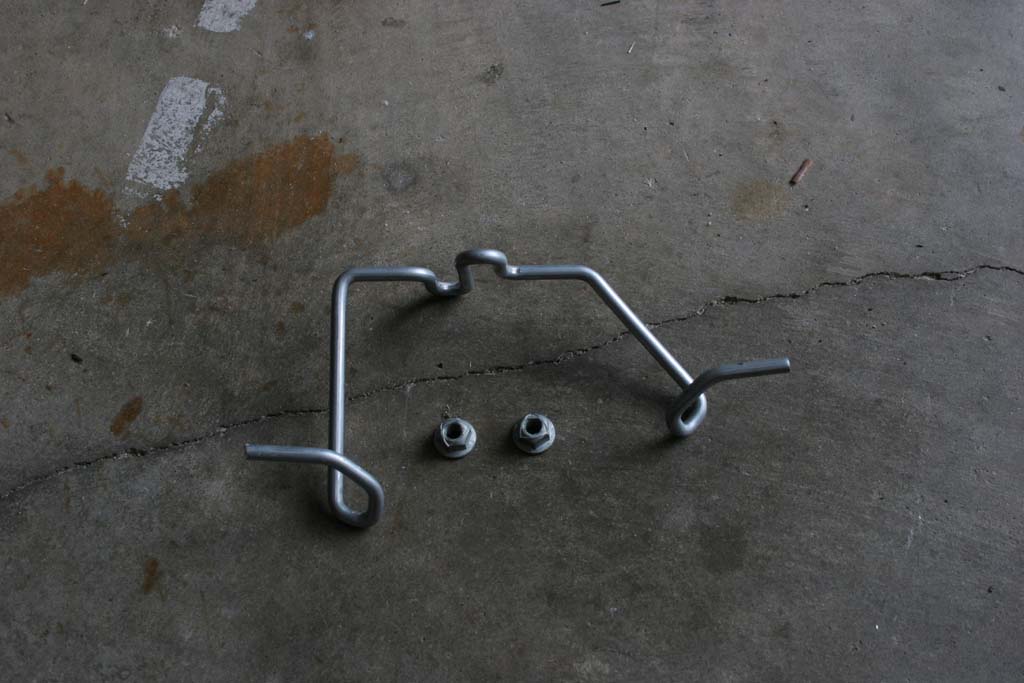
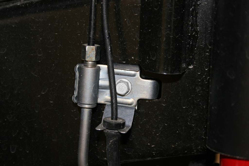
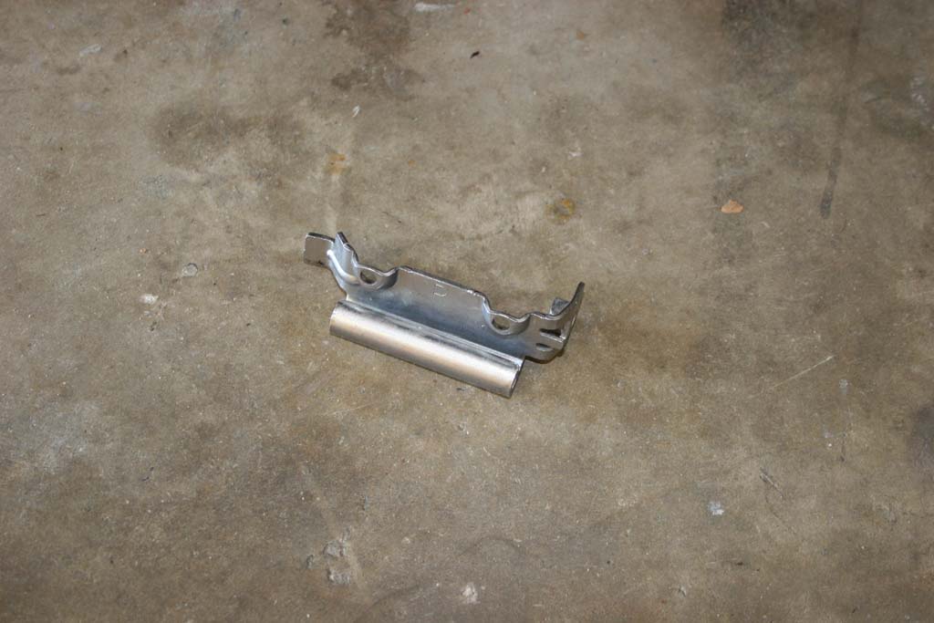
| 8. Unbolt and remove the parking brake bracket with a 10mm deep well socket. |
 |
 |
 |
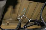
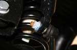
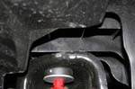
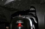
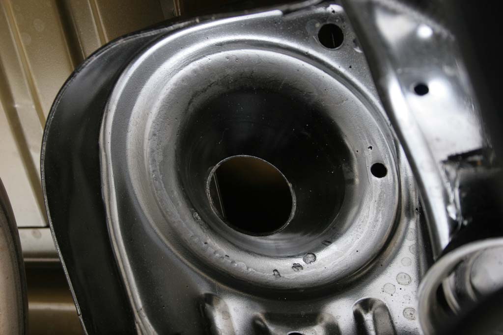
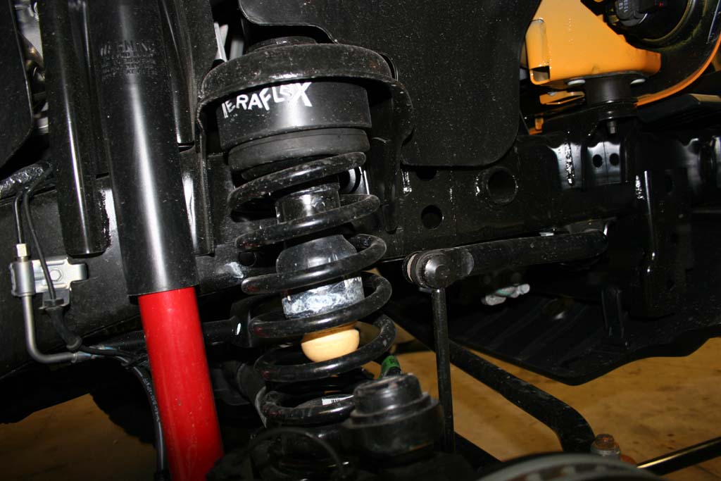
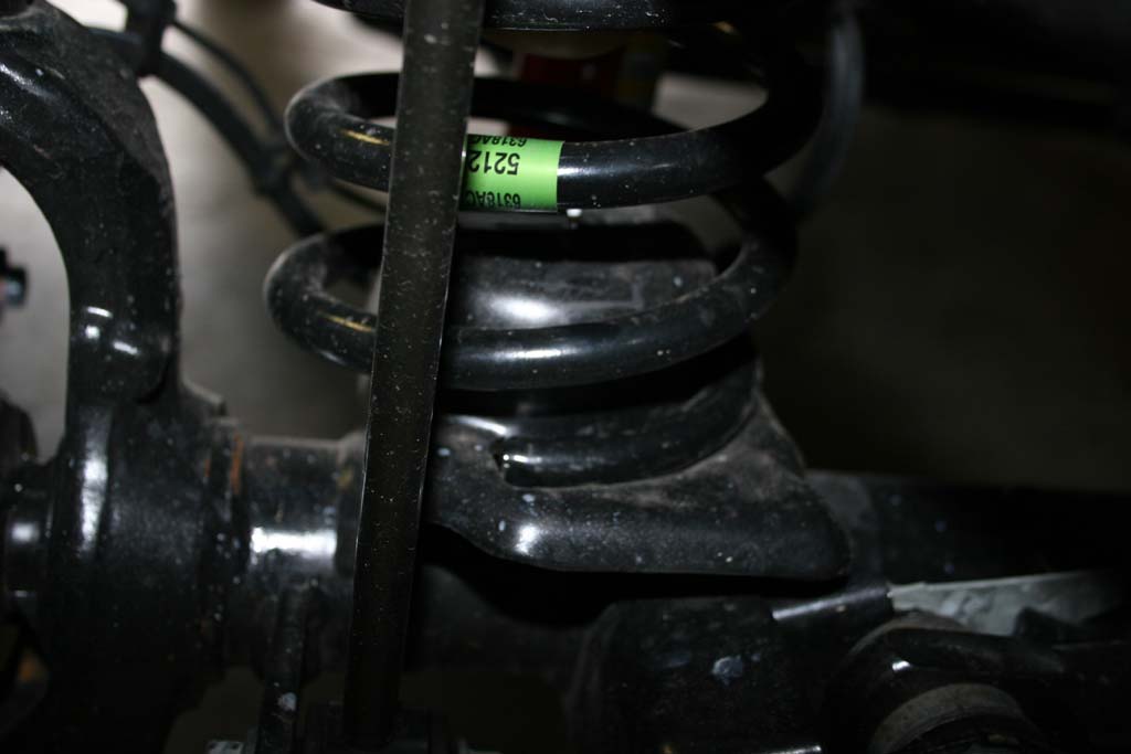
9. Lower the rear axle far enough to remove the springs. Make sure you do not stretch the brake lines, abs wires, or locker wires. The axle vent line will probably pull off it's fitting on the axle. Probably a good time to visit extending the axle vent fittings. Remove the springs, noting which side they came out of. I have run into one instance where the springs had different part numbers.
Note: Teraflex says to be careful not to let the coils fall out as you lower the axle. Great if your working on a lift with axle jacks, but on the garage floor, most likely at least one is going bouncing and rolling across the floor. |
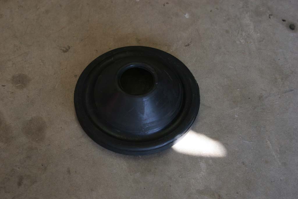
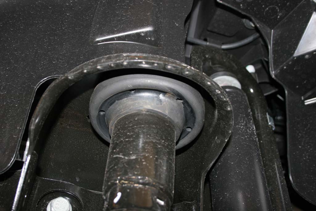
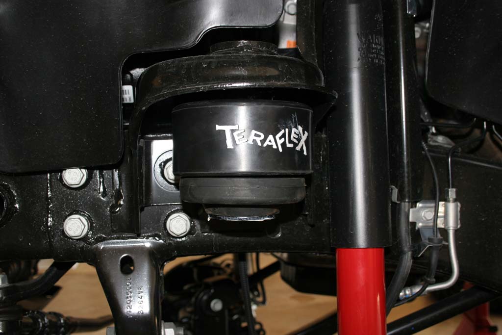
| 10. This is the point where you look around for where the upper spring isolator bounced off to when you removed the springs. I had one fall out when I wasn't looking, roll out of the garage and into the flower bed. |
 |
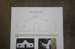
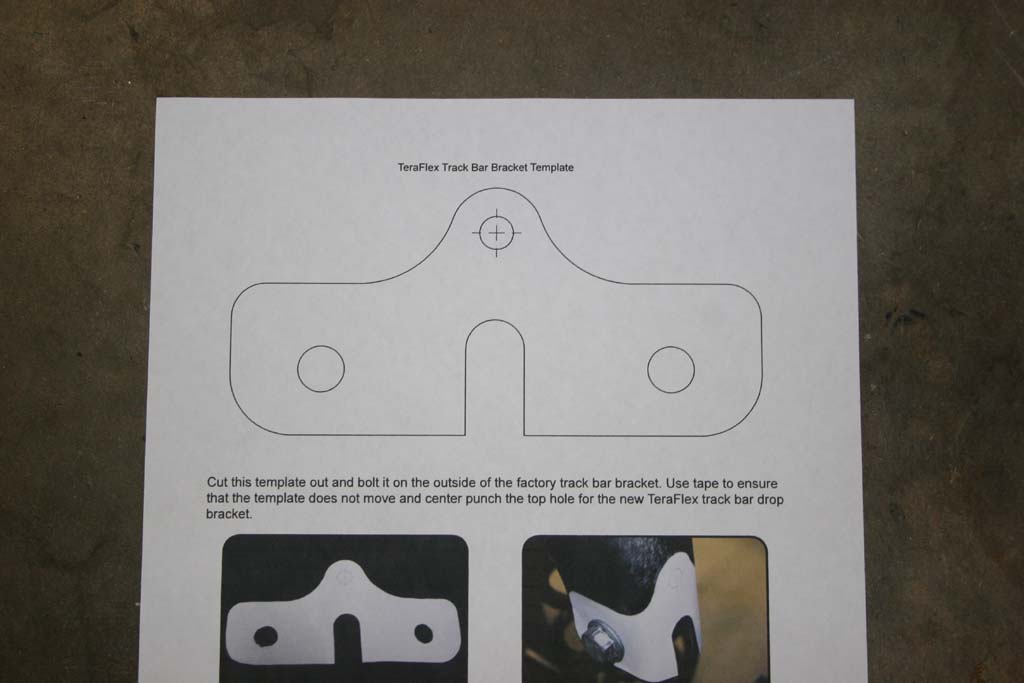
| Alt a. Cut out the supplied template. |
 |
|
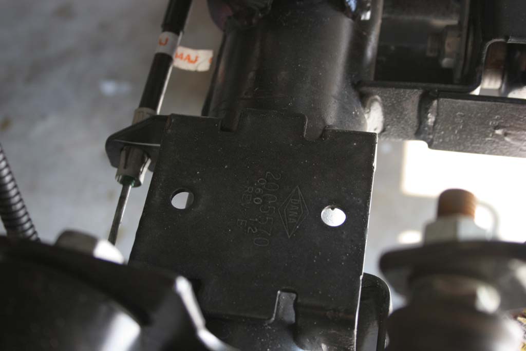
| Alt.b. Use the template included in the instructions to mark and drill a 3/8" hole in the factory track bar bracket on the frame. |
|
|
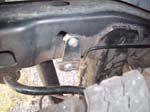
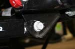
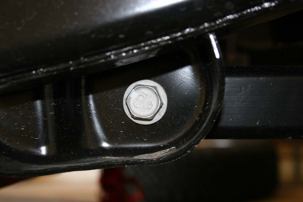
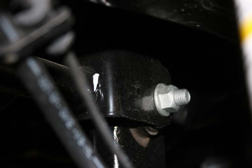
Alt b. Fit the new bracket around the existing track bar bracket and install the 14mm bolt, washer and nut through the drilled hole.
Note: Bolt head goes out. |
|
|
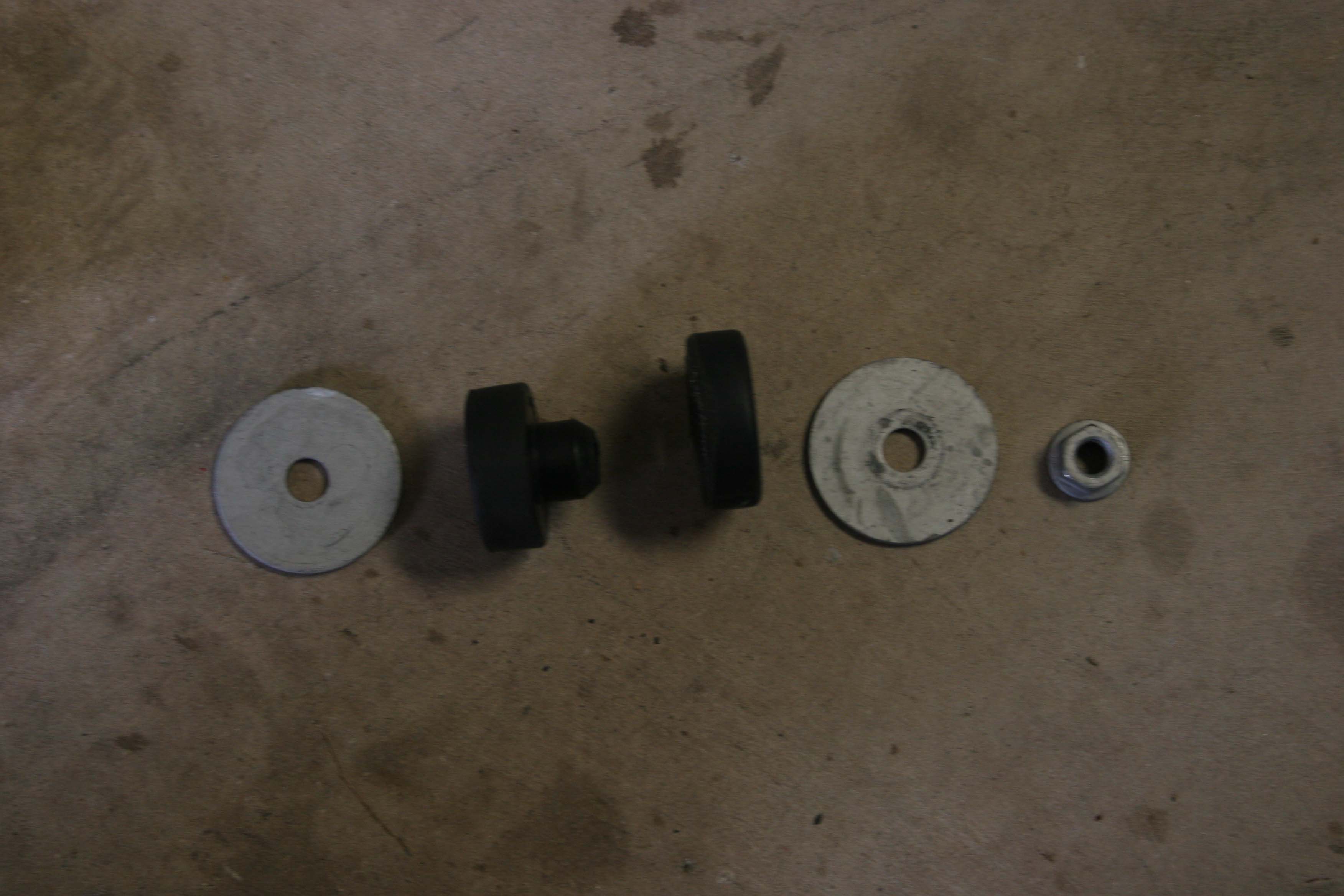
| Alt c. Install the provided bolt, washers, crush sleeve and nut into the old track bar mount. Torque the 14mm bolt to 45 ft/lb and the trackbar bolt to 125 ft/lb. |
|
|
| 14c. Reinstall the factory trackbar. You will need a 21mm socket and combo wrench. |
| |
|
|
| |
|
|
| |
|
|
| |
|
|
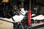
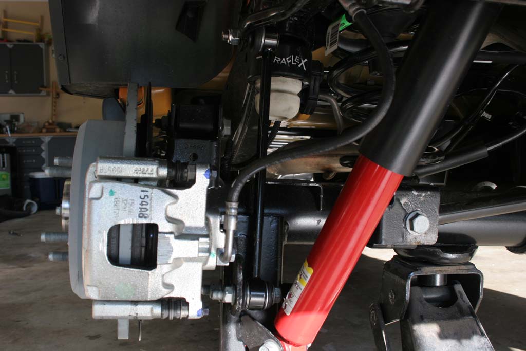
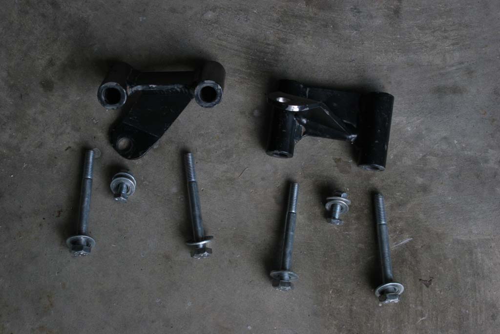
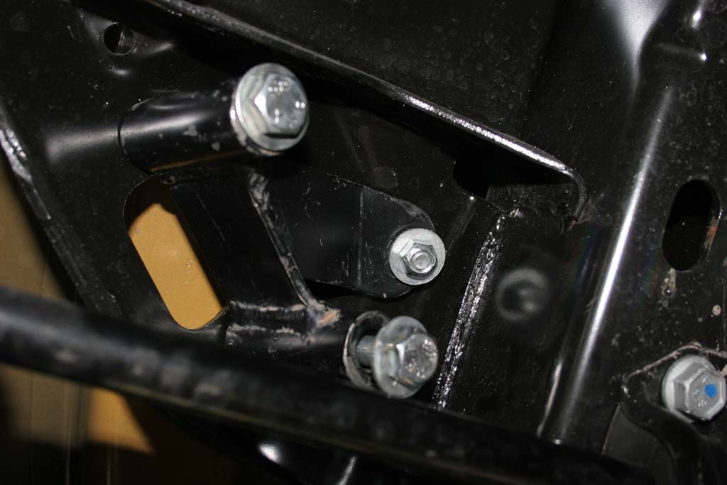
| 15. Install the brake line drop brackets with the provided hardware. You will reuse the bolt that you removed from the factory bracket to secure the Teraflex drop bracket in place. Ensure that the bracket is flush with the frame and that the bend is pointed towards the inside of the Jeep. |
|
 |
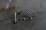
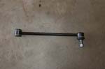
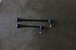
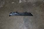
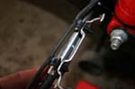
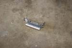
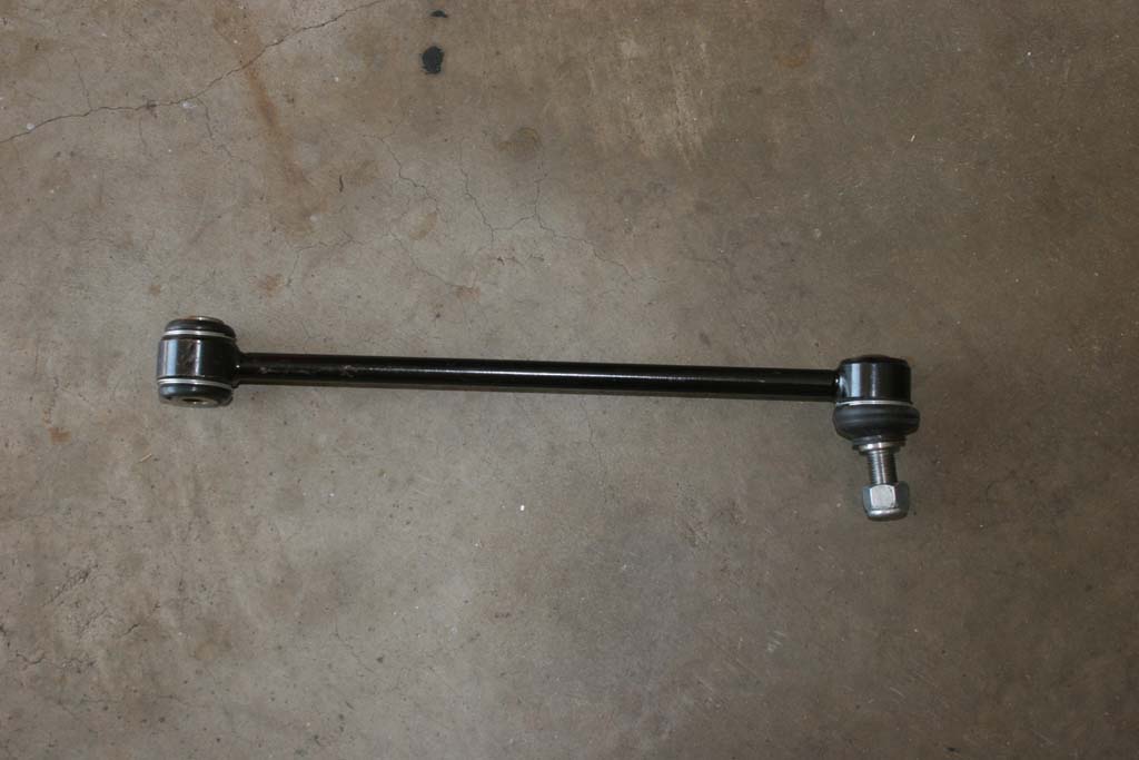
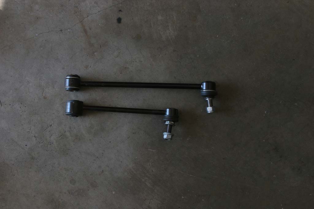
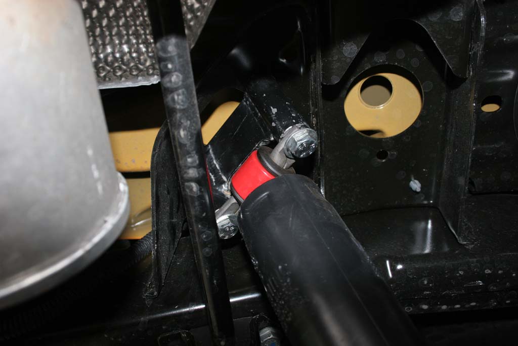
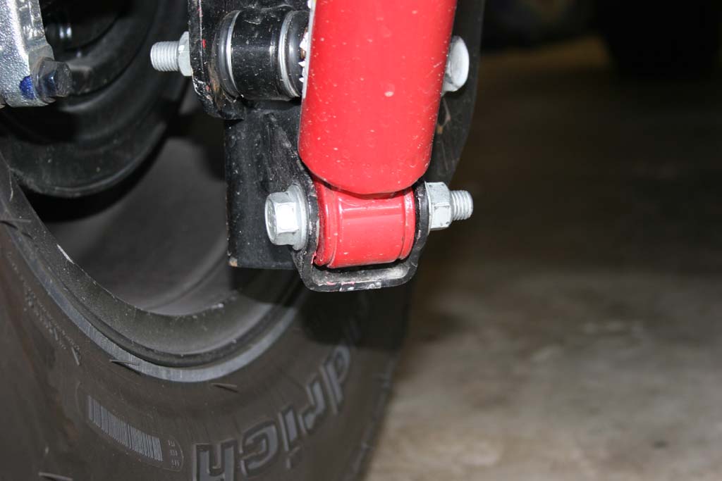
16. Install the new rear anti-swaybar links on the inside of the axle bracket. The head of the bolt should be on the shockside of the anti-swaybar link so that the excess threads will not interfere with the shock.
Note: I have the older style links that are wider than the new Heim joint style links. The new links come with mounting hardware to attach them to the anti-swaybar. |
 |
 |
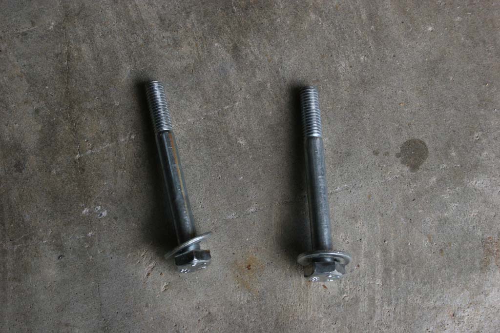
| Size Comparison. The old rear anti-swaybar links will be used on the front. |
 |
| |
|
| |
|
|
| |
|
| |
|
|
| |
|
|
| |
|
| |
|
|
| |
|
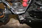
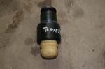
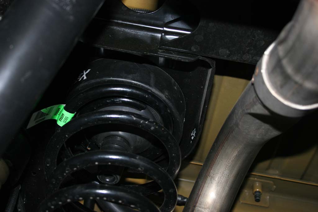
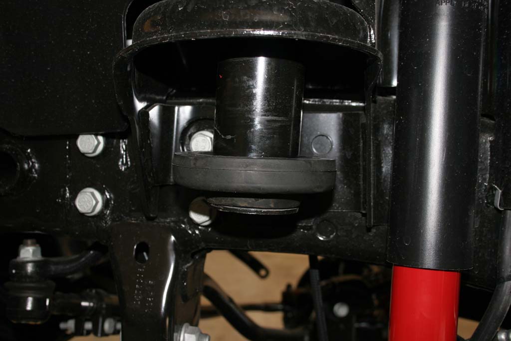
| 20. The new kit has a block that installs on the axle. The overhang part of the block will point forwards. Just install the two bolts into the provided holes in the axle pad. You will need a 1/2" socket and combo wrench. |
 |
|
|
| 21. Reinstall the tires and check for clearance between the rims and any bolts. Lower the Jeep to the ground and tighten the upper control arm bolts, lower control arm bolts, and track bar bolts. |
| |
| Front Installation: |
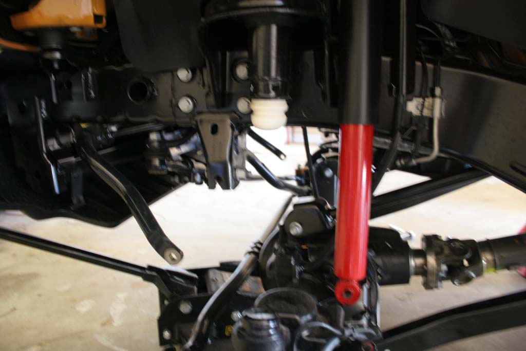
| Jack up the front axle and support with Jack stands in behind of the lower control arm frame mount point. Remove the tires |
| 1. Loosen (DO NOT REMOVE) the bolts holding the upper and lower control arms. You will need a 18mm and 21mm socket and combo wrench. |
 |
 |
 |
| 2. Loosen the front trackbar with a 21mm socket and combo wrench. |
 |
 |
| 3. Remove the front anti-swaybar links with a 18mm socket and combo wrench for the lower bolt and a 18mm socket and 19mm combo wrench for the upper stud. |
 |
 |
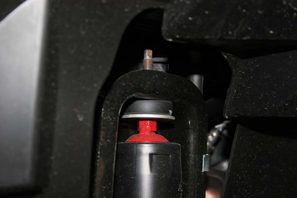
| 4. Remove the front shocks with a 18mm socket and combo wrench for the lower bolt, and a 16mm combo wrench for the upper nut. You can use a 5/8" wrench to hold the welded nut on the top of the shock while you unscrew the nut. |
 |
 |
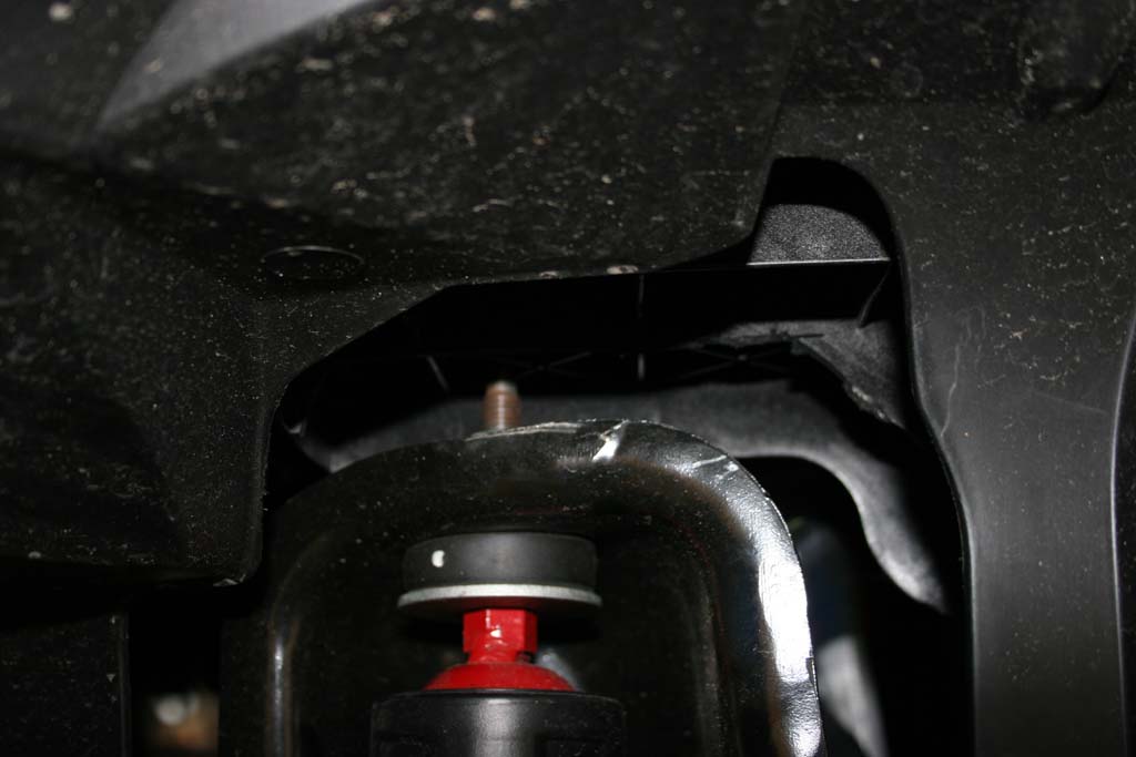
| 4a. The Passenger side on the 2012 JK's presents an interesting problem. The plastic tray sits nearly on top of the shock tower. |
|
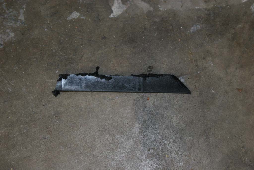
| 4b. Just use a Dremel tool, or a hacksaw blade to remove the plastic from just under the top webs and the length of the shock tower. Now you can easily get the 16mm combo wrench to the top nut on the shock. I did have to use another 16mm combo wrench to hold the welded nut on top of the shock to loosen up the top one. |
 |
 |
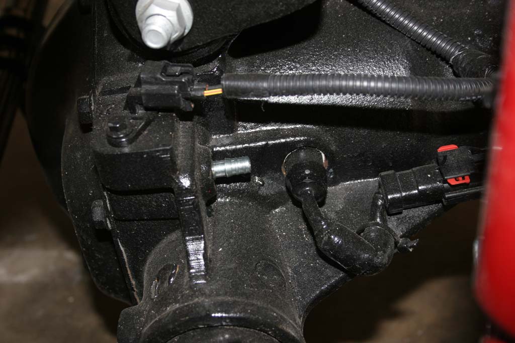
| 5. If you have a Rubicon model, unclip the locker line from the top of the differential. It is located on the side of the upper control arm. |
|
| 6. Unbolt the brake line brackets by removing the bolt with a 10mm socket. You do not need to do this on the 2012's, they made a slight change to the brake line in the front, see below. |
 |
| 6a. Unbolt the brake line brackets by removing the bolt with a 10mm socket. Pull the bracket out of the hole that the tab on the bracket is intalled into on the inside. |
 |
 |
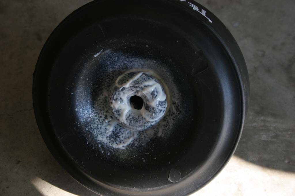
| 6b. Carefully cut and remove the zipties holding the ABS line to the bracket. Spray some silicone lube, or WD-40 into the bracket (coat it good). Work the brake line out of the bracket through the slot. It's tight, but once you get it started it does come right out. |
 |
 |
| 6c. Reclip the ABS line into the holders on the brake line. |
 |
| 7. Lower the front axle far enough to remove the springs. Make sure you do not stretch the brake lines, abs wires, or locker wires. Remove the springs, noting which side they came out of. I have run into one instance where the springs had different part numbers. |
 |
 |
| 7a. The axle vent line will probably pull off it's fitting on the axle. Probably a good time to visit extending the axle vent fittings. |
 |
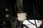
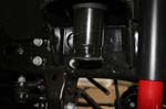
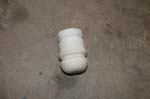
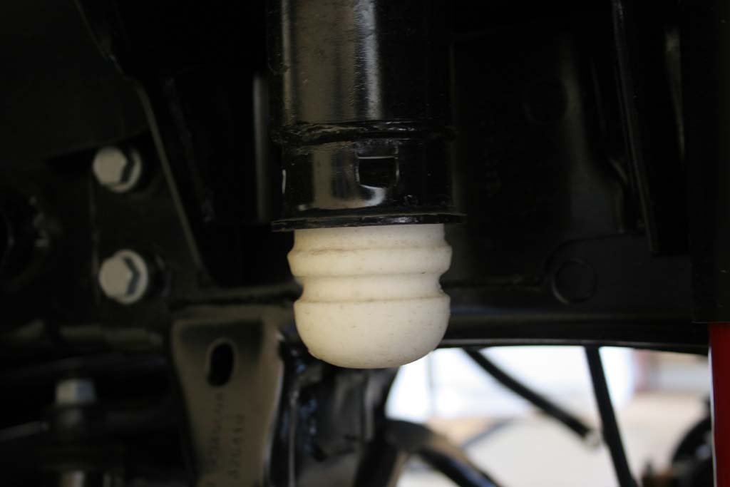
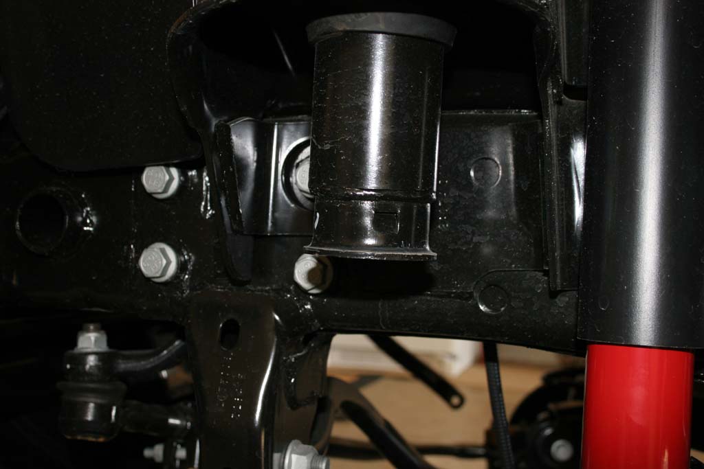
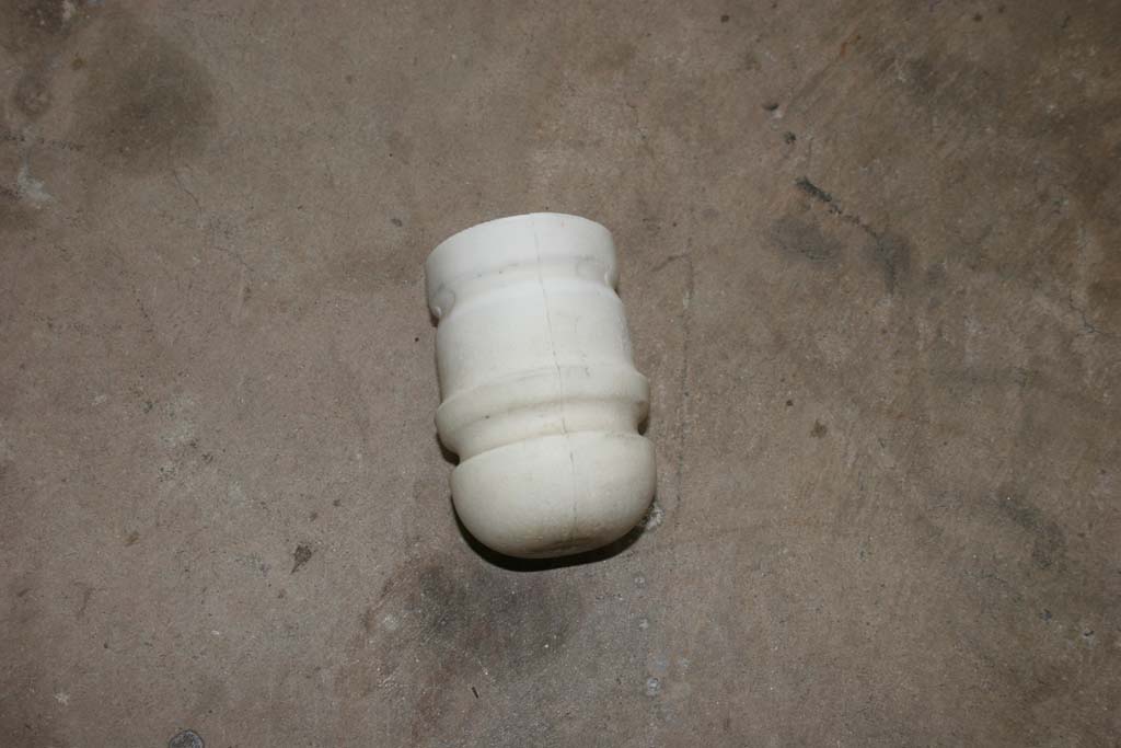
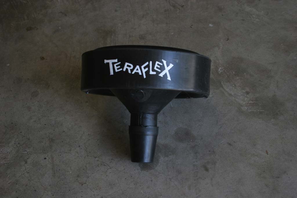
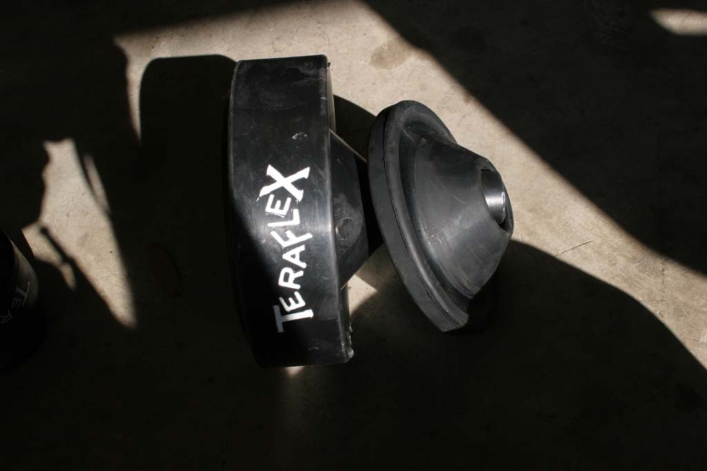
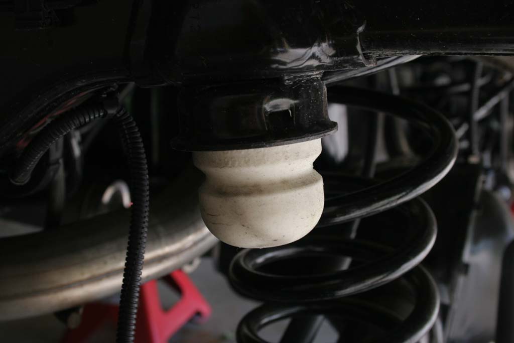
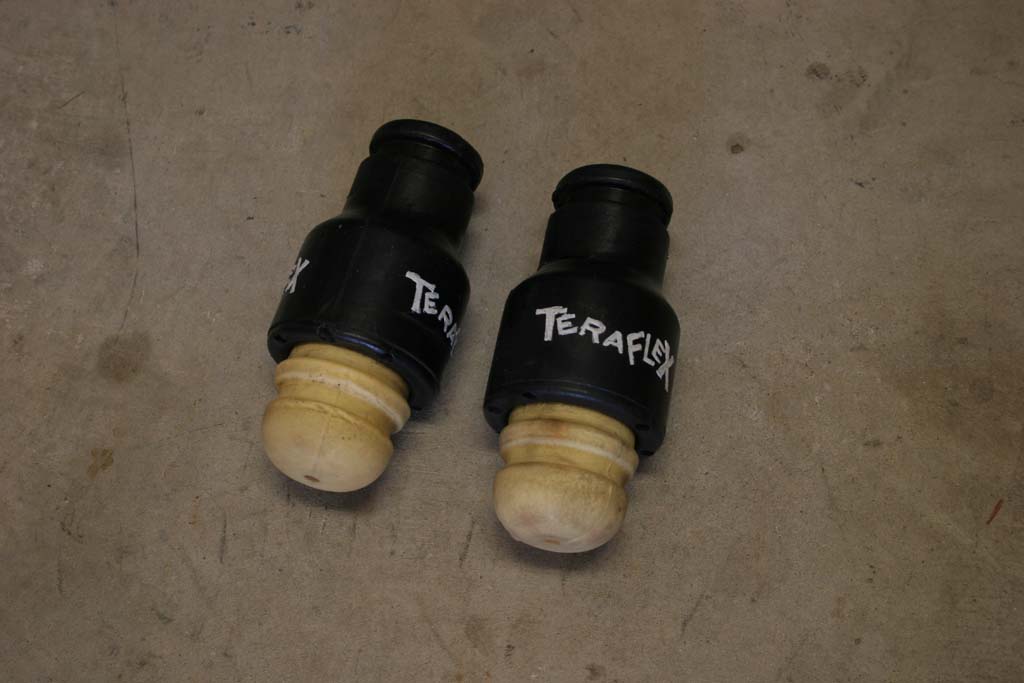
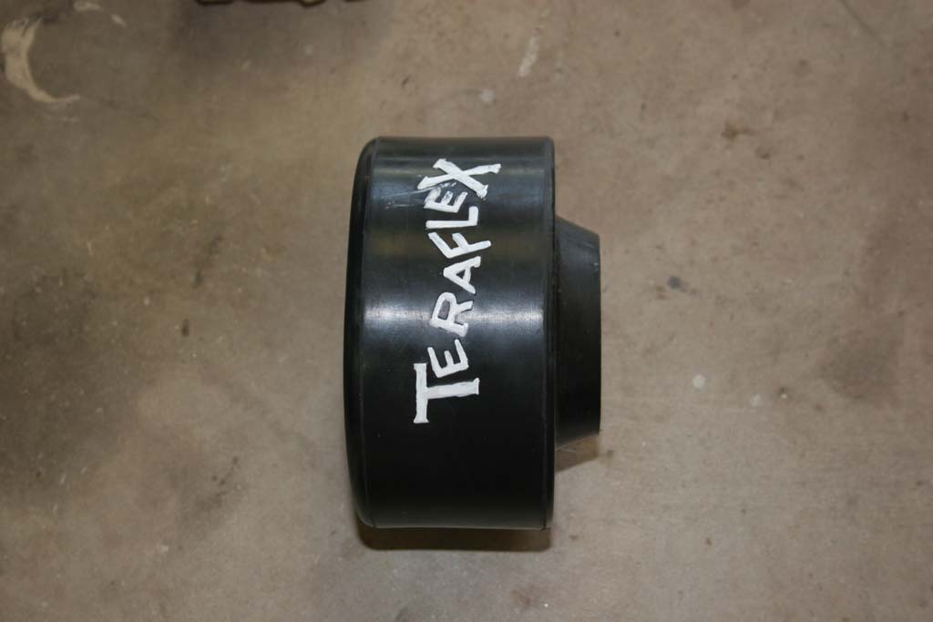
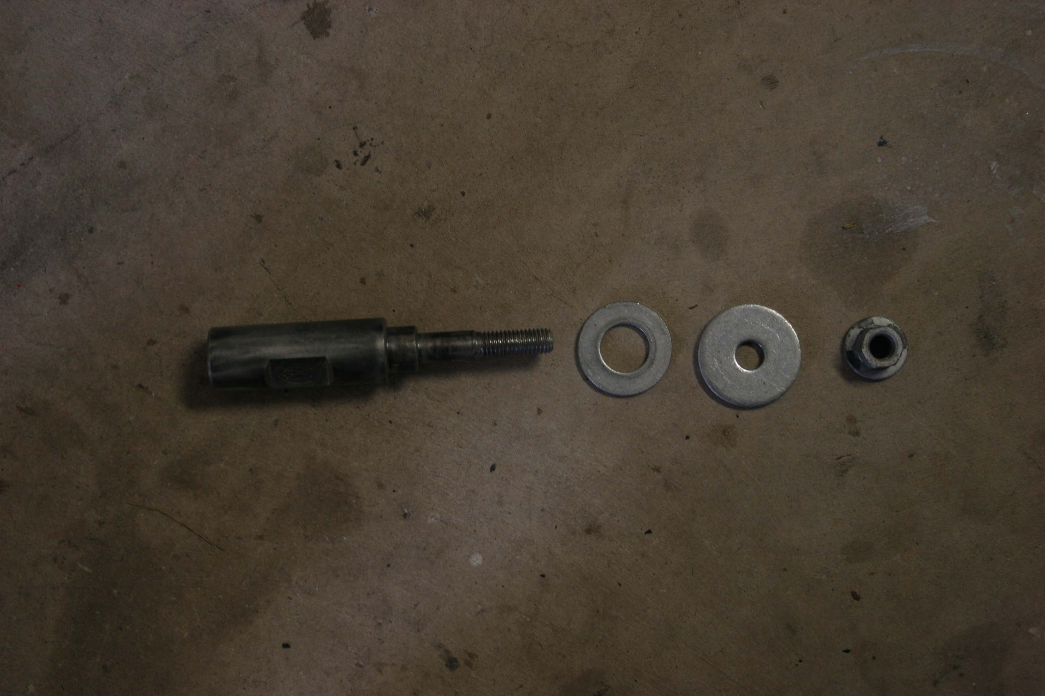
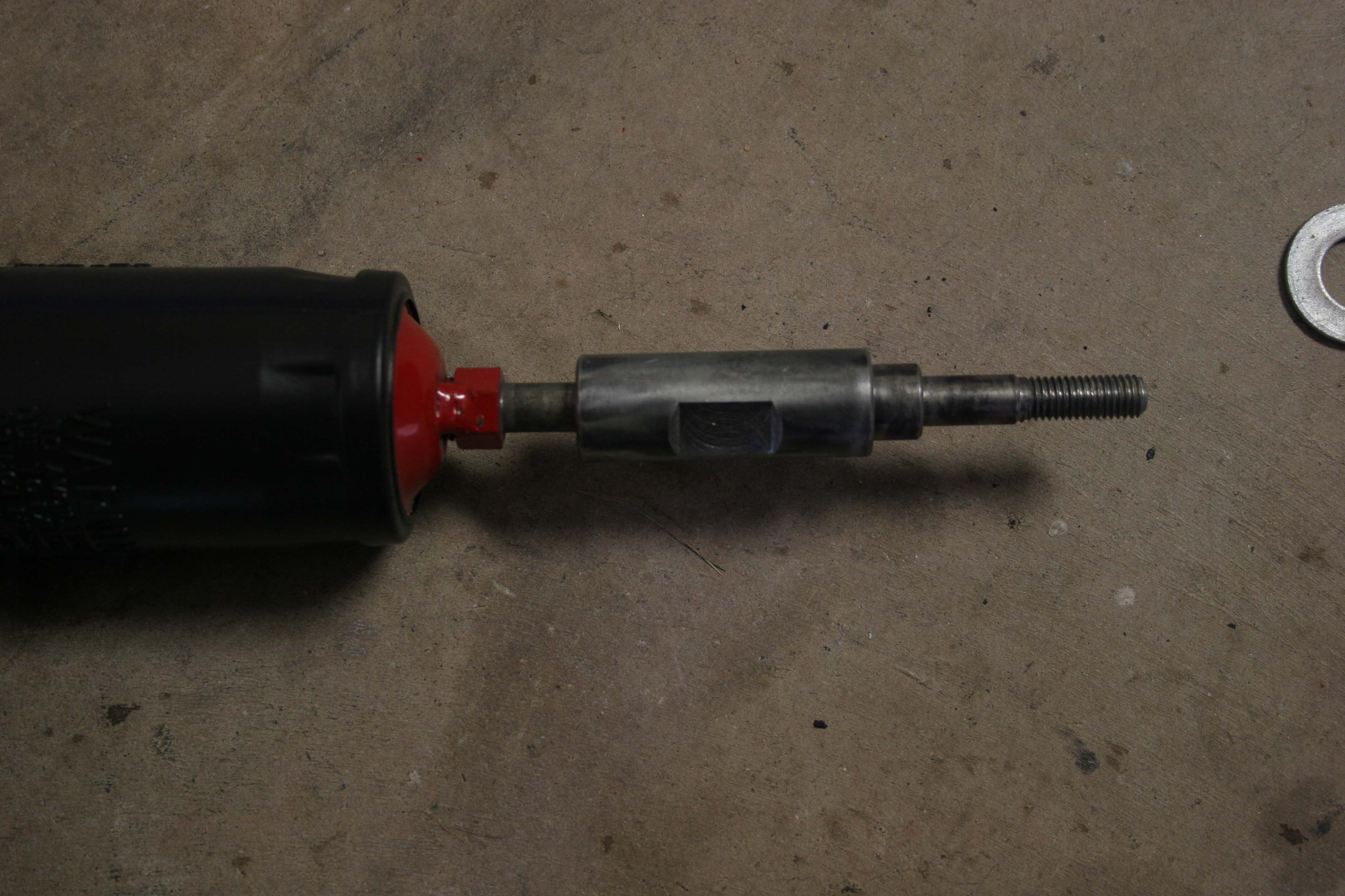
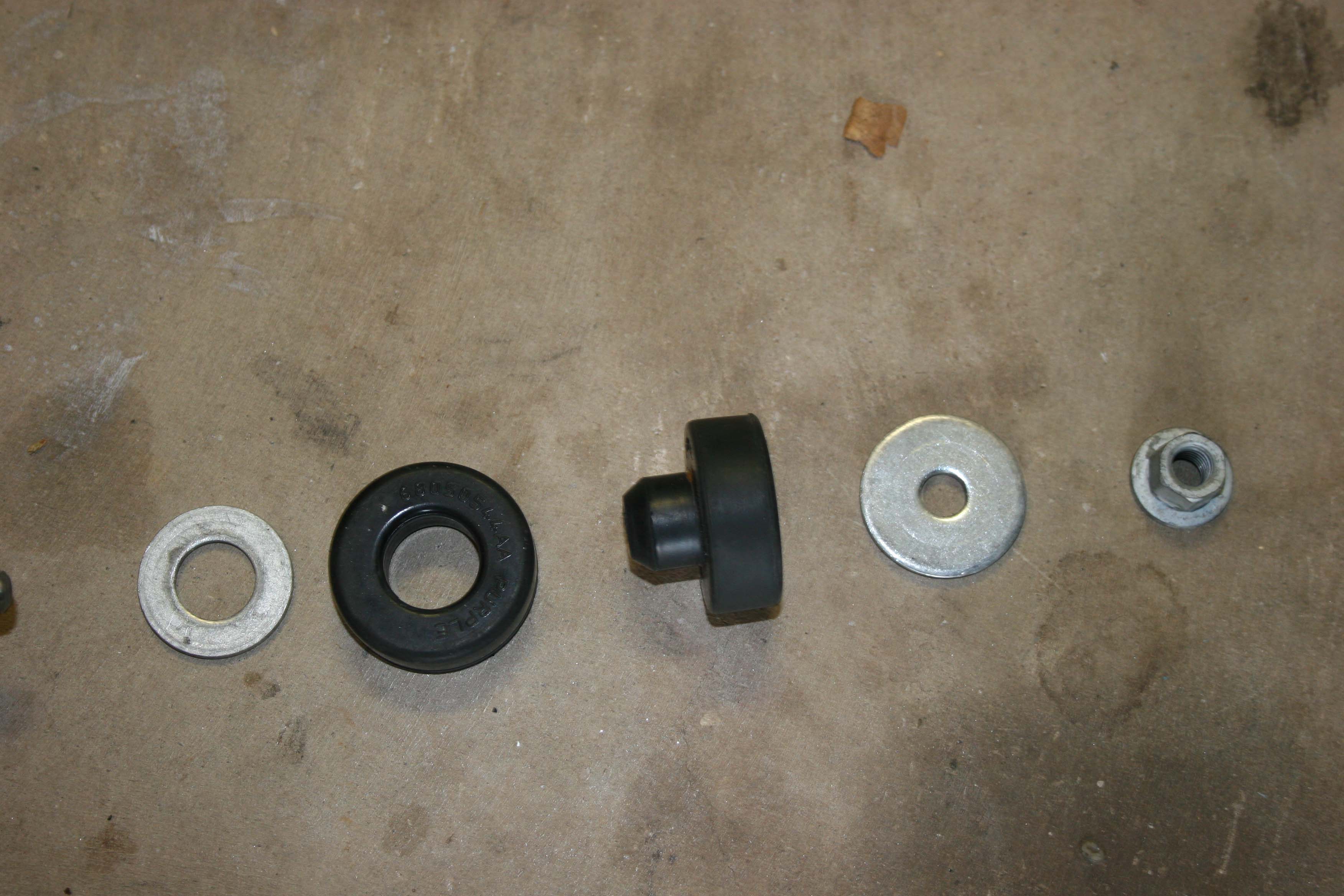
| 8. Remove the bump stop from the bumpstop cup. Just give it a twist sideways and it should pop free. |
 |
 |
| |
|
|
| |
|
|
| |
|
|
| |
|
|
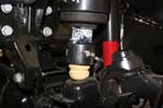
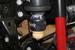
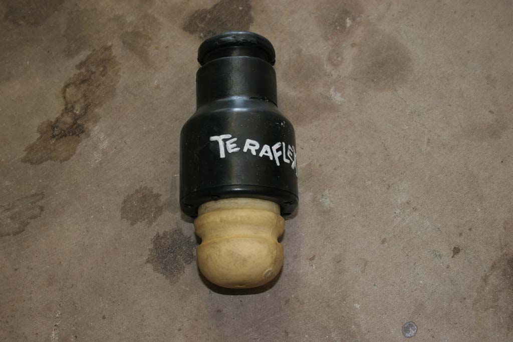
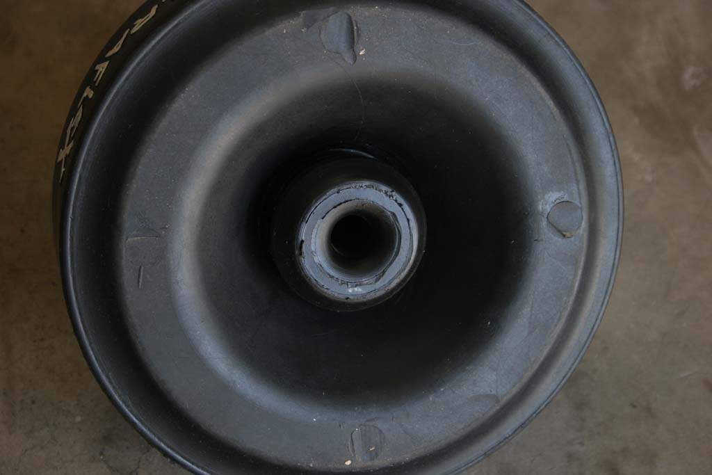
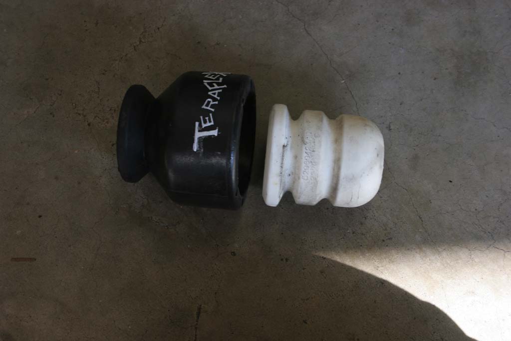
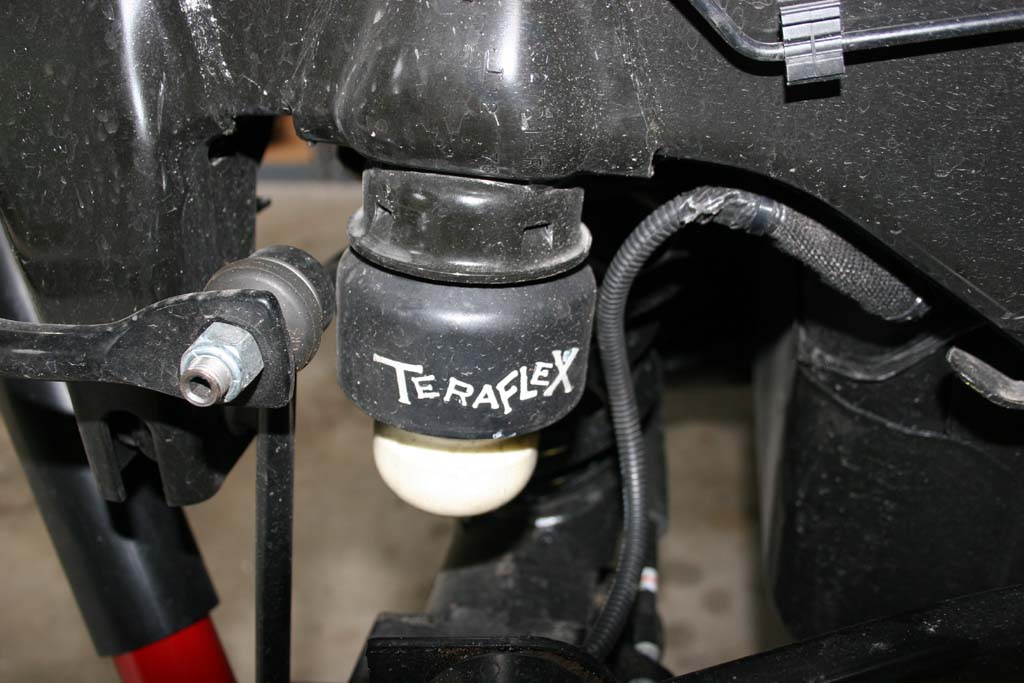
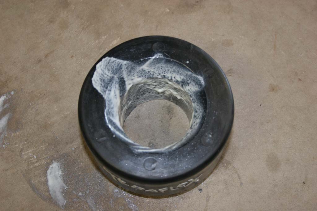
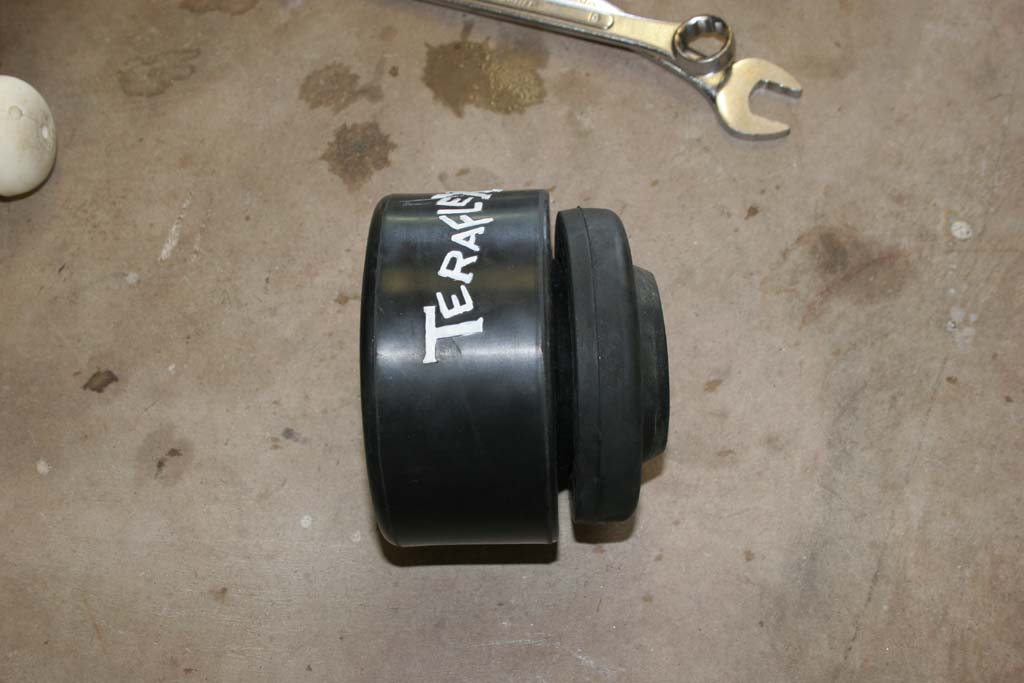
| 12. Push the bumpstop into the bumpstop extensions. You can do this after you install the bump stop extension in the bump stop cup. |
 |
 |
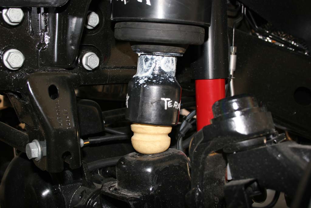
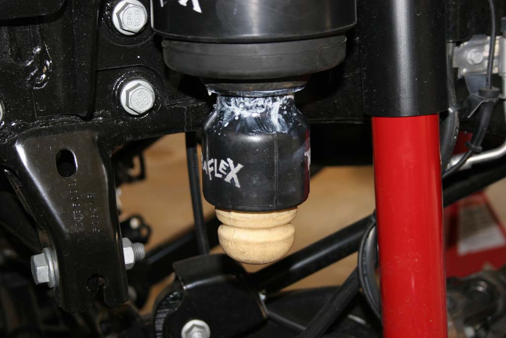
| 13. Installing the front bump stop extensions is not as easy as installing the rears. I used the front spring pad to press these up into the spring cup. You can also place a piece of 2x4 between the Teraflex bumpstop extension and the axle spring pad. |
 |
 |
| |
|
|
| |
|
| |
|
| |
|
|
| |
|
| |
|
|
| 17. Install the rear anti-swaybar links as the new front anti-swaybar links with a 18mm socket and combo wrench for the lower bolt and a 18mm socket and 19mm combo wrench for the upper stud. |
|
|
| 18. Reinstall the tires and check for clearance between the rims and any bolts. Lower the Jeep to the ground and tighten the upper control arm bolts, lower control arm bolts, and track bar bolts. |
| |
| Check all torques after 300 miles. |
| |
N-m |
Ft.
Lbs. |
In.
Lbs. |
| Front: |
Shock Absorber Upper Nut |
27 |
20 |
— |
Shock Absorber Lower Nut |
76 |
56 |
— |
Suspension Arm Lower Axle Bracket Nut |
169 |
125 |
— |
Suspension Arm Lower Frame Bracket Nut |
169 |
125 |
— |
Suspension Arm Upper Axle Bracket Nut/Bolt |
102 |
75 |
— |
Suspension Arm Upper Frame Bracket Bolt |
102 |
75 |
— |
Stabilizer Bar Link Upper Nut |
102 |
75 |
— |
Stabilizer Bar Link Lower Bolt |
102 |
75 |
— |
Track Bar Frame Bracket Nut |
169 |
125 |
— |
Track Bar Axle Bracket Bolt |
169 |
125 |
— |
| Rear: |
Shock Absorber Upper Bolts |
50 |
37 |
— |
Shock Absorber Lower Nut |
76 |
56 |
— |
Suspension Arm Lower Axle Bracket Nut |
169 |
125 |
— |
Suspension Arm Lower Frame Bracket Bolt |
169 |
125 |
— |
Suspension Arm Upper Axle Bracket Bolt |
169 |
125 |
— |
Suspension Arm Upper Frame Bracket Bolt |
169 |
125 |
— |
Stabilizer Bar Link Nut/Bolt |
102 |
75 |
— |
Stabilizer Bar to Link Nut |
90 |
66 |
— |
Track Bar Frame Bracket Nut |
169 |
125 |
— |
Track Bar Axle Bracket Bolt |
169 |
125 |
— |


